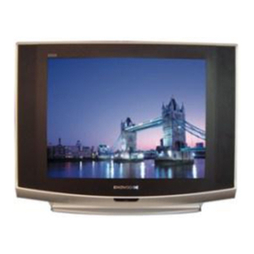
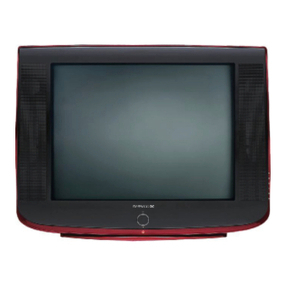
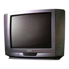
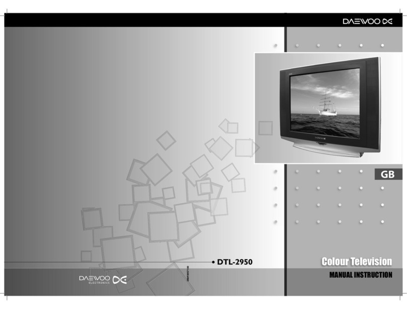
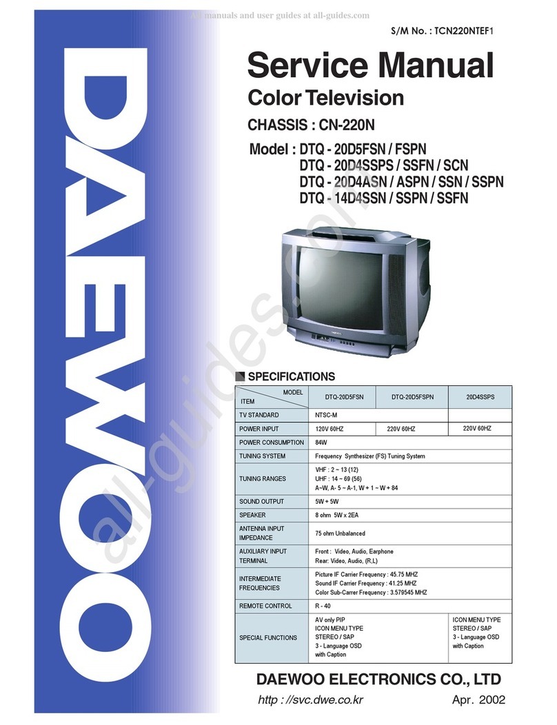
Daewoo DTJ-28G8F User manual

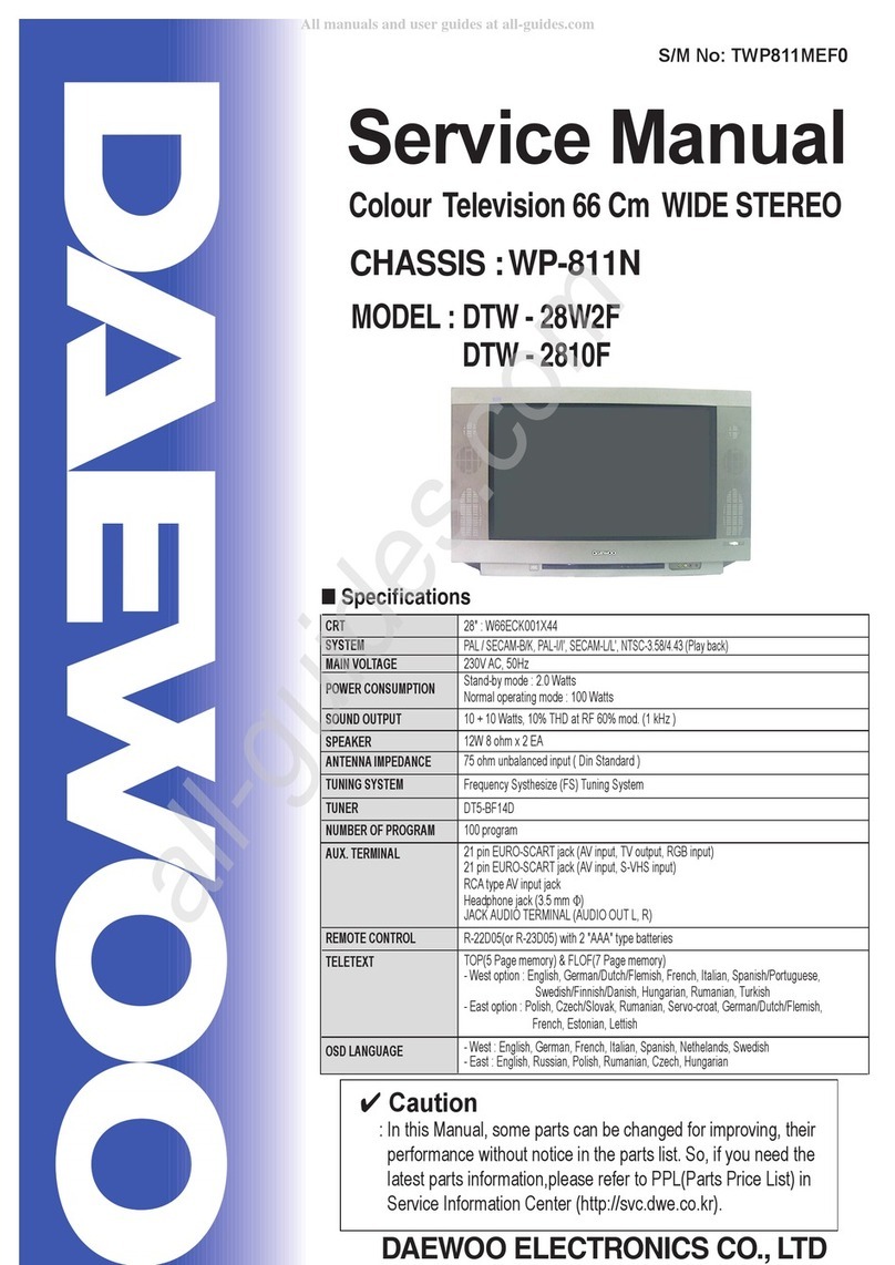
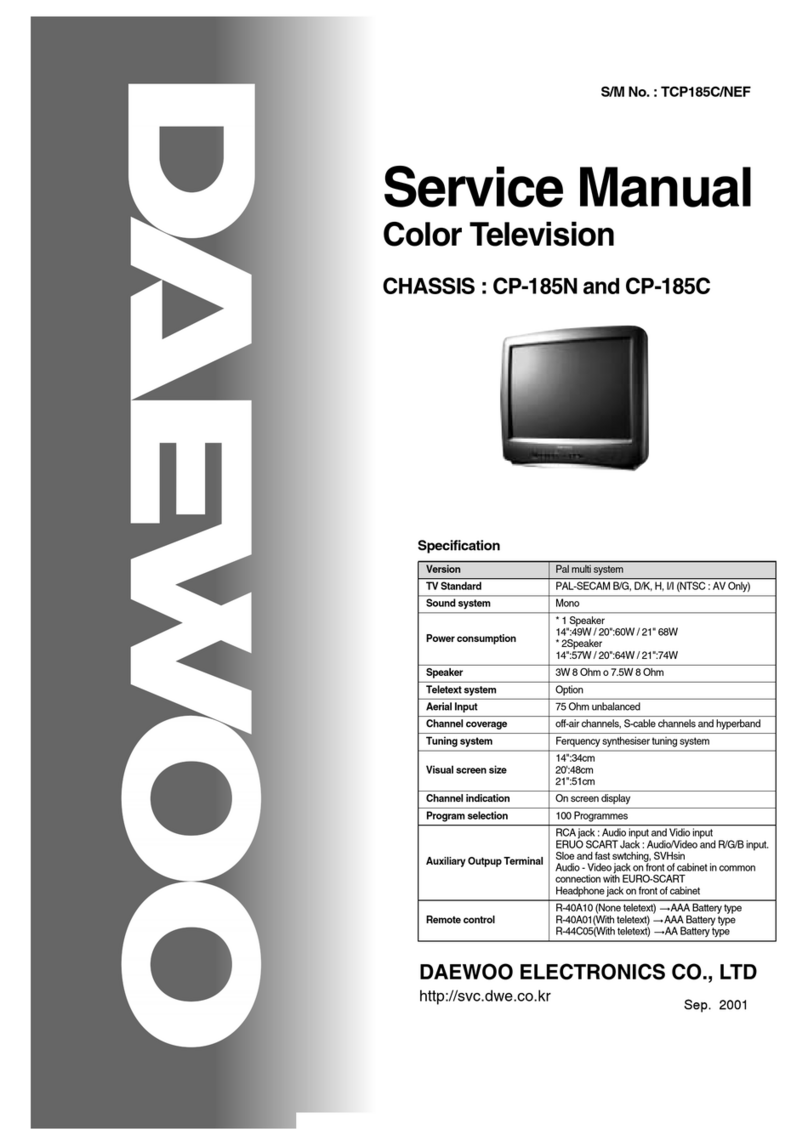
Service Manual
66 Cm STEREO Colour Television
CHASSIS : CP-810
DAEWOO ELECTRONICS CO., LTD.
http://svc.dwe.co.kr MAR,2000
MODEL : DTJ - 28A6F
DTJ - 28A7F
DTJ - 28B1F
DTJ - 28G6F
DTJ - 28G7F
DTJ - 28G8F
S/M No: CP810P-010

1
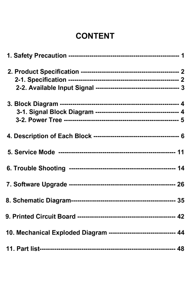
TABLE OF CONTENTS
1. Safety Instruction ........................................................................................................................ 2
2. Specifications .............................................................................................................................. 3
3. Circuit block Diagram ................................................................................................................. 5
4. Alignment Instructions ............................................................................................................... 6
5. IC Description .............................................................................................................................. 12
6. IC DC Voltage Charts ..................................................................................................................32
7. Service Parts List/Recommendable Spare Parts List .............................................................. 35
8. Mechanical Exploded View......................................................................................................... 45
9. Printed Circuit Board ..................................................................................................................51
10. Schematic Diagram ..................................................................................................................... 52

2
1. Safety Instruction
WARNING
:Onlycompetentservicepersonnelmaycarryoutworkinvolvingthetestingorrepairofthisequipment
1.Excessivehighvoltagecanprodecepotentiallyhaz-
ardousX-RAYRADIATION.Toavoidsuchhazards,
thehigh voltage must not exceed the specified limit.
Thenominalvalueofthehighvoltageofthisreceiveris
23-24kvatmax beam current.Thehigh voltagemust
not,underanycircumstances,exceed 30kv.
Eachtimeareceiverrequire servicing,thehigh volt-
ageshouldbechecked.Itisimprortanttouseanaccu-
rateandreliablehighvoltagemeter.
2.TheonlysourceofX-RAYRadiationinthisTVreceiver
isthepicturetube.ForcontinuedX-RAY RADIATION
protection, the replacement tube must be exactly the
sametype tube as specified in the partslist.
X-RAY RADIATION PRECAUTION
1.Potentialsofhighvoltagearepresentwhenthis
receiverisoperating.Operationofthereceiveroutside
thecabinetor withthe backboard removedinvolvesa
shockhazardfromthereceiver.
1)Servicingshouldnotbeattemptedbyanyonewhois
notthoroughlyfamiliarwiththeprecautionsneces-
sarywhenworkingonhigh-voltage equipment.
2)Dischangethehigh potentialof thepicture tube
beforehandlingthetube.Thepicturetubeishighly
evacuated andifbroken, glassfragmentswill be
violently expelled.
2.IfanyFuseinthisTVreceiverisblown,replaceitwith
theFUSEspecifiedin theReplacementParts List.
3.Whenreplacingahighwattage resistor(oxidemetal
filmresistor)in circuitboard,keepthe resistor10mm
awayfrom circuit board.
4.Keepwiresawayfromhighvoltageorhightempera-
turecomponents.
5.ThisreceivermustoperateunderAC230volts,50Hz.
NEVERconnect to DC supply or any other power or
frequency.
SAFETYPRECAUTION
Manyelectricaland mechanicalparts inthis have
specialsafety-related characteristics. Thesecharac-
teristicsareoftenpassedunnoticedbyavisual
inspectionandtheX-RAYRADIATIONprotection
affordedbythemcannotnecessarilybeobtainedby
usingreplacement components rated for higher volt-
age,wattage, etc.Replacement parts whichhave
thesespecial safety characteristics are identifiedin
thismanual and itssupplements, electricalcompo-
nentshavingsuchfeaturesareidentifieddesignated
symbolon the partslist.
Beforereplacinganyofthesecomponents,readthe
partslistinthis manualcarefully.Theuse ofsubstitute
replacementparts whichdo nothave thesame safety
characterisiticsasspecifideinthepartslistmaycreate
X-RAYRadiation.
PRODUCTSAFETYNOTICE
3
2. Specifications
CRT 28" : A66EAK071X54 ( PHILIPS )
System PAL/SECAM-B/G, D/K, PAL-I/I’, SECAM-L/L’, NTSC-3.58/4.43 (Play back )
Main Voltage 230V AC, 50Hz
Power Consumption Stand-by mode : 2.0 Watts
Normal operating mode : 80 Watts
Sound output 10 + 10 Watts, 10% THD at RF 60% mod. ( 1 kHz )
Speaker 12W 8ohm x 2 EA
Antenna Impedance 75 ohm unbalanced input (Din Standard )
Tuning system Frequency Synthesize(FS) Tuning System
Tuner DT5-BF14D, EL2782-105-B
Number of Program 100 programs
Aux. Terminal 21 pin EURO-SCART jack ( AV input, TV output, RGB input )
21 pin EURO-SCART jack ( AV input, S-VHS input )
RCA type AV input jack
Headphone jack ( 3.5 mm )
JACK AUDIO TERMINAL (AUDIO OUT L, R)
Remote controller R-22D05 with 2 "AAA" type batteries
Teletext TOP(5 Page memory) & FLOF(7 Page memory)
- West option : English, German/Dutch/Flemish, French, Italian, Spanish/Portuguese,
Swedish/Finnish/Danish, Hungarian, Rumanian, Turkish
- East option : Polish, Czech/Slovak, Rumanian, Servo-croat, German/Dutch/Flemish,
French, Estonian, Lettish
OSD language - West : English, German, French, Italian, Spanish, Nethelands, Swedish
- East : English, Russian, Polish, Rumanian, Czech, Hungarian
O
l

4
PIN Signal Designation Matching Value
1Audio Out (linked with 3) 0.5Vrms, Imp < 1 k (RF 60% MOD)
2Audio In (linked with 6) 0.5Vrms, Imp < 10 k
3Audio Out (linked with 1) 0.5Vrms, Imp < 1 k (RF 60% MOD)
4Audio Earth
5Blue Earth
6Audio in (linked with 2) 0.5Vrms, Imp < 10 k (RF 60% MOD)
7Blue in 0.7Vpp 2dB, Imp 75
8Slow (Function) Switching TV : 0-2V, PERI : 9.5 - 12V, Imp > 10 k
9Green Earth
10 NC
11 Green In 0.7Vpp 2dB, Imp 75
12 NC
13 Red Earth
14 Rapid(Blanking) Switching Earth
15 Red In, C In 0.7Vpp 2dB, Imp 75
16 Rapid(Blanking) switching Logic 0 : 0 - 0.4V, Logic 1 : 1 - 3V, Imp 75
17 Video Earth
18 Rapid Blanking Earth
19 Video Out 1Vpp 2dB, Imp 75
20 Video In, Y In 1Vpp 2dB, Imp 75
21 Common Earth
Specifications
+
-
+
-
+
-
+
-
+
-

5
3. Circuit Block Diagram

6
4. Alignment Instructions
4-1.UserRemocon
R-22D05

7
R-23D05
Alignment Instructions

8
Alignment Instructions
*HowtoEnterthe“ServiceMode”withuserremocon.
1)SettheTVPr 91
2)Sharpness“MIN“control.
3)Red,Green,Yellowbuttons inregularsequencywithin 5secondsaftersettingTV poweroff.
4)YoucanseetheMenuof“servicemode“onthescreen.
5)The PRUP/DOWNbuttonsontheremotecontrollerareusedtomovetheselectionbarupordowntheMenus.
6)TheVOLUP/DOWNbuttonsontheremotecontrollerareusedtoadjustlevels.
7)Ifyouwanttoexitfrom“ServiceMode“thenpowertheTVoff.
-Youcansee theSVCMenu byOSDinTV set.
V. Slope
V.Center
V.Size
S.Curve
H.Center
H.Width
EW.Para
EW.CorT
EW.CB
EW.Sym
R.bias
G. b
B.b
R.drive
G. d
B.d
G2
SubBri
DT
005
995
220
019
-190
510
382
028
500
021
370
311
311
330
315
330
330
021
048
SVC v1

9
4-2.AFT
Standard B/G, D/K,Iand L
1)SetaSignalGeneratorwith
-RFFREQUENCY=38.9MHz,
-RFOUTPUTLEVEL=80 5dBuV
-Pattern =ColorBar
-System=PAL-B/G
2) ConnecttheSignalGeneratorRFOutput toTP2(TunerIFOutput).
Theremustbenosignal inputtothetuner.
3)SettheL109toTP1(I101,#22)withDCVoltageto2.5V 0.1V
4-3.AGC
1)SetaPatternGeneratorwithRFLEVEL60 3dBuV,RFFrequency210.25MHz(10CH),PatternColorBar.
2)ConnectaOSCILLOSCOPEPROBEtoP101(TUNERAGCINPUT).
3) SettheRBOItoP101(TunerAGCInput) withDCVoltageto2.8V 0.2V
4-4.SCREEN(G2)
1) SetaPatternGeneratorwith-RF Frequency:210.25MHz(10CH)
-Pattern:RETMA
2)Selectthe“G2”inMenu
3) AndaHorizontalLinewillappear onthescreen.
4)AdjusttheSCREENVOLUME onFBTbarelytoseetheHorizontalLine.
5)PressthePRUP/DOWNkeystofinishtheSCREENadjustment.
4-5.FOCUS
1)ApplyaRETMAPATTERNsignal.
2)AdjusttheFOCUSVOLUMEonFBTtoobtain optimalresolution.
4-6.GEOMETRY
4-6-1 VERTICAL SLOPE ( Fixed : Adjust if need be )
1)ApplyaRETMAPATTERNSignal.
2)SettheTVtoNormalI mode.
3)Adjustthehighersemicircleandthelowersemicircletobethesame,withtheV.Slopebyvolume
Up/Downkeys.
4-6-2 VERTICAL CENTER
1)ApplyaRETMAPATTERNSignal.
2)SettheTVtoNormalI mode.
3)Adjustthecenterof the picturewiththeV.Centerby volumeUp/Downkeys.
Alignment Instructions
+
-
+
-
+
-
+
-

10
4-6-3 VERTICAL SIZE
*TheVERTICALCENTERadjustmenthastobedoneinadvance.
1)ApplyaRETMAPATTERNSignal.
2)SettheTVtoNormalI mode.
3)AdjusttheVERTICAL SIZEofthepicture withtheselectV.size by
volumeUP/DOWNkeys.
4-6-4 VERTICAL S-CORRECTION ( Fixed : Adjust if need be )
1)ApplyaCROSSHATCHPATTERNSignal.
2)Adjustthe S-CORRECTION toobtainthe samedistancebetween
horizontallines withtheS.Curve byvolumeUP/DOWN keys.
4-6-5 HORIZONTAL CENTER
1)ApplyaRETMAPATTERNSignal.
2)AdjustpicturecenteringwiththeselectH.CenterbyvolumeUP/DOWNkeys.
4-7. EW
4-7-1 WIDTH
1)ApplyaRETMAPATTERNSignal.
2)Adjustthehorizontalwidthto make aperfectcirclewiththe selectH.Width
byvolumeUP/DOWNkeys.
4-7-2 PARA
1)ApplyaCROSSHATCHPATTERNSignal.
2)Adjust theverticallineto straightwiththeselect E.WParabyvolume
UP/DOWNkeys.
4-7-3 CORNER ( Fixed : Adjust if need be )
1)ApplyaCROSSHATCHPATTERNSignal.
2)Adjusttheverticallinetostraightwiththeselect EW.CorTbyvolume
UP/DOWNkeys.
4-7-4 SYMMETRY ( Fixed : Adjust if need be )
1)ApplyaCROSSHATCHPATTERNSignal.
2) Adjustthesymmetricalbalancetobe suitablewiththeselectEWSym by
volumeUP/DOWNkeys.
Alignment Instructions

11
4-8. WHITE BALANCE
4-8-1 RGB Reference R
4-8-2 Beam Reference LOW ( 288, 301 : 10Cd/ )
HIGH ( 288, 301 : 10Cd/ )
4-8-3 Adjust G, B Gain with select Menu G,B of BIAS, DRIVE of select Menu so that R, G, B Bars
are on the center position of the analog meter. If R Analog meter is not on center, control
the Brightness +/- of user Remocon so as R Analog meter to be on the center position.
4-9. SUB BRIGHT
4-9-1 Pattern : Retma
4-9-2 Adjust the SUB BRIGHT with the select Sub Bri by volume UP/DOWN keys.
so that only H-Center parts of picture can be seen.
4-10. DOUBLE TEXT CENTER
4-10-1 Pattern : Pattern RED
4-10-2 Select Menu
4-10-3 Select DT in SVC menu time to see the Double Text Picture.
( Left : RF Picture, Right : Text Picture )
4-10-4 Change the Double Text control keys volume UP/DOWN keys so that the left edge of text
picture concur with the right edge of RF picture.
Alignment Instructions
m2
m2

12
5. IC description
5-1.ST92195
(1) General Description
1.1INTRODUCTION
TheST92195 microcnontoller is developed andmanufac-
turedbySTMicroelecrtonicsusingaproprietaryn-well
HCMOSprocess.Itsperformancederivesfromtheuseof
aflexible256-registerprogrammingmodelforultra-fast
contextswitchingandreal-timeeventresponse.Theintel-
ligentonchipperipheralsoffloadtheST9corefromI/O
anddata managementprocessing tasks allowingcritical
applicationtaskstogetthemaximumuseoffcore
resources.TheST92195MCUsupportslowpowercon-
sumptionandlowvoltage operationforpower-efficient
andlow-cost embedded systems.
1.1.1ST9+Core
TheadvancedCoreconsistsoftheCentralProcessing
Unit(CPU),theRegisterFile and theInterruptcontroller.
Thegeneral-purposeregisterscan beusedas accumula-
tor,Indexregister,oraddresspointers.Adjacentregister
pairsmake up16-bit registers for addressing or16-bit
processing.AlthoughtheST9hasan8-bitALU,thechip
handles16-bitoperations,includingarithmetic,loads/
stores,and memory/register and memory/memory
exchanges.Twobasicmemoryspacesareavailable:
ProgramMemoryandtheRegisterFile,Whichincludes
thecontrolandstatusregisters of theon-chipperipherals.
1.1.2 Power Saving Modes
Tooptimize performance versus power consumption, a
rangeofoperatingmodescanbedynamicallyselected.
Run Mode.
Thisisthefullspeedexecutionmodewith
CPUandperipheralsrunningatthe maximum clock
speeddeliveredby the phaseLockedLoop(PLL) ofthe
ClockControl Unit(CCU).
Wait For Interrupt Mode.
TheWait For Inter-
rupt(WFI)instruction suspends program execution until
aninterruptrequestisacknowledged.During WFI,the
CPUclockishaltedwhiletheperipheralandinterrupt
controllerkeeprunning ata frequencyprogrammable via
theCCU. In this mode, thepower consumption ofthe
devicecanbe reducedby morethan95%(LP WFI).
Wait For Interrupt Mode.
TheWait For Inter-
rupt(WFI)instruction,andiftheWatchdogisnotenable,
theCPUanditsperipheralsstopoperationandtheI/O
portsenterhighimpedancemode.Aresetisnecessaryto
exitfromHaltmode.
1.1.3I/OPorts
Upto28I/OlinesarededicatedtodigitalInput/Output.
TheselinesaregroupedintouptofiveI/OPortsandcan
beconfigureedona bit basisundersoftwarecontrol topro-
videtiming,statussignals,timerandoutput,analoginputs,
externalinterruptsandserialorparallelI/O.
1.1.4TVPeripherals
Asetofon-chipperipheralsformacompletesystemforTV
setand VCR applications:
-VoltageSynthesis
- VPS/WSS Slicer
-TeletextSlicer
-TeletextDisplayRAM
- OSD
1.1.5OnScreenDisplay
ThehumaninterfaceisprovidedbytheOnScreenDisplay
module,thiscanproduceupto26linesofupto80charac-
tersfromaROMdefined 512characterset.The character
resolutionis 10x10 dot.Four charactersizes aresup-
ported.Serialattributesallowtheusertoselectforeground
andbackground. Parallelattributes canbe used toselect
additionalforegroundandbackgroundcolorsandunderline
onacharacterby character basis.
1.1.6TeletextandDisplayRAM
Theinternal8kTeletextandDisplaystorageRAMcanbe
usedtostoreTeletextpagesaswellasDisplayparame-
ters.
1.1.7 Teletext, VPS and WSS Data Slicers
Thethreeon-boarddataslicersusingasingleexternal
crystalareusedtoextract theTeletext,VPSandWSS
informationfromthevideo signal.HardwareHamming
decodingisprovided.
1.1.8 Voltage Synthesis Tuning Control
14-bitVoltageSynthesisusingthePWM (Pulse Width
Modulation)/BRM(BitRateModulation) techniquecanbe
usedtogenetate tuningvoltagesfor TVsetapplications.
Thetuningvoltageisoutputononeoftwoseparateoutput
pins.

13
IC description
1.1.9 PWM Output
Controlof TV settingsis able tobe made with up to eight
8-bitPWMoutputs,withafrequencymaximumof
23,437Hzat8-bitresolution(INTCLK=12MHz).Lowreso-
lutionswithhigherfrequencyoperationcanbepro-
grammed.
1.1.10 Serial Peripheral Interface (SPI)
TheSPIbusisusedtocommunicatewithexternal
devicesviatheSPI,or buscommunication stan-
dards.TheSPIusesoneortwolinesforserialdataanda
synchronousclock signal.
1.1.11StandardTimer(STIM)
TheStandardTimerincludes aprogrammable16-bit
downcounterandanassociated8-bitprescalerwithSin-
gleandContinuouscountingmodes.
1.1.12 Analog/Digital Converter (ADC)
Inadditionthereis a 3channelAnalogto DigitalCon-
verterwithintegralsampleandhold,fast5.7usconver-
siontimerand6-bitguaranteedresolution.
I C
2
RegisterFilebased8/16bitCoreArchitecturewith
RUN,WFI,SLOWandHALTmodes
to operatingtemperaturerange
Upto24MHzOperation@5V 10%
Minimuminstructioncycletime:375nsat16MHzinter-
nal clock
64KBytesROM
256BytesRAMofRegisterfile(accumulator orindex
registers)
256Bytes of on-chipstatic RAM
8KBytesofTDSRAM(TeletextandDisplayRAM)
56-leadShrinkDIPpackage
28fullyprogrammableI/Opins
SerialPeripheral Interface
FlexibleClockcontrollerforOSD,DataSlicerandCore
clocksrunningfromonesinglelow frequencyexternal
crystal.
EnhancedDisplayController with26 rowsof 40/80
characters
- Serial and Parallel attributes
-10x10dotMatrix,512ROMcharacters,definableby
user
-4/3and 16/9supported
(2) Feature
0 C
O
70 C
O
+_
-Rounding,fringe, double width,doubleheight,
scrolling,cursor,fullbackgroundcolour,
semitransparent mode andreducedintensitycolour
supported
Teletextunit,includingDataslicer,AcquisitionUnitand
upto8KBytesRAMforDataStorage
VPSand Wode Screen Signalling slicer
IntegratedSyncExtractorandSyncController
14-bitVoltage Synthesis fortuning referencevoltage
Upto 6 externalinterrupts plus1 non-maskableinter-
rupt
8x8-bitprogrammablePWMoutputswith5Vopen-
drainorpush-pullcapability
16-bitWatchdog timer with8-bit prescale
16-bitstandardtimerwith8-bitprescalerusableasa
Watchdogtimer
3-channelAnalog-to-Digitalconverter; 6-bitguaran-
teed
Richinstruction set and14-Addressing modes
VersatileDevelopment Tools, including Assembler,
Linker,C-compiler,Archiver,SourceLevelDebugger
andHardwareEmulators withReal-Time Operating
System available from third parties
Piggybackboardavailableforprototyping

14
(3) Block Diagram
IC description

15
(4) PIN DESCRIPTION
Figure 2. Pin Description
IC description
RESETReset(input,activelow).TheST9+isinitialised
by the Reset signal. With the deactivation of RESET,
program execution begins from the Program memory
locationpointedtobythevectorcontainedinprogram
memorylocations 00hand 01h.
R/G/BRed/Green/Blue.Video color analog DAC out-
puts
FBFastBlanking.VideoanalogDACoutput.
VODMainpowersupplyvoltage(5V10%,digital)
WSCF, WSCRAnalogpinsfor theVPS/WPPslicerline
PLL.
MCFMAnalog pin for the display pixel frequency multi-
plier.
OSCIN, OSCOUT Oscillator(input and output).
Thesepins connect aparallel-resonant crystal(24MHz
maximum), or an external source to the on-chip clock
oscillatorand buffer. OSCINis theinput of theoscilltor
inverterandinternal clock generator;OSCOUTis the
outputof theoscillator inverter.
VSYNCVertical Sync. Verticalvideo synchronisation
inputtoOSD. Positiveornegative polarity.
HYNC/CSYNC Horizontal/Composite sync. Horizontal
orcompositevideo synchronisationinputtoOSD. Posi-
tive or negativety.
PXFMAnalogpin forthe Display PixelFrequency Multi-
plier
AVDDAnalogVDDofPLL.This pin mustbetied to
VDD externally to the ST92195.
GND Digital circuit ground.
AGND Analog circuit ground(must be tied externally to
digitalGND).
CVBS1 Compositevideoinput signalfortheTeletext
slicerand sync extraction.
CVBS2CompositevideoinputsignalfortheVPS/WSS
slicer. Pin AC coupled.
AVDD1,AVDD2 Analog power supplies(must be tied
externally to AVDD).
TXCFAnalogpin for theVPS/WSS line PLL.
CVBSO, JTDO, JTCK Testpins:leavefloating.
JTMS, TEST0 Testpins :must be tiedto AVDD2.
JTRST0Testpin: mustbetiedto GND.

16
5-2. VPS 3215C(Video Processor)
(3) Block Diagram
(4) Pin Descriptions
IC description
(1) Description
TheVPC3215Cisahigh-quality, single-chipvideofront-
end,whichistargetedfor4:3and16:9,100/120HzTV
sets.
ItcanbeconbinedwithothermembersoftheDIGIT3000
ICfamily(suchasCIP3250A,DDP3300A,TPU3040)
and/oritcanbe usedwith3rd-party products.
(2) Features
-all-digital video processing
-high-performanceadaptive4HcombfilterY/Cseparator
withadjustableverticalpeaking
-multi-standard color decoder PAL/NTSC/SECAM
includingall substandards
-4composite, 1S-VHS input,1 compositeoutput
-integratedhigh-qualityA/Dconvertersandassociated
clampandAGCcircuits
-multi-standard sync processing
-linearhorizontalscaling(0.25...4),aswellasnon-linear
horizontalscaling‘panoramavision’
-PAL +preprocessing (VPC 3215)
-submicronCMOStechnology
Pin1-Ground,AnalogFront-EndGND
Pin2-Ground,AnalogFront-EndGND
Pin3-CCU5MHzClockOutputCLK5
Thispinprovides aclockfrequency for theTV microcon-
troller,e.g.aCCU3000controller,Itisalsousedbythe
DDP3300Adisplaycontrollerasastandbyclock.
Pin4-StandbySupplyVoltageV
Instandbymode,onlytheclockoscillatorisactive,GND
shouldbegroundreference.PleaseactivateRESQbefore
powering-upothersuppliesPins6and 5-XTAL1 Crystal
Input
F
F
STDBY
F
Thesepinsareconnectedtoan20.25MHzcrystaloscilla-
torwhich is digitallytuned byintegrated shuntcapaci-
tances.TheCLK20andCLK5clocksignalsarederived
fromthisoscillator.Anexternalclockcanbefedinto
XTAL1.Inthiscase,clockfrequencyadjustmentmustbe
switchedoff.
Pin7 - Ground, AnalogFront-End GND
Pin9-Ground, OutputPadCircuitry GND
Pin10-InterlaceOutput, INTLC
Thispinsuppliestheinterlaceinformation,0indicatesfirst
field, 1 indicates second field.
F
P

17
IC description
2
Pin12-VerticalSyncPulse,VS
Thispinsuppliestheverticalsyncsignal.
Pin13 - Front Sync Pulse, FSY
Thispinsuppliesthefrontsyncinformation.
Pin14-MainSync/HorizontalSyncPulseMSY/HS
Thispinsuppliesthehorizontalsyncpulseinformationin
line-lockedmode.InDIGIT3000mode,thispinisthemain
syncinput.
Pin15-HelperLineOutput,Helper
Thissignal indicateda helperline in PAL + mode.
Pin16- HorizontalClamp Pulse,HC
Thissignalcanbeusedtoclampanexternalvideosignal,
thatissynchronousto theinputsignal.The timingispro-
grammable.
Pin17-ActiveVideoOutput,AVO
Thispin indicates the active video output data. The signal
isclockedwiththe LLC1 clock.
Pin18-DoubleOutputClock,LLC2
Pin19 - Output Clock, LLC1
Thisistheclockreferencefortheluma,chroma,andsta-
tus outputs.
Pin26-Ground,OutputPadCircuitryGND
Pin20to25,28,29 -LumaOutputY0-Y7
Theseoutputpinscarrythedigitalluminancedata.The
dataareclockedwiththeLLC1clock.
Pin30- MainClock OutputCLK20
Thisisthe20.25MHzmainclockoutput.
Pin31-SupplyVoltage,DigitalCircuitryV
Pin34-Ground,DigitalCircuitryGND
Pin35-Ground,OutputPadCircuitryGND
Pin36- SupplyVoltage, OutputPad SupplyV
Pin38to43,46,47 -ChromaOutputsC0-C7
TheseoutputscarrythedigitalCrCbchrominancedata.
ThedataareclockedwiththeLL1clock.Thedataare
sampledathalftheclockrateandmultiplexed.TheCrCb
multiplexisresetforeachTVline.
Pin48to50-PictureBusPriorityPR0-PR2
ThePictureBusPrioritylinescarrythedigitalpriority
selectionsignals.Thepriorityinterfaceallowsdigital
switchingof up to 8 sources to the back-endprocessor.
Switchingfordifferentsourcesisprioritizedandcanbeon
aperpixelbasis.
Pin51-Ground,OutputPadCircuitryGND
Pin52 - VGAV-Input.
Thispinis connectedto thevertical syncsignal ofa VGA
signal.
Pin53-Front-End/Back-EndData FPDAT
ThispininterfacestotheDDP3300Aback-endprocessor.
Theinformationforthedeflectiondrivesandforthewhite
drivecontrol,i.e.thebeamcurrentlimiter,istransmittedby
thispin.
Pin 54 - Reset Input RESQ
AlowlevelonthispinresetstheVPC32xx.
Pin55- BusData SDA
Thepinconnectstothe busdataline.
Pin57-TestInputTEST
Thispinenablesfactorytestmodes.Fornormaloperation,
itmust be connectedto ground.
Pin59 - Ground, AnalogFront-End GND
Pins62,61,60,58- Video1-4
Thesearethe analogvideo inputs.ACVBS orS-VHS
lumasignalisconvertedusingtheluma(Video1)ADcon-
verter.TheVIN1inputcanalsobeswitchedtothechroma
(Video2)ADC.TheinputsignalmustbeAC-coupled.
Pin63-ChromaInput CIN
ThispinisconnectedtotheS-VHSchromasignal.Aresis-
tivedivideris usedtobias theinput signal tothe middleof
theconverterinput range.CIN canonly beconnected to
thechroma(Video2)A/Dconverter.Thesignalmustbe
AC-coupled.
Pin64 - Analog VideoOutput, VOUT
Theanalogvideo signalthat isselected forthe main
(luma,CVBS)ADCisoutputatthispin.Anemitterfollower
isrequiredatthispin.
Pin65 -Ground, AnalogShield Front-End GND
Pin66 -Supply Voltage, Analog Front-End V
Pin67- SignalGND forAnalogInput ISGND
Thisisthehighqualitygroundreferenceforthevideo
inputsignals.
Pin68- ReferenceVoltage Top VRT
Viathispin,thereferencevoltagefortheA/Dconvertersis
decoupled.Thepin is connectedwith10uF/47nF tothe
SignalGroundPin.
P
SUPD
D
P
SUPP
P
IC
2
IC
2

18
5-3. CIP3250A (Component Interface Processor)
IC description
(1) Description
TheCIP3250AisanewCMOSICthatcontainsonasin-
glechip the entirecircuitry tointerface analogYUV/RGB/
FastBlanktoadigital YUVsystem.TheFastBlanksignal
isusedtocontrolasoftmixerbetweenthedigitizedRGB
and an external digital YUV source. The CIP supports var-
iousoutputformatssuchasYUV4:1:1/4:2:2orRGB4:4:4.
TogetherwiththeDIGIT3000(e.g.VPC32xxA)orDIGIT
2000(e.g.DTI2250),aninterfacetoaTV-scanratecon-
versioncircuitand/ormulti-mediaframe buffer canbe
obtained.
(2) Feature
-analog inputfor RGBor YUVand FastBlank
-triple8bit analogtodigitalconverters for RGB/YUVwith
internalprogrammableclamping
-single 6bit analogto digital converterfor FastBlank
singnal
-digitalmatrixRGB=>YUV(Y,B-Y,R-Y)
-lumacontrastandbrightness correction forsignalsfrom
analoginput
-colorsaturationandhuecorrectionforsignalsfrom
analoginput
-digitalinputforDIGIT2000orDIGIT3000formats
-digitalinterpolationto4:4:4format
-highquality softmixercontrolled byFastBlank signal
-programmabledelaystomatchdigitalYUVinandanalog
RGB/YUV
-variablelow pass filtersforYUV output
-digitaloutputinDIGIT2000andDIGIT3000formats,as
well as RGB 4:4:4
- businterface
-clockfrequency13.5...20.25MHz
I C
2
(3) Block Diagram

19
IC description
(4) Pin Description
Pin1-STANDBYInput
Viathisinputpin,thestandbymodeoftheCIP3250Ais
enabled.Ahighlevelvoltageswitchesalloutputsto
tristatemode,andpowerconsumptionissignigicantly
reduced.WhentheICISreturnedto activemode,areset
isgeneratedinternally.ConnecttoVSSifnotused.
Pins2to9-B7toB0BlueOutput
Inastand aloneapplication, wherethe CIP3250A serces
asanA/D-converter,thesearetheoutputforthedigital
Bluesignal(purebinary)orthedigitalUsignal(2’s com-
plement).Leavevacantifnotused.
Pin10to17-GL7toGL0Green/LumaOutput
Attheseoutputs,thedigitalluminancesignalisreceivedin
purebinarycided formatfor DIGIT2000 andDIGIT3000
applications.Inastandaloneapplication,wheretheCIP
3250AservesasanA/D-converter,thesearetheoutputs
forthedigitalGreensignal(purebinary)orthedigitalluma
signal(purebinary).Leavevacantifnotused.
Pin18-PVSSOutputPinGround
Thisisthecommongroundconnectionofalloutputstages
andmustbeconnectedtoground.
Note:Allgroundpinsofthechip(i.e.
18,52,58,60,62,64,66and68)mustbeconnectedtogether
lowresistive.Thelayoutof thePCBmusttake intoconsid-
erationtheneed fora low-noiseground.
Pin19-PVDDOutputPinSupply +5V/+3.3V
Thispinsuppliesalloutputstagesandmustbeconnected
toa positive supplyvoltage.
Note:ThelayoutofthePCBmusttakeintoconsideration
theneedforalow-noisesupply.Abypasscapacitorhasto
beconnectedbetweengroundandPVDD
Pins20to27-RC7toRC0Red/ChromaOutput
Thesearetheoutputsforthedigitalchromasignalinthe
DIGIT3000 system,where Uand Vare multiplexed byte-
wise.InaDIGIT2000system,RC3toRC0andRC7to
RC4carrythe halfbyte(nibble)multiplexformat. In astand
aloneapplication,wheretheCIP3250AsercesasanAD-
converter,thesearetheoutputsforthedigitalRedsig-
nal(purebinary) or thedigital chromaV signal(2’scompo-
nent).Leavevacantifnotused.
Pin 29 - AVI Active Video Input
InaDIGIT2000application,thisinputcanbeconnected
toground.InaDIGIT3000application,thisinputexpects
theDIGIT3000 AVIsignal. Ina standalone application,
thisinputexpectstheVSYNCverticalsyncpulse.Connect
groundifnotused.
Pin30- FSYFront SyncInput
InaDIGIT2000application,thisinputpinexpectsthe
DIGIT2000SKEWprotocol.InaDIGIT3000application,
thisinputexpectstheDIGIT3000FSYprotocol.Inastand
aloneapplication,thisunput expectstheHSYNC horizon-
talsyncpulse.Connecttoground ifnotused.
Pin31to32- SDA andSCLof -Bus
Thesepinsconnecttothe bus,whichtakesoverthe
controloftheCIP3250Aviatheinternalregisters.The
SDApinis thedata input/output,and theSCL pinisthe
clockinput/outputof buscontrolinterface.Allregisters
arewriterable(except address hex27)and readable.
Pin33to 35 -PRIO0to PRIO2PriorityBus
ThesepinsconnecttothePriorityBus of aDIGIT3000
application.ThePictureBusPrioritylinescarrythedigital
priorityselectionsignals.Thepriorityinterfaceallowsdigi-
talswitchingofupto8sourcestothebackendprocessor.
Switchingfordifferentsourcesisprioritizedandcanbeon
aperpixelbasis.Inallotherapplications,theymustnotbe
connected.
Pin36 to43 -C0 toC7 ChromaInput
Theseare the inputsfor the digitalchroma signal which
canbereceivedinbinaryoffsetor2’scomplementcoded
format.Ina DIGIT2000(4:1:1)system, C3toC0 takethe
halfbyte(nibble)multiplexformat.C7toC4havetobe
connectedtoground.WithintheDIGIT3000(4:2:2)sys-
tem,UandVaremultiplexedbytewise.Connecttoground
ifnotused.
IC
2
I C
2
I C
2
Table of contents
Other Daewoo TV manuals

Daewoo
Daewoo DTT-3250MT User manual

Daewoo
Daewoo DTQ-29M2FS User manual

Daewoo
Daewoo DTL-2950 User manual

Daewoo
Daewoo DTQ-29U1SC/SSP User manual

Daewoo
Daewoo 15U7LT User manual

Daewoo
Daewoo DTH-2066FS User manual

Daewoo
Daewoo DTC Series User manual

Daewoo
Daewoo DTD-29U9WPT User manual

Daewoo
Daewoo DTM-29U7Z SERIES User manual

Daewoo
Daewoo DTR-29M5MP User manual

Daewoo
Daewoo T011 User manual

Daewoo
Daewoo DTH-29U3 User manual

Daewoo
Daewoo DTH-14V1FS User manual

Daewoo
Daewoo DTH-2930SSFV User manual

Daewoo
Daewoo DTA-14C4TFF User manual

Daewoo
Daewoo DTQ-14N2FC User manual

Daewoo
Daewoo DTQ 13V6FCB User manual

Daewoo
Daewoo DSC-3270E User manual

Daewoo
Daewoo DTW - 28W2F User manual

Daewoo
Daewoo DTD-21H9 User manual