Daikin McQuay RCS 06F User manual

© 2013 Daikin McQuay
Installation Manual IM 962-2
Air-Cooled Split System Condensing Units
Group: Applied Air Systems
Part Number: IM 962-2
Date: August 2013
Models RCS 06F – 20F
6.5 to 20 Tons
R-410A Refrigerant
6.5 – 7.5 Tons
10.0 – 12.0 Tons
15.0 – 20.0 Tons

2 IM 962-2
Table of Contents
Introduction .................................3
Hazard Identication Information ................3
Checking Product Received ....................3
Standard Unit Features .......................4
Dimensional and Weight Data ..................6
Physical Data ................................8
Unit Capacity and Physical Data . . . . . . . . . . . . . . . . 8
Electrical Data ...............................9
Power Wiring . . . . . . . . . . . . . . . . . . . . . . . . . . . . . . . 9
Installation .................................10
Order Parts ...............................10
Standard Items .............................10
Crankcase Heaters .........................10
Corrosive Environment ......................10
Installation General .........................10
Rooftop Installation ..........................11
Slab Installation . . . . . . . . . . . . . . . . . . . . . . . . . . . . 11
Installation of Piping .........................12
Typical Piping Recommendations ..............12
Electrical Wiring ............................14
Refrigerant Charge ..........................16
Evaporator Coil ............................17
Evacuation and Charging .....................17
Final Leak Testing ..........................18
Accessory Installation .......................19
Maintenance and Operation ...................20
Charging Charts ............................21
Wiring Diagrams ............................27
Service and Warranty Procedure ...............29
Replacement Parts .........................29
In-Warranty Return Material Procedure ..........29
Warranty Registration Form ...................30
Quality Assurance Survey Form ................32

IM 962-2 3
Introduction
Introduction
Hazard Identication Information
DANGER
The use of unauthorized components, accessories or devices
may adversely affect the operation of the condensing unit and
may also endanger life and property.
The manufacturer disclaims any responsibility for such loss
or injury and the manufacturer’s warranty does not cover
any damage or defect to the air conditioner caused by the
attachment or use of any components, accessories or devices
(other than those authorized by the manufacturer) into, onto
or in conjunction with the condensing unit.
DANGER
Dangers indicate a hazardous situation which will result in
death or serious injury if not avoided.
WARNING
Warnings indicate potentially hazardous situations, which
canresult in property damage, severe personal injury, or death
ifnot avoided.
CAUTION
Cautions indicate potentially hazardous situations, which can
result in personal injury or equipment damage if not avoided.
This manual contains the installation and operating
instructions for your split condensing unit. There are a
few precautions that should be taken to derive maximum
satisfaction from it. Improper installation can result in
unsatisfactory operation or dangerous conditions.
Read this manual and any instructions packaged with separate
equipment required to make up the system prior to installation.
Give this manual to the owner and explain its provisions. The
owner should retain this manual for future reference.
Checking Product Received
Upon receiving the unit, inspect it for any damage from
shipment. Claims for damage, either shipping or concealed,
should be led immediately with the shipping company.
Check the unit model number, electrical characteristics, and
accessories to determine if they are correct.
Nomenclature
NOTE: For larger size units (greater than 20 ton), refer to Catalog 222.
R C S – 06 – F – 078 – C
Rooftop Condensing System
Nominal capacity (tons)
06 = 6.5
07 = 7.5
10 = 10 (single compressor)
11 = 10 (tandem compressors)
12 = 12
15 = 15
20 = 20
Refrigerant
F = R-410A
Voltage
C = 208/230 - 3 - 60
D = 460 - 3 - 60
Y = 575 - 3 - 60
Compressor
078 = 6.5 ton, single
090 = 7.5 ton, single
120 = 10 ton, single
125 = 10 ton, tandem
150 = 12.5 ton, tandem
180 = 15 ton, tandem
240 = 20 ton, tandem

4 IM 962-2
Introduction
Introduction
Standard Unit Features
Cabinet — Galvanized steel with a durable powder paint
nish. Stamped louvered panels offer 100% protection for the
condenser coil.
Compressor — Hermetically sealed scroll compressors.
Compressors are mounted on rubber-in-shear pads to reduce
vibration and noise.
Condenser Coil — Constructed with copper tubes and
aluminum ns mechanically bonded to the tubes for
maximum heat transfer capabilities. All coil assemblies are
leak tested at 450 psig internal pressure.
Refrigerant Connections — Field piping connections are made
through a xed panel. This allows complete access or removal of
access panels after piping connections have been made.
Crankcase Heater — Standard, all models.
Low Ambient Control — A pressure sensitive fan cycling
control to allow unit operation to 0°F is standard.
Service Valves — Standard on liquid lines and vapor lines.
Service Access — The control box, as well as the
compressor and other refrigerant controls, is accessible
through access panels. It may be opened without affecting
the normal operation of the unit. Condenser fan motors are
accessible by removing wire grilles.
Filter Drier — Field supplied.
Sight Glass — Optional, eld supplied.
Transformer — Step down type, line to 24 volts.
Contactor — The contactor is an electrical switch which
operates the compressor and condenser fans.
High Pressure Control — Opens the contactor circuit on
high refrigerant pressure; manual reset.
Low Pressure Control — Stops compressor operation in the
event of loss of refrigerant.
Condenser Fan Motor (Direct Drive) — Ball bearing 1075
RPM motors are mounted to minimize vibration and noise
problems.These are permanent split capacitor types and
require the same capacitance for both run and start.
Testing — All units are run tested at the factory prior to
shipment. Units are shipped with a holding pressure of nitrogen.
Figure 1: RCS 06F & 07F Ton Features

IM 962-2 5
Introduction
Figure 2: RCS 10F – 20F Ton Features

6 IM 962-2
Dimensional and Weight Data
Figure 3: RCS 06F and 07F Dimensions and Weights Table 1: RCS 06F and 07F Operating Weights
RCS
model
Total
weight
lbs. [kg]
Corner weight lbs. [kg]
A B C D
06F 291 [132] 50 [22.7] 73 [33.1] 69 [31.3] 99 [44.9]
07F 318 [144] 53 [24.0] 84 [38.1] 71 [32.2] 110 [49.9]
Figure 4: RCS 10F and 11F Dimensions and Weights
Table 2: RCS 10F and 11F Operating Weights
RCS
model
Total
weight
lbs. [kg]
Corner weight lbs. [kg]
A B C D
10F
(Single) 501 [228] 123 [53.9] 132 [60.0] 119 [54.1] 127 [58.0]
11F
(Tandem) 586 [266] 144 [65.3] 154 [69.9] 139 [63.2] 149 [67.6]
31.06
43.00
32.81
CONTROL
PANEL ACCESS
SUCTION
LINE 1 LIQUID
LINE
1/2"
1/8"
HIGH VOLTAGE
3/4"DIA. HOLE1
LOW VOLTAGE
7/8"DIA. HOLE
21.69
24.19
26.63
28.44
C
A
D
B
A
B
D
C
CONTROL
PANEL ACCESS
39.94
62.125
44.75
38.375
60.625
7.5
31.25
28.25
16.25
11.25
7.875 8.75
Suction Line
1-3/8" Dia. Hole
Liquid Line
5/8" Dia. Hole
Low Voltage
7/8" Dia. Hole
High Voltage
1-3/4" Dia. Hole

IM 962-2 7
Dimensional and Weight Data
Figure 5: RCS 12F Dimensions and Weights
Table 3: RCS 12F Operating Weights
RCS
model
Total
weight
lbs. [kg]
Corner weight lbs. [kg
A B C D
12F 650 [293] 160 [72.0] 171 [78.0] 154 [70.0] 165 [75.0]
Figure 6: RCS 15F – 20F Dimensions and Weights
Table 4: RCS 15F and 20F Operating Weights
RCS
model
Total
weight
lbs. [kg]
Corner weight lbs. [kg]
A B C D
15F 746 [338.0] 183 [83.0] 196 [89.0] 177 [80.0] 189 [86.0]
20F 952 [432.0] 234 [106.0] 251 [114.0] 226 [103.0] 241 [110.0]
B
A
C
D
CONTROL
PANEL ACCESS
39.94
73.88
72.375
44.75
38.375
7.5
31.25
28.25
16.25
11.25
7.875 8.75
Suction Line
1-3/8" Dia. Hole
Liquid Line
5/8" Dia. Hole
Low Voltage
7/8" Dia. Hole
High Voltage
1-3/4" Dia. Hole
A
D
C
B
CONTROL
PANEL ACCESS
88.88
39.94
87.375
38.375
44.75
7.5
31.25
28.25
16.25
11.25
7.875 8.75
Suction Line
1-3/8" Dia. Hole
Liquid Line
5/8" Dia. Hole
Low Voltage
7/8" Dia. Hole
High Voltage
1-3/4" Dia. Hole
Liquid Line
5/8"
Dia. I.D. 15 Ton
7/8"
Dia. I.D. 20 Ton
Suction Line
1-5/8" Dia. Hole

8 IM 962-2
Physical Data
Physical Data
Unit Capacity and Physical Data
Table 5: RCS 06F – 20F Physical Data
Model RCS
06F Single 07F Single 10F Single 11F Tandem 12F Tandem 15F Tandem 20F Tandem
Capacity and Weight
Capacity (tons) [kW] 6.5 [22.9] 7.5 [26.4] 10 [35.2] 10 [35.2] 12 [42.2] 15 [52.8] 20 [70.3]
Number of circuits 1
Operating weight
(lbs) [Kg] 291 [132] 318 [144] 501 [227.3] 586 [265.8] 650 [294.8] 746 [338.4] 952 [431.8]
Shipping weight
(lbs) [Kg] 314 [142.5] 341 [154.7] 541 [245.4] 626 [284.0] 690 [313.0] 786 [356.5] 992 [450.0]
Compressor
Quantity 1 2
Type Scroll
RPM 3500
Refrigerant charge
R410A oz. [g] 178 [5046] 242 [6861] 339 [9661] 300 [8505] 378 [10,716] 506 [14,345] 655 [18,569]
Condenser Fans
Quantity 123
CFM [L/s] 4700 [2218] 4700 [2218] 8100 [3822] 8100 [3822] 8100 [3882] 12,000 [5663] 12,000 [5663]
Diameter (in.) [mm 24 [610] 24 [610] 24 [610] 24 [610] 24 [610] 24 [610] 24 [610]
Drive Direct
Motor horsepower
each [W] 1/3 [249] 1/3 [249] 1/3 [249] 1/3 [249] 1/3 [249] 1/3 [249] 1/3 [249]
Type PSC
RPM 1075
Condenser Coil
Quantity 1 2
Rows 1-1/2 2 3
Fins per inch 20 22 18 22 22 22 22
Sq. ft. [m2] 23.0 [2.14] 23.0 [2.14] 27.0 [2.51] 27.0 [2.51] 33.9 [3.05] 40.38 [3.75] 40.38 [3.75]
Fins/tubes Aluminum/Copper
Cabinet
Finish Powder Coat
Sheet metal Galvanized
Gauge (nominal) top 20
Sides 20
Base rails 14
Refrigerant Connection
Vapor sweat (in.) [mm] 1-1/8 [29] 1-1/8 [29] 1-3/8 [35] 1-3/8 [35] 1-3/8 [35] 1-5/8 [41.3] 1-5/8 [41.3]
Liquid sweat (in.) [mm] 1/2 [13] 1/2 [13] 5/8 [16] 5/8 [16] 5/8 [16] 5/8 [16] 7/8 [22]

IM 962-2 9
Electrical Data
Electrical Data
Power Wiring
Table 6: RCS 06F – 20F Electrical Data
Model RCS
06F 07F 10F 11F 12F 15F 20F
Compressor Motor
Voltage 208/230 460- 575 208/230 460 575 208/230 460 575 208/230 460 575 208/230 460 575 208/230 460 575 208/230 460 575
Phase and hertz 3 – 60
Number of compressors Single Tandem
Operating Current
Rated load amps (each)122.4 10.6 7.7 25.0 12.2 9.0 30.1 16.7 12.2 17.6 9.6 6.1 22.4 10.6 7.7 25.0 12.2 9.0 33.3 17.9 12.8
Locked rotor amps (each)1149 75 54 164 100 78 225 114 80 123 64 40 14 75 54 164 100 78 239 125 80
Condenser Fan Motors
Voltage 208/230 460 575 208/230 460 575 208/230 460 575 208/230 460 575 208/230 460 575 208/230 460 575 208/230 460 575
Phase Single
Full load amps (each) 2.2 1.3 1.0 2.2 1.3 1.0 2.4 1.4 1.0 2.4 1.4 1.0 2.4 1.4 1.0 2.4 1.4 1.0 2.4 1.1 0.8
System characteristics
Unit full load amps224.6 11.9 8.7 27.2 13.5 10.0 34.9 19.5 14.2 40.0 22.0 14.2 49.6 24.0 17.4 57.2 28.6 21.0 73.8 39.1 28.0
Minimum circuit ampacity 31.0 15.0 11.0 34.0 17.0 13.0 43.0 24.0 18.0 45.0 25.0 16.0 56.0 27.0 20.0 64.0 32.0 24.0 83.0 44.0 32.0
Maximum fuse size (amps)
or HACR circuit breaker
ampacity3
50 25 15 50 25 20 60 40 25 60 30 20 70 35 25 80 40 30 110 60 40
Disconnect size 60 30 30 60 30 30 60 40 25 60 30 30 60 30 30 100 60 60 200 60 60
Note:
1 Each compressor
2 Conditions at 45° suction and 95° ambient
3 Local codes take precedent over recommended fuse size
Figure 7: Control Box Example – RCS 10F Through 20F

10 IM 962-2
Installation
Installation
Order Parts
When reporting shortages or damaged parts, or when
ordering repair parts, give the complete unit model and serial
numbers which are stamped on the unit rating plate.
Standard Items
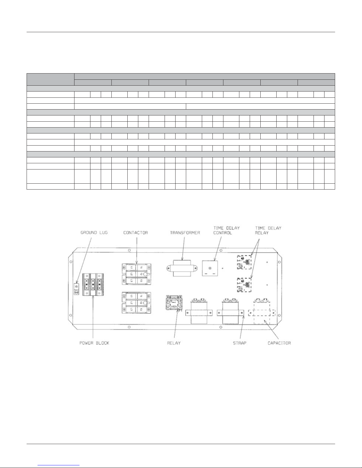
The condensing unit consists of a completely assembled
package which includes a compressor pack, condenser coils,
fans, fan motors, outdoor control box, factory wiring, factory
tubing and ttings.
Crankcase Heaters
These units are equipped with a crankcase heater that is
factory wired to operate whenever the main power supply
to the unit is “ON” and compressors are “OFF.” Before
starting the equipment after prolonged shutdown or at the
time of initial spring startup, be sure that the circuits to the
condensing units are closed for at least 24 hours.
Corrosive Environment
The metal parts of this unit may be subject to rust or
deterioration if exposed to a corrosive environment. This
oxidation could shorten the equipment’s useful life. Corrosive
elements include salt spray, fog or mist in seacoast areas,
sulphur or chlorine from lawn watering systems, and various
chemical contaminants from industries such as paper mills
and petroleum reneries.
If the unit is to be installed in an area where contaminants are
likely to be a problem, special attention should be given to the
equipment location and exposure.
• Avoid having lawn sprinkler heads spray directly on the
unit cabinet
• In coastal areas, locate the unit on the side of the
building away from the waterfront.
• Shielding provided by a protection, based on clearances
DANGER
Disconnect all power to unit before starting maintenance.
Failure to do so can cause electrical shock resulting in severe
personal injury or death.
Regular maintenance will reduce the buildup of contaminants
and help to protect the unit’s nish.
• Frequent washing of the cabinet, fan blade and coil
with fresh water will remove most of the salt or other
contaminants that build up on the unit.
• Regular cleaning and waxing of the cabinet with a good
automobile polish will provide some protection.
• A good liquid cleaner may be used several times a year
to remove matter that will not wash off with water.
Several different types of protective coatings are offered in
some areas. These coatings may provide some benet, but the
effectiveness of such coating materials cannot be veried by
the equipment manufacturer.
Installation General
The condensing unit should be installed outdoors. It should be
located as near as possible to the evaporator section to keep
connecting refrigerant tubing lengths to a minimum. The unit
must be installed to allow a free air ow to the condenser coils
If several units are installed adjacent to each other, take care
to avoid recirculation of air from one condenser to another.
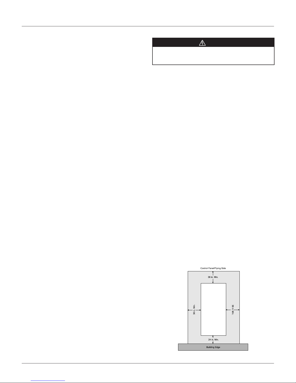
In all installations, adequate space must be provided for
installation and servicing.
The unit must not be connected to any duct work. Do not
locate unit under a roof drip; if necessary, install gutters,
etc., to prevent water runoff onto the unit. To prevent air
recirculation, it is recommended that the unit not be installed
under an overhang. However, if this is necessary, allow a
minimum of 60" above the unit for air discharge
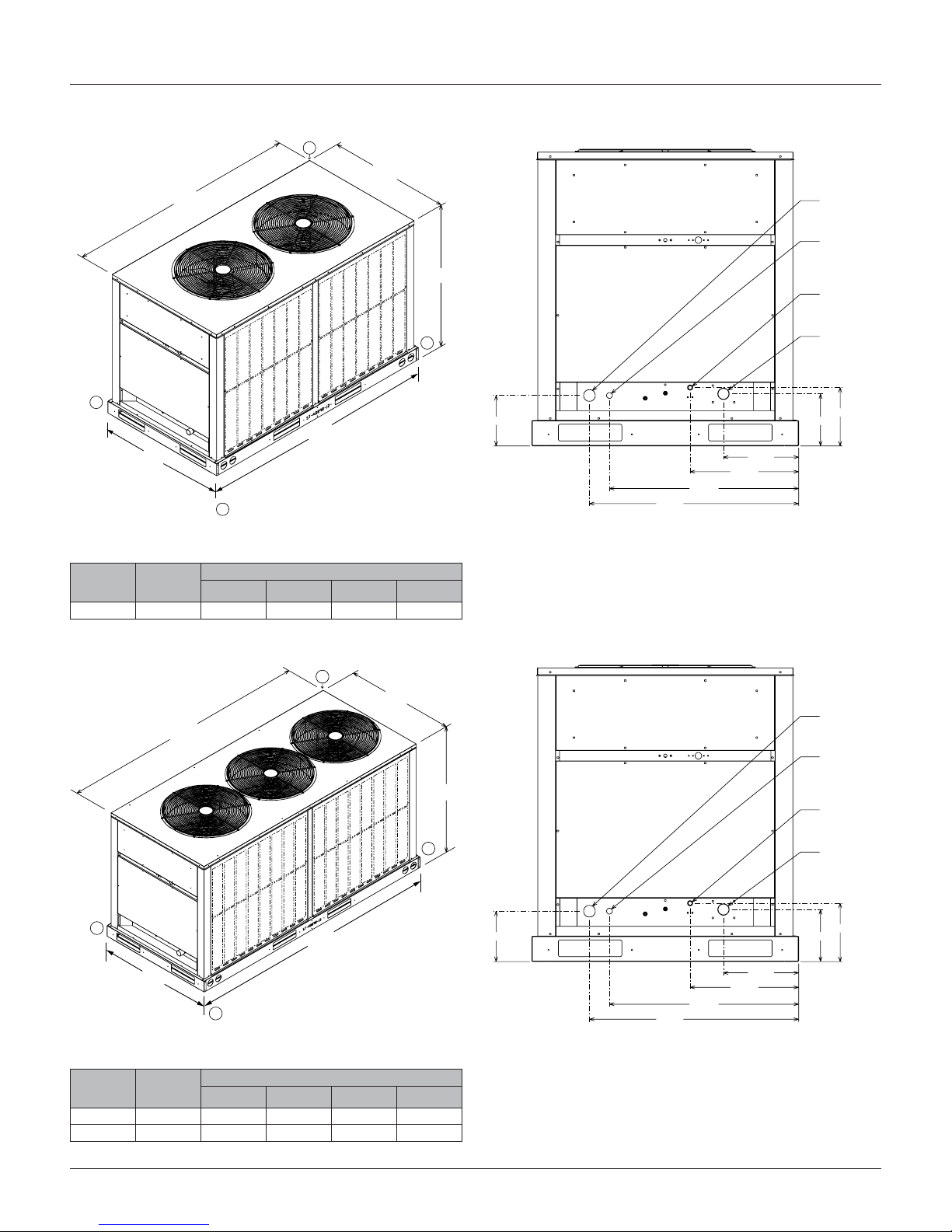
Figure 8: Clearances RCS 06F – 20F Service Clearances

IM 962-2 11
Installation
Installation
Rooftop Installation
If rooftop installation is required, make certain that the
building construction is adequate for the weight of the
unit. (Table 5) Before placing the unit on the roof, make
certain that the nylon rigging slings are of sufcient length
to maintain equilibrium of the unit when lifting. Under no
circumstances should the unit be lifted by only one corner for
rooftop installation.
Slab Installation
Condensing units should be set on a solid level foundation.
When installed at ground level, the unit should be placed on
a 6" cement slab. If the pad is formed at the installation site,
do not pour the pad tight against the structure, otherwise
vibration will be transmitted from the unit through the pad.
Table 7: RCS 06F and 07F Operating Weights
RCS
model
Total
weight
lbs. [kg]
Corner weight lbs. [kg]
A B C D
06F 291 [132] 50 [22.7] 73 [33.1] 69 [31.3] 99 [44.9]
07F 318 [144] 53 [24.0] 84 [38.1] 71 [32.2] 110 [49.9]
10F
(Single) 501 [228] 123 [53.9] 132 [60.0] 119 [54.1] 127 [58.0]
11F
(Tandem) 586 [266] 144 [65.3] 154 [69.9] 139 [63.2] 149 [67.6]
12F 650 [293] 160 [72.0] 171 [78.0] 154 [70.0] 165 [75.0]
15F 746 [338.0] 183 [83.0] 196 [89.0] 177 [80.0] 189 [86.0]
20F 952 [432.0] 234 [106.0] 251 [114.0] 226 [103.0] 241 [110.0]
Figure 9: Rigging

12 IM 962-2
Installation
Installation of Piping
WARNING
Do not use oxygen to purge lines or pressure system for leak
test. Oxygen reacts violently with oil, which can cause an
explosion resulting in severe personal injury or death.
NOTE: The condensing unit is shipped with a holding charge
of dry nitrogen which must be purged from the unit
before evacuation.
Once located, the condensing unit is ready to be
interconnected with the evaporator using ONLY refrigeration
grade dehydrated tubing.The following should be considered
when connecting the tubing.
1. Pitch vapor line toward the compressor approximately
1/2" every 10 feet to facilitate oil return.
2. It is recommended that the sight glass, lter drier and
liquid line solenoid valve be installed in the liquid line
just prior to the evaporator.
3. Silver solder (such as silfos, Easy Flow, etc.) should be
used for all refrigerant joints.
4. Thoroughly clean all joints before uxing. DO NOT
USE ACID FLUX.
5. When uxing, limit the application of paste to the
minimum and always apply ux to the male portion of
the connection.
6. Vapor lines should be insulated to prevent condensate
drip. Use insulation of at least 3/8" wall thickness. The
insulation should be installed on the tubing prior to
making the sweat connections.
7. Insulate the liquid line whenever the heat pickup or
transfer can affect the subcooling.
8. Care should be taken to avoid transmission of noise or
vibration to building structure.
Table 8: Refrigerant Piping Data
Equivalent Length, ft. [m] of Straight Type “L” Tubing
for Nonferrous Valves/Fittings (Brazed)
Tube
Size,
O.D.
Solenoid
Valve
Angle
Valve
Short
Radius
Ell
Long
Radius
Ell
Tee Line
Flow
Tee
Branch
Flow
1/2 70 [21.3] 8.3 [2.5] 1.6 [0.5] 1.0 [0.3] 1.0 [0.3] 3.1 [0.9]
5/8 72 [21.9] 10.4 [3.2] 1.9 [0.6] 1.2 [0.4] 1.2 [0.4] 3.6 [1.1]
3/4 75 [22.9] 12.5 [3.8] 2.1 [0.7] 1.4 [0.4] 1.4 [0.4] 4.2 [1.3]
7/8 78 [23.8] 14.6 [4.4] 2.4 [0.7] 1.6 [0.5] 1.6 [0.5] 4.8 [1.5]
1-1/8 — 18.8 [5.7] 3.0 [0.9] 2.0 [0.6] 2.0 [0.6] 6.0 [1.8]
1-3/8 — 22.9 [7.0] 3.6 [1.1] 2.4 [0.7] 2.4 [0.7] 7.2 [2.2]
1-5/8 — 27.1 [8.3] 4.2 [1.3] 2.8 [0.8] 2.8 [0.8] 8.4 [2.6]
2-1/8 — 35.4 [10.8] 5.3 [1.6] 3.5 [1.1] 10.7 [3.3] 10.7 [3.3]
Typical Piping Recommendations
The following will be of help in accomplishing a successful
1. Size liquid line for no more than 10°F loss which
corresponds to approximately 3 psig pressure drop.
2. Size vapor lines for no more than 2°F loss which
corresponds to approximately 3 psig pressure drop.
3. Install sight glass, lter drier and solenoid valve in
liquid line adjacent to evaporator. Filter drier should be
between the condensing unit and sight glass.
4. Pitch all horizontal vapor lines downward in the
direction of ow (1/2" to 10 ft. run).
5. When making up refrigerant piping, take every
precaution to prevent dirt and moisture from entering
the piping.
6. Locate the condensing unit and evaporator(s) as close
together as possible to minimize piping runs.
7. Liquid or vapor lifts not to exceed 60 ft.
8. To prevent suction line breakage due to vibration and to
prevent tubing noise transmission into the conditioned
space, the suction clamp must be installed after tubing
is brazed as illustrated in Figure 10.
Figure 10: Suction Clamp

IM 962-2 13
Installation
Table 9: Recommended Vapor and Liquid Line Sizes for Various Lengths of Run
Recommended Vapor and Liquid Line Sizes for Various Lengths of Run
Equivalent Length to
Evaporator (ft)
Cooling Model
Liquid Line O.D. Sizes (in) Vapor Line O.D. Sizes (in)
6 7 10 11 12 15 20 6 7 10 11 12 15 20
0 to 15 1/2 1/2 5/8 5/8 5/8 5/8 7/8 1-1/8 1-1/8 1-3/8 1-3/8 1-3/8 1-5/8 1-5/8
16 to 50 1/2 1/2 5/8 5/8 5/8 5/8 7/8 1-1/8 1-1/8 1-3/8 1-3/8 1-5/8 1-5/8 1-5/8
51 to 100 1/2 1/2 5/8 5/8 5/8 3/4 7/8 1-1/8 1-3/8 1-3/8 1-3/8 1-5/8 1-5/8 2-1/8
101 to 150 1/2 1/2 5/8 5/8 5/8 3/4 7/8 1-3/8 1-3/8 1-5/8 1-5/8 2-1/8 2-1/8 2-1/8
NOTE: Line length between condenser and evaporator (suction and liquid) not to exceed 150' equivalent length.
Figure 11: Liquid Line Pressure Drop Per 100 Feet
Equivalent Length (Type L Copper Tubing)
Note:
1. When evaporator coil is above condenser, the pressure
drop due to vertical lift (0.5 PSIG per foot of lift) must
be added to the pressure drop derived from this curve.
2. Size liquid line for no more than 10°F loss
(approximately 30 PSIG total pressure drop).
3. Do not oversize liquid line. Oversized liquid lines add
signicantly to the amount of refrigerant required to
charge the system.
4. The maximum recommended velocity with solenoid
valves or other quick closing devices in the liquid line is
300 FPM.
Figure 12: Suction Line System Capacity Loss In Percent
Per 100 Feet Equivalent Length (Type L Copper Tubing)
Note:
1. The minimum velocity line (700 fpm) is recommended
for cooling only units with vertical or horizontal run
refrigerant lines.
2. For suction pressure drop (PSIG), multiply percent (%)
loss by 1.18.
Figure 13: Typical Drain Piping

14 IM 962-2
Installation
Figure 14: Coil Above Condensing Unit
Figure 15: Coil Below Condensing Unit
Electrical Wiring
NOTE: Field wiring must comply with the National Electric
Code (CEC in Canada) and any local ordinance that
may apply.
Electrical Power
It is important that proper electrical power is available at the
unit. Voltage must not vary more than 10% from that stamped
on the rating plate. (See Table 6 on page 9 for minimum and
maximum voltage.) Interphase voltage variation on three-phase
units must not be more than 3%. Contact local power company
for correction of improper voltage or phase unbalance.
Important: Models equipped with scroll compressors must
be phased correctly for proper compressor rotation. If the
compressor is noisy or if suction and discharge pressures
do not appear normal, reverse any two power leads to the
unit. Extended run time in reverse rotation will damage the
compressor and lead to premature failure.
Power Wiring
Power wiring should be run in grounded rain-tight conduit.
See Table 6 for wire ampacity and proper wire size.
Wire Routing
POWER WIRING MUST BE RUN IN CONDUIT. Conduit
must be run through the connector panel below the service
cover and attached to the bottom of the control box.
If low (extra-low in Canada) voltage control wire is run in
conduit with power supply, Class I insulation is required. If
run separate, Class II is required. Low voltage wiring may be
run through the insulated bushing provided in the 7/8" hole in
the connector panel, then route to the control box.
WARNING
After completing wiring, check all electrical connections, including
factory wiring within the unit. Make sure all connections are tight.
eplace and secure all electrical box covers and access doors before
leaving the unit or turning on power to the unit. Failure to do so can
cause a re or electrical shock resulting in property damage, personal
injury or death.

IM 962-2 15
Installation
Table 10: Field Wire Size for 24 Volt Thermostat
Thermostat Load
Amps Solid Copper Wire –AWG
3.0 16 12 10 10 10
2.5 16 12 12 10 10
2.0 18 14 12 12 10
Length of Run, ft(1) 50 150 200 250 300
(1) Wire length equals twice the run distance.
Grounding
A grounding lug is provided in control box for a ground wire.
Grounding also may be accomplished by grounding the power
line conduit to the unit.
WARNING
This unit must be permanently grounded. A ground lug is
provided near the contactor for a ground wire. Failure to do
so can cause a re or electrical shock resulting in property
damage, severe personal injury or death.
Thermostat
An appropriate thermostat should be mounted on an inside
wall in a location where it will not be affected by the sun
or drafts, from open doors or other sources. Install, level,
and after installation check the thermostat calibration and
recalibrate if necessary. Refer to thermostat manufacturer’s
information for additional installation, checkout and operation
instructions.
Table 11: Copper Wire Size (1% Voltage Drop)
Circuit
Ampacity
Copper Wire Gauge (75°C Insulation)
Distance In Feet
100 150 200 250 300
4064321
45 4 3 2 1 1/0
50 4 3 2 1 1/0
60 4 2 1 1/0 2/0
70 3 2 1/0 2/0 3/0
80 3 1 1/0 2/0 3/0
90 2 1/0 2/0 3/0 4/0
100 2 1/0 2/0 3/0 4/0
110 1 2/0 3/0 4/0 250
125 1 2/0 3/0 4/0 250
Figure 16: Typical Field Wiring Connections

16 IM 962-2
Installation
Refrigerant Charge
Leak Testing
Pressurize line set and coil through service ttings with dry
nitrogen to 150 psig maximum. Leak test all joints using
liquid detergent. If a leak is found, recover pressure and
repair.
WARNING
Do not use oxygen to purge lines or pressure system for leak
test. Oxygen reacts violently with oil, which can cause an
explosion resulting in severe personal injury or death.
Table 12: Basic System Charge*
Unit Charge oz [g]
06F 178 [5046]
07F 242 [6861]
10F 339 [9661]
11F 300 [8505]
12F 378 [10,716]
15F 506 [14,345]
20F 655 [18,569]
Note: *System with 0 Feet of Tubing
Table 13: Required Ounces of R410A Charge per Foot of
Tubing
Tube Size O.D., in [mm] Liquid Tube, oz [g] Vapor, oz [g]
1/2 [12.7] 1.06 [30.0] 0.04 [1.13]
5/8 [15.88] 1.65 [46.7] 0.07 [1.98]
3/4 [19.05] 2.46 [69.7] 0.10 [2.83]
7/8 [22.23] 3.28 [92.9] 0.13 [3.68]
1-1/8 [28.58] — 0.22 [6.23]
1-3/8 [34.93] — 0.34 [9.63]
1-5/8 [41.28] — 0.48 [13.60]
2-1/8 [53.98] — 0.84 [23.81]
Note: Quantities based on 110°F liquid and 45°F vapor
Tools Required for Installing and Servicing
R410A Models
Manifold Sets:
• Up to 800 PSIG High side
• Up to 250 PSIG Low Side
• 550 PSIG Low Side Retard
Manifold Hoses:
• Service Pressure Rating of 800 PSIG
Recovery Cylinders:
• 400 PSIG Pressure Rating
• Dept. of Transportation 4BA400 or BW400
CAUTION
R410A systems operate at higher pressures than R22
systems. Do not use R22 service equipment or components
on R410A equipment
Specication of R410A
Application: R410A is not a drop-in replacement for R22;
equipment designs must accommodate its higher pressures. It
cannot be retrotted into R22 condensing units.
Physical Properties: R410A has an atmospheric boiling point
of 62.9°F and its saturation pressure at 77°F is 224.5 psig.
Composition: R410A is an azeotropic mixture of 50%
by weight diuoromethane (HFC32) and 50% by weight
pentauoroethane (HFC125).
Pressure: The pressure of R410A is approximately 60% (1.6
times) greater than R22. Recovery and recycle equipment,
pumps, hoses and the like need to have design pressure
ratings appropriate for R410A. Manifold sets need to range
up to 800 psig high-side and 250 psig low-side with a 550
psig low-side retard. Hoses need to have a service pressure
rating of 800 psig. Recovery cylinders need to have a 400 psig
service pressure rating. DOT 4BA400 or BW400.
Combustibility: At pressures above 1 atmosphere, mixture
of R410A and air can become combustible. R410A and air
should never be mixed in tanks or supply lines, or be allowed
to accumulate in storage tanks. Leak checking should never
be done with a mixture of R410A and air. Leak checking can
be performed safely with nitrogen or a mixture of FR410A
and nitrogen.

IM 962-2 17
Installation
Quick Reference Guide for R410A
• R410A refrigerant operates at approximately 60% higher
pressure (1.6 times) than R22. Ensure that servicing
equipment is designed to operate with R410A.
• R410A refrigerant cycles are pink in color.
• R410A, as with other HFC’s is only compatible with
POE oils.
• Vacuum pumps will not remove moisture from oil.
• R410A systems are to be charged with liquid
refrigerants. Prior to March 1999, R410A refrigerant
cylinders had a dip tube. These cylinders should be
kept upright for equipment charging. Post March 1999
cylinders do not have a dip tube and should be inverted
to ensure liquid charging of the equipment.
• Do not install a suction line lter drier in the liquid line.
• A liquid line lter drier is standard on every unit. Only
manufacturer approved liquid line lter driers can be
used. These lter driers are rated for minimum working
pressure of 600 psig.
• Desiccant (drying agent) must be compatible for POE
oils and R410A.
Replacement Units
To prevent failure of a new condensing unit, the existing
evaporator tubing system must be correctly sized and cleaned
or replaced. Care must be exercised that the expansion device
is not plugged. For new and replacement units, a liquid line
lter drier should be installed and refrigerant tubing should be
properly sized. Test the oil for acid. If positive, a suction line
lter drier is mandatory.
Important: When replacing an R22 unit with an R410A unit,
either replace the line set or ensure that the existing line set is
thoroughly cleaned of any old oil or debris.
Evaporator Coil
Refer to evaporator coil manufacturer’s installation
instructions.
Important: The manufacturer is not responsible for the
performance and operation of a mismatched system, or for a
match listed with another manufacturer’s coil.
CAUTION
Only use evaporators approved for use on R410A systems.
Use of existing R22 evaporators can introduce mineral oil
to the R410A refrigerant forming two different liquids and
decreasing oil return to the compressor. This can result in
compressor failure.
Evacuation and Charging
The evacuation of any system component that has been
exposed to atmosphere or lost its charge is essential before
charging. Never attempt to operate a system while it is under
a vacuum.
NOTE: The condensing unit is shipped with a holding charge
of dry nitrogen which must be purged from the unit
before evacuation.
1. Since the condensing unit itself must be evacuated,
open the vapor, discharge and liquid shut-off valves.
2. Use a refrigeration type vacuum pump capable of
evacuation in the 500 micron range.
3. Connect the vacuum pump to the service manifold
assembly with a pressure gauge that will read 30 inches
vacuum. Connect the service manifold to the vapor line
service port. (“Low” shown on label.)
4. With an accurate scale, 1/2 oz., set refrigerant tank up
so its weight can be measured while in a position to
charge liquid. (Unit must be OFF.) Energize liquid line
solenoid valve by wiring valve to 24V power supply (or
open by manual stem if applicable).
5. Connect to the liquid line service port. (“High” shown
on label.) Shut off tank and evacuate the system. The
pressure gauge should read at least 29.5" of vacuum.
6. Triple evacuate the system.
7. The refrigerant system will now be free of
noncondensables.
8. Remove vacuum pump from 3-way valve.
9. Install refrigerant tank (liquid charging) to liquid line
service valve.
10. Before tightening, purge tank and service valve hose.
11. Note weight of refrigerant tank.
12. De-energize liquid line solenoid valve. Open refrigerant
tank valve. Allow pressure in tank and unit to equalize.
13. Close off service valve to liquid line service port and
note weight of refrigerant tank.
14. Position tank for gas charging.
15. Rewire liquid line solenoid to thermostat control.
Close main disconnect switch and turn thermostat to
lowest setting.
16. Charge unit per Table 12 and Table 13.

18 IM 962-2
Installation
17. Adjust refrigerant charge to obtain pressures indicated
in the temperature/pressure Charging Charts starting on
page 21.
18. Note weight of refrigerant tank.
19. When system has stabilized, check superheat at
the suction line service valve. The actual line
temperature should be 8° to 20°F higher than the
saturation temperature corresponding to the vapor
pressure. If superheat is measured at evaporator, the
actual line temperature should be 6° to 10° higher
than the saturation temperature corresponding to the
vapor pressure.
20. Close service ports on vapor and liquid valves. Remove
service gauges.
21. Replace service port caps and valve stem caps. These
caps must be replaced to prevent leaks.
22. Record total charge quantity on rating plate.
Final Leak Testing
After the unit has been properly evacuated and charged, a
halogen leak detector should be used to detect leaks in the
system. All piping within the condensing unit, evaporator,
and interconnecting tubing should be checked for leaks. If a
leak is detected, the refrigerant should be recovered before
repairing a the leak. The Clean Air Act prohibits releasing
refrigerant into the atmosphere.
Table 14: Charging Hints
Symptom Possible Cause Remedy
High head pressure
Air ow to/from condenser restricted or dirty condenser Remove obstruction, relocate condensing unit,
if necessary clean condenser
Faulty condenser fan or motor Replace
Overcharge of refrigerant Reduce charge
Air in system Evacuate and recharge
Low head pressure Short of refrigerant Check for leak, add charge
Low evaporator air ow Increase blower speed, check lters
Low vapor & hot compressor Short of refrigerant Check for leak—add refrigerant
Excessive sweating Low indoor airow Increase speed of air handler blower or reduce restriction,
replace air lter
Excess refrigerant Slowly reduce charge
Table 15: Pre-Start Check
1Is the condensing unit properly located and level? Yes No
2Is there free air movement to and from the condensing unit? Yes No
3Is the wiring connected according to the unit wiring diagram? Yes No
4Are the wiring connections tight (including those in the unit and compressor electrical box)? Yes No
5Is the unit properly grounded? Yes No
6Is the circulating air blower correctly wired? Yes No
7Is the condensing unit properly fused? Yes No
8Is the thermostat level, correctly wired and in a good location? Yes No
9Is the ductwork correctly sized, run, taped and insulated? Yes No
10 Is the refrigerant tubing neatly run and the vapor line thoroughly insulated? Yes No
11 Is the condensate drain properly sized, run, trapped and pitched? Yes No
12 Are the refrigerant connections tight and leak tested? Yes No
13 Are the lters clean and in place? Yes No
14 Does the condenser fan turn freely without rubbing? Yes No
15 Is the fan blade tight on the fan shaft? Yes No
16 Areall covers and access panels in place to prevent air loss? Yes No

IM 962-2 19
Installation
Accessory Installation
Louvered Panels
1. Remove two screws from top panel where louver will
install.
2. Slide top of louver panel under lip of the top panel and
slide into place.
3. Attach with four screws provided.
Figure 17: Louver Removal
Optional Service Valve
1. Remove clamp securing suction line ext. tube (if
applicable).
2. Remove connector panel “A”.
3. Remove suction line ext. tube by sweating at reducer/
suction line “B” (reducer required on some models and
remains on suction line). Remove excess braze material
from surface.
4. Slide service valve “C” onto reducer/suction line “B”
(DO NOT braze at this time).
5. Install connector panel “A”.
6. Install bracket “D”.
7. Braze valve.

20 IM 962-2
Maintenance and Operation
IMPORTANT
Refrigerant Piping: A qualied Architect or Systems HVAC
Design Engineer familiar with refrigerant piping design, as
well as local codes and regulations, must provide refrigerant
piping design. The following manufacturer recommendations
serve as a general guide and should not replace a qualied
professional’s refrigerant piping system design.
IMPORTANT
Chilled Water Piping: A qualied Architect or Systems HVAC
Design Engineer familiar with piping design, local codes
and regulations, must provide piping design. The following
manufacturer recommendations serve as a general guide and
should not replace a qualied professional’s piping system
design.
• All access panels must be in place when unit is in
operation.
• For maximum efciency, the condenser coil must be
kept clean. Periodic inspections, depending on local
conditions are recommended. If it is necessary to clean
the condenser coil, use a common garden hose.
• Never operate the unit without filters installed in the
air handler.
Crankcase Heaters
All units are equipped with crankcase heaters that are factory
wired to operate whenever the main power supply to the unit
is “ON” and compressors are “OFF”. Before starting the
equipment after prolonged shutdown or at the time of initial
start-up, be sure that the circuits to the condensing units are
closed for at least 24 hours.
Contactor
The contactor is an electrical switch which operates the
compressor and condenser fans. Relay activates contactor
when safety circuit is made.
High Pressure Switch (HPC)
Opens the contactor circuit on high refrigerant pressure -
Manual Reset - check for cause of tripping before putting unit
back in service.
WARNING
Do not wire around the high pressure switch. 15 ton unit
compressors are not provided with internal pressure relief
means. Failure to follow this warning can cause an explosion
resulting in personal injury or death.
Low Pressure Switch (LPC)
Acts as safety against loss of refrigerant.
Relay (R)
Energizes the compressor contactor when safety circuit is
made.
Replacement Parts
To nd your local Daikin McQuay Certied Parts Distributor,
go to www.DaikinMcQuay.com and select Parts Locator.
Charge Information
Refer to the appropriate Charging Charts starting on page 21.
Wiring Diagrams
Refer to the appropriate Wiring Diagrams starting on page 27.
Troubleshooting
Refer to the troubleshooting chart Table 15 on page 18.
This manual suits for next models
6
Table of contents
Popular Air Conditioner manuals by other brands

Kooltronic
Kooltronic Advantage RP17 Series Operator's manual

Honeywell
Honeywell MM14CHCS owner's manual

Soleus Air
Soleus Air GH-PAC-10E5 operating instructions

ALPATEC
ALPATEC ACS 143 EITP Notice d'utilisationl

Mitsubishi Electric
Mitsubishi Electric MCFZ-A12WV installation manual

Bryant
Bryant 707C C Series installation instructions

Daikin
Daikin Super Multi NX FTXS60GV1B Service manual

Friedrich
Friedrich SP06 operating guide

Gree
Gree GUHD series Service manual

Mitsubishi Electric
Mitsubishi Electric NTXUKS06A112A Series operating instructions

Mitsubishi Electric
Mitsubishi Electric FDT125VNVF Technical manual

Danfoss
Danfoss Optyma OP-LPHE Series instructions