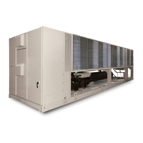
Daikin McQuay AGZ-D 25 Operating instructions

Operating and Maintenance Manual OMM 1087-1
Group: Chiller
Part Number: OMM 1087
Effective: August 2012
Supersedes: May 2012
Air-Cooled Scroll Compressor Chiller
AGZ-D 25 to 190 Tons
50 - 60-Hertz, R-410A
Software Version 251699201

2AGZ 025D through 190D OMM 1087-1
Table of Contents
Introduction........................................3
Operating/Standby Limits............................ 9
Pressure Drop Curves........................9
MicroTechIII Controller .............13
Controller Section Table of Contents......... 13
Security...................................................... 20
Unit Functions..................................20
Definitions................................................. 20
Unit Enable................................................ 21
Unit Mode Selection.................................. 22
Unit States.................................................. 22
Power Up Start Delay................................ 23
Ice Mode Start Delay................................. 23
Unit Status ................................................. 23
Evaporator Pump Control.......................... 24
LWT Target................................................ 25
Unit Capacity Control................................ 26
Unit Capacity Overrides ............................ 27
Circuit Functions..............................29
Definitions................................................. 29
Circuit Control Logic................................. 29
Pumpdown Procedure................................ 31
LowAmbient Starts ................................... 31
Circuit Status ............................................. 31
Compressor Control................................... 31
Condenser Fan Control.............................. 32
EXV Control.............................................. 34
Liquid Line Solenoid Valve....................... 35
Hot Gas Bypass Solenoid Valve ................ 35
Capacity Overrides – Limits of Operation. 35
Alarms...............................................35
Unit Fault Alarms....................................... 35
Unit ProblemAlarms................................. 37
Unit Warning Alarms..................................38
Circuit Fault Alarms...................................38
Circuit Events.............................................40
Circuit Warning Alarms..............................41
Events............................................... 41
Unit Events.................................................42
Circuit Events.............................................42
Clearing Alarms..........................................43
Using the Controller........................ 44
Navigating..................................................45
Menus.........................................................47
Optional Low Ambient Fan VFD .. 60
VFD Interface (HMI).................................61
Recommended Periodic Inspection............65
Optional BAS Interface.................. 65
Startup.............................................. 66
Operation......................................... 68
Unit Maintenance............................ 72
Planned Maintenance Schedule..................73
Service.............................................. 75
R-410A.......................................................75
Refrigerant Charging..................................76
Evaporator..................................................79
AGZ-D Troubleshooting Chart...... 80
Warranty Statement........................ 82
Cover picture: AGZ 190D, 190 nominal tons capacity.
Our facility is ISO Certified
©2012 McQuay International. Illustrations and data cover the McQuay International product at the time of publication and we reserve the right
to make changes in design and c
onstruction at anytime without notice. ™® The following are trademarks or registered trademarks of their
respective companies: BACnet from ASHRAE; LONMARK, LonTalk, LONWORKS, and the LONMARK logo are managed, granted and used by
LONMARK International under
a license granted by Echelon Corporation; Compliant Scroll from Copeland Corporation; ElectroFin from AST
ElectroFin Inc.; Modbus from Schneider Electric; FanTrol, MicroTech III, Open Choices from McQuay International. *Unit Controllers are
LONMARK certified with an optional LONWORKS communication module.

OMM 1087-1 AGZ 025D through 190D 3
Introduction
General Description
Daikin McQuay Air-Cooled Global Water
Chillers are complete, self-contained automatic
refrigerating units. Every unit is completely
assembled, factory wired, charged, and tested
(except remote evaporator option). Each unit
consists of twin air-cooled condensers with
integral subcooler sections, two tandem or
triple scroll compressors, brazed-plate or
replaceable tube, dual circuit shell-and-tube
evaporator, and complete refrigerant piping.
Liquid line components include manual liquid
line shutoff valves, sight-glass/moisture
indicators, solenoid valves, and thermal
expansion valves.
Other features include compressor crankcase
heaters, an evaporator heater for chilled water
freeze protection, , automatic compressor lead-
lag to alternate the compressor starting
sequence, and sequenced starting of
compressors.
The electrical control center includes all
equipment protection and operating controls
necessary for dependable automatic operation.
This manual covers units with Software
Version 251699201 which must be used with
firmware version 9.XX.
Installation, information is in IM 1100 (or
current, latest dash number) manual.
Nomenclature
A GZ-XXX DH
Hazard Identification Information
!
DANGER
Dangers indicate a hazardous situation which will result in death or serious injury if not avoided.
!
WARNING
Warnings indicate potentially hazardous situations, which can result in property damage, severe
personal injury, or death if not avoided.
!
CAUTION
Cautions indicate potentially hazardous situations, which can result in personal injury or equipment
damage if not avoided.
Air-Cooled
Global
Scroll Compressor
Design Vintage
Model Size
(Nominal Tons)
Application
H= Packaged Chiller

4AGZ 025D through 190D OMM 1087-1
Ambient Air Temperature
Limitations
Standard/High Ambient Panels
The maximum operating ambient temperature
for standard units is 104°F (40°C). AGZ-D
units for high ambient operation (105°F to
125°F maximum) require the addition of the
High Ambient Control Panel Option, which
includes the addition of a small fan with a
filter in the air intake to cool the control panel.
All units with the optional variable frequency
drive (VFD) low ambient fan control
automatically include the High Ambient
Control Panel Option. Operation of the VFD
generates a quantity of panel heat best
removed by use of a control panel fan.
Water Flow Limitations
The evaporator flow rates and pressure drops
shown on page 11 are for full load design
purposes in order to maintain proper unit
control. The maximum flow rate and pressure
drop are based on a 6 degree temperature drop.
Avoid higher flow rates with resulting lower
temperature drops to prevent potential control
problems resulting from very small control
bands and limited start up/shut off temperature
changes.
The minimum flow and pressure drop is based
on a full load evaporator temperature drop of
16 degrees. Evaporator flow rates below the
minimum values can result in laminar flow
causing freeze-up problems, scaling and poor
control. Flow rates above the maximum values
will result in unacceptable pressure drops and
can cause excessive erosion, potentially
leading to failure.
Variable Speed Pumping
Variable water flow involves changing the
water flow through the evaporator as the load
changes. Daikin McQuay chillers are designed
for this duty provided that the rate of change in
water flow is slow and the minimum and
maximum flow rates for the vessel are not
exceeded.
The recommended maximum change in water
flow is 10 percent of the change per minute.
When units are operated with flow rates less
than nominal (see Table 8 on page 11), the
“Evap Delta T” setpoint must be changed
proportionally to match the minimum
operating flow rate. The “Delta T” setting
should be increased by the same percentage as
the flow reduction is from the nominal rating
in order to prevent short cycling. This will
require reevaluation of “Cool LWT”, “Startup
Delta T”, and “Stop Delta T” settings as well
System Water Volume
Considerations
All chilled water systems need adequate time
to recognize a load change, respond to that
load change and stabilize without undesirable
short cycling of the compressors or loss of
temperature control. In air conditioning
systems, the potential for short cycling usually
exists when the building load falls below the
minimum chiller plant capacity or on close-
coupled systems with very small water
volumes.
Some of the things the designer should
consider when looking at water volume are the
minimum cooling load, the minimum chiller
plant capacity during the low load period and
the desired cycle time for the compressors.
Assuming that there are no sudden load
changes and that the chiller plant has
reasonable turndown, a rule of thumb of
“gallons of water volume equal to two to three
times the chilled water gpm flow rate” is often
used.
A properly designed storage tank should be
added if the system components do not provide
sufficient water volume.

OMM 1087-1 AGZ 025D through 190D 5
Glycol Solutions
The use of a glycol/water mixture in the evaporator to prevent freezing reduces system capacity and
efficiency, as well as increase pressure drop. The system capacity, required glycol solution flow rate,
and pressure drop with glycol may be calculated using Table 1.
1. Capacity –Multiply the capacity based on water by the Capacity correction factor from Table 2
through Table 5.
2. Flow – Multiply the water evaporator flow by the Flow correction factor from Table 2 through
Table 5 to determine the increased evaporator flow due to glycol.
If the flow is unknown, it can be calculated from the following equation
3. Pressure drop -- Multiply the water pressure drop from page 10 by Pressure Drop correction
factor from Table 2 through Table 5. High concentrations of propylene glycol at low temperatures
can cause unacceptably high pressure drops.
4. Power -- Multiply the water system power by Power correction factor from Table 2 - Table 5.
Test coolant with a clean, accurate glycol solution hydrometer (similar to that found in service
stations) to determine the freezing point. Obtain percent glycol from the freezing point tables below.
It is recommended that a minimum of 25% solution by weight be used for protection against corrosion
or that additional compatible inhibitors be added.
Concentrations above 35 % do not provide any additional burst protection and should be carefully
considered before using.
Table 1, Flow/Tons/Delta-T Relationship
Glycol Flow (gpm)
FactorCorrectionFlow
TDelta
glycolCapacityTons ×
×)(24
Glycol Flow (l/s) FactorCorrectionFlow
TDelta
CapacitykW ×
−×
18.4
!
WARNING
Do not use an automotive grade antifreeze. Industrial grade glycols must be used. Automotive
antifreeze contains inhibitors which will cause plating on the copper tubes within the chiller evaporator.
The type and handling of glycol used must be consistent with local codes
Table 2, Ethylene Glycol Factors for Models AGZ 025D to 130D
% E.G. Freeze Point Capacity Power Flow PD
oF oC
10
26 -3.3 0.998 0.998 1.036 1.097
20 18 -7.8 0.993 0.997 1.060 1.226
30 7 -13.9 0.987 0.995 1.092 1.369
40 -7 -21.7 0.980 0.992 1.132 1.557
50 -28 -33.3 0.973 0.991 1.182 1.791
Table 3, Propylene Glycol Factors for Models AGZ 025D to 130D
% P.G. Freeze Point Capacity Power Flow PD
o
F
o
C
10
26 -3.3 0.995 0.997 1.016 1.100
20 19 -7.2 0.987 0.995 1.032 1.211
30 9 -12.8 0.978 0.992 1.057 1.380
40 -5 -20.6 0.964 0.987 1.092 1.703
50 -27 -32.8 0.952 0.983 1.140 2.251

6AGZ 025D through 190D OMM 1087-1
Table 4, Ethylene Glycol Factors for Models AGZ 140D to 190D
% E.G.
Freeze Point
Capacity Power Flow PD
oF oC
10 26 -3.3 0.994 0.998 1.038 1.101
20
18 -7.8 0.982 0.995 1.063 1.224
30 7 -13.9 0.970 0.992 1.095 1.358
40
-7 -21.7 0.955 0.987 1.134 1.536
50 -28 -33.3 0.939 0.983 1.184 1.755
Table 5, Propylene Glycol Factors for Models AGZ 140D to 190D
% P.G.
Freeze Point
Capacity Power Flow PD
oF oC
10 26 -3.3 0.988 0.996 1.019 1.097
20 19 -7.2 0.972 0.992 1.035 1.201
30 9 -12.8 0.951 0.987 1.059 1.351
40
-5 -20.6 0.926 0.979 1.095 1.598
50 -27 -32.8 0.906 0.974 1.142 2.039
Altitude Correction Factors
Performance tables are based at sea level.
Elevations other than sea level affect the
performance of the unit. The decreased air
density will reduce condenser capacity
consequently reducing the unit's performance.
For performance at elevations other than sea
level, refer to Table 6 and Table 7.
Evaporator Temperature Drop
Factors
Performance tables are based on a 10°F (5°C)
temperature drop through the evaporator.
Adjustment factors for applications with
temperature ranges from 6°F to 16°F (3.3°C to
8.9°C) are in Table 6 and Table 7.
Temperature drops outside this 6°F to 16°F
(3.3°C to 8.9°C) range can affect the control
system's capability to maintain acceptable
control and are not recommended.
The maximum water temperature that can be
circulated through the evaporator in a non-
operating mode is 100°F (37.8°C).
Fouling Factor
Performance tables are based on water with a
fouling factor of:
)/0176.0(/0001.0 22 kWCmorBTUFhrft °×°××
per ARI 550/590-98.
As fouling is increased, performance
decreases. For performance at other than
0.0001 (0.0176) fouling factor, refer to Table 6
or Table 7.
Foreign matter in the chilled water
system will adversely affect the heat
transfer capability of the evaporator
and could increase the pressure drop
and reduce the water flow. Maintain
proper water treatment to provide
optimum unit operation.

OMM 1087-1 AGZ 025D through 190D 7
Table 6, Capacity and Power Derates, Models AGZ 025D to 130D
Altitude Chilled Water Delta
T Fouling Factor
0.0001 (0.0176) 0.00025 (0.044) 0.00075 (0.132) 0.00175 (0.308)
°F °C Cap. Power Cap. Power Cap. Power Cap. Power
Sea
Level
6 3.3 0.978 0.993 0.975 0.991 0.963 0.987 0.940 0.980
8 4.4 0.989 0.996 0.986 0.994 0.973 0.990 0.950 0.983
10 5.6 1.000 1.000 0.996 0.999 0.984 0.994 0.961 0.987
12 6.7 1.009 1.003 1.005 1.001 0.993 0.997 0.969 0.990
14 7.7 1.018 1.004 1.014 1.003 1.002 0.999 0.978 0.991
16 8.9 1.025 1.007 1.021 1.006 1.009 1.001 0.985 0.994
2000 feet
6 3.3 0.977 1.001 0.973 1.000 0.961 0.996 0.938 0.989
8 4.4 0.987 1.006 0.984 1.004 0.971 1.000 0.948 0.993
10 5.6 0.998 1.009 0.995 1.007 0.982 1.003 0.959 0.996
12 6.7 1.007 1.011 1.004 1.010 0.991 1.006 0.967 0.998
14 7.7 1.014 1.014 1.011 1.013 0.998 1.009 0.974 1.001
16 8.9 1.022 1.016 1.018 1.014 1.005 1.010 0.981 1.003
4000 feet
6 3.3 0.973 1.011 0.970 1.010 0.957 1.006 0.935 0.998
8 4.4 0.984 1.014 0.980 1.013 0.968 1.009 0.945 1.001
10 5.6 0.995 1.019 0.991 1.017 0.979 1.013 0.955 1.005
12 6.7 1.004 1.021 1.000 1.020 0.987 1.016 0.964 1.008
14 7.7 1.011 1.024 1.007 1.023 0.994 1.018 0.971 1.011
16 8.9 1.018 1.027 1.014 1.026 1.002 1.021 0.978 1.014
6000 feet
6 3.3 0.969 1.021 0.966 1.020 0.954 1.016 0.931 1.008
8 4.4 0.980 1.026 0.977 1.024 0.964 1.020 0.942 1.013
10 5.6 0.989 1.029 0.986 1.027 0.973 1.023 0.950 1.015
12 6.7 0.998 1.033 0.995 1.031 0.982 1.027 0.959 1.020
14 7.7 1.007 1.036 1.004 1.034 0.991 1.030 0.967 1.022
16 8.9 1.014 1.037 1.011 1.036 0.998 1.031 0.974 1.024

8AGZ 025D through 190D OMM 1087-1
Table 7, Capacity and Power Derates, Models AGZ 140D to 190D
Altitude Chilled Water
Delta T Fouling Factor
0.0001 (0.0176) 0.00025 (0.044) 0.00075 (0.132) 0.00175 (0.308)
°F °C Cap. Power Cap. Power Cap. Power Cap. Power
Sea
Level
6 3.3 0.990 0.997 0.976 0.994 0.937 0.983 0.868 0.964
8 4.4 0.994 0.998 0.981 0.995 0.942 0.984 0.872 0.965
10 5.6 1.000 1.000 0.987 0.996 0.947 0.986 0.877 0.967
12 6.7 1.005 1.001 0.991 0.997 0.951 0.986 0.881 0.968
14 7.7 1.009 1.002 0.995 0.998 0.955 0.987 0.884 0.968
16 8.9 1.013 1.004 1.000 1.000 0.960 0.989 0.889 0.970
2000 feet
6 3.3 0.987 1.005 0.974 1.002 0.934 0.991 0.865 0.972
8 4.4 0.992 1.006 0.979 1.003 0.940 0.992 0.870 0.973
10 5.6 0.997 1.008 0.984 1.004 0.944 0.994 0.875 0.975
12 6.7 1.002 1.009 0.989 1.005 0.949 0.994 0.879 0.975
14 7.7 1.007 1.011 0.993 1.007 0.953 0.996 0.883 0.977
16 8.9 1.011 1.012 0.998 1.008 0.958 0.997 0.887 0.978
4000 feet
6 3.3 0.985 1.014 0.972 1.010 0.933 0.999 0.864 0.980
8 4.4 0.991 1.015 0.977 1.012 0.938 1.001 0.869 0.981
10 5.6 0.995 1.016 0.982 1.013 0.943 1.002 0.873 0.982
12 6.7 1.000 1.018 0.987 1.014 0.947 1.003 0.877 0.984
14 6.8 1.005 1.019 0.991 1.015 0.951 1.004 0.881 0.985
16 8.9 1.009 1.021 0.995 1.017 0.955 1.006 0.884 0.987
6000 feet
6 3.3 0.982 1.023 0.969 1.020 0.930 1.009 0.861 0.989
8 4.4 0.988 1.025 0.975 1.022 0.935 1.010 0.866 0.991
10 5.6 0.992 1.026 0.979 1.022 0.940 1.011 0.870 0.992
12 6.7 0.997 1.028 0.984 1.024 0.944 1.013 0.875 0.994
14 7.7 1.002 1.029 0.989 1.025 0.949 1.014 0.879 0.995
16 8.9 1.006 1.031 0.992 1.027 0.952 1.016 0.882 0.996
8000 feet
6 3.3 0.979 1.034 0.966 1.031 0.927 1.019 0.859 1.000
8 4.4 0.984 1.036 0.971 1.032 0.932 1.021 0.863 1.002
10 5.6 0.990 1.037 0.976 1.033 0.937 1.022 0.868 1.002
12 6.7 0.993 1.039 0.980 1.035 0.941 1.024 0.871 1.004
14 7.7 0.998 1.041 0.985 1.037 0.945 1.026 0.875 1.006
16 8.9 1.003 1.041 0.990 1.038 0.950 1.026 0.879 1.007
Evaporator Freeze Protection
Evaporator freeze-up can be a concern in the
application of air-cooled water chillers. To
protect against freeze-up, insulation and an
electric heater cable are furnished with the
unit. This protects the evaporator down to -
20°F (-29°C) ambient air temperature.
Although the evaporator is equipped with
freeze protection, it does not protect water
piping external to the unit or the evaporator
itself if there is a power failure or heater cable
burnout. Consider the following
recommendations for additional protection.
1. If the unit will not be operated during the
winter, drain evaporator and chilled water
piping and flush with glycol. Drain and
vent connections are provided on the
evaporator to ease draining.
2. Add a glycol solution to the chilled water
system to provide freeze protection.
Freeze point should be approximately ten
degrees below minimum design ambient
temperature.
3. The addition of thermostatically controlled
heat and insulation to exposed piping.
4. Continuous circulation of water through
the chilled water piping and evaporator.
The evaporator heater cable is factory wired to
the 115-volt circuit in the control box. This
power should be supplied from a separate
source, but it can be supplied from the control
circuit. Operation of the heater cable is

OMM 1087-1 AGZ 025D through 190D 9
automatic through the ambient sensing
thermostat that energizes the evaporator heater
cable for protection against freeze-up. Unless
the evaporator is drained in the winter, the
disconnect switch to the evaporator heater
must not be open.
Operating/Standby Limits
•Maximum standby ambient air temperature, 130° F (55° C)
•Maximum operating ambient air temperature 105°F (40.6°C)
•Minimum operating ambient temperature (standard), 35° F (2° C)
•Minimum operating ambient temperature (with optional low-ambient control), -10° F (-23.3°C)
•Leaving chilled water temperature, 40°F to 60°F (4.4° C to 15.6° C)
•Leaving chilled fluid temperatures (with anti-freeze), 15° F to 60° F (-9.4°C to 15.6°C)
•Chilled water Delta-T range, 6 degrees F to 16 degrees F (3.3 degrees C to 8.9 degrees C)
•Part load minimum flow for variable flow systems, varies with unit size; see Table 8 on page 11.
•Maximum operating inlet fluid temperature, 76° F (24° C)
•Maximum non-operating inlet fluid temperature, 100°F (38°C).
Pressure Drop Curves
Evaporator pressure drop curves on the
following page. They apply to either packaged
or remote evaporator applications. Figure 1,
Evaporator Pressure Drops. See following page
for curve cross-reference on the next page
contains the evaporator reference letter and the
minimum and maximum flows allowed for
each unit.
Occasionally the same evaporator is used on
multiple units resulting in overlapping lines.
The minimum and maximum flows for a given
unit will be at the point where the unit
reference number appears.

10 AGZ 025D through 190D OMM 1087-1
Figure 1, Evaporator Pressure Drops. See following page for curve cross-reference
See following page for curve cross-reference and min/max flow rates.
AGZ Water Pressure Drop
A
B
B
C
C
D
D
E
E
F
F
G
G
H
H
I
I
J
J
K
K
L
L
M
M
N
N
O
O
P
P
Q
Q
R
R
S
S
T
T
U
U
A
1
10
100
10 100 1000
Flow Rate (gpm)
Dp (ft)
A
B
C
D
E
F
G
H
I
J
K
L
M
N
O
P
Q
R
S
T
U

OMM 1087-1 AGZ 025D through 190D 11
Table 8, Curve Cross-Reference, Min/Nominal/Max Flows
Curve
Ref.
AGZ
Unit
Model
Evaporator
Type
Minimum Flow Rate
Nominal Flow Rate
Maximum Flow Rate
Inch-Pound
S.I.
Inch-Pound
S.I.
Inch-Pound
S.I.
gpm DP
ft.
lps DP
kpa
gpm DP
ft.
lps DP
kpa
gpm DP
ft.
lps DP
kpa
A
025D
Brazed Plate
41.3
3.7
2.6
11.0
66.0
9.0
4.2
26.8
105.6
22.0
6.7
65.5
A 030D
47.4
4.8
3.0
14.3
75.8
11.7
4.8
34.9
121.3
28.6
7.7
85.2
B 035D
51.8
5.2
3.3
15.5
82.8
12.7
5.2
37.8
132.5
31.0
8.4
92.4
C
040D
56.4
5.2
3.6
15.5
90.2
12.7
5.7
37.8
144.4
31.0
9.1
92.4
D
045D
63.5
5.1
4.0
15.1
101.5
12.4
6.4
37.0
162.4
30.3
10.2
90.3
E 050D 72.2 5.5 4.6 16.5 115.4 13.5 7.3 40.2 184.7 33.0 11.7 98.3
F 055D
77.4
5.2
4.9
15.5
123.8
12.7
7.8
37.8
198.1
31.0
12.5
92.4
G 060D
84.2
5.1
5.3
15.3
134.6
12.5
8.5
37.3
215.4
30.5
13.6
91.0
H
065D
87.2
4.5
5.5
13.4
139.4
11.0
8.8
32.8
223.1
26.9
14.1
80.1
I
070D
96.2
5.4
6.1
16.2
153.8
13.3
9.7
39.6
246.1
32.5
15.5
96.8
J
075D
109.7
5.3
6.9
15.7
175.4
12.9
11.1
38.4
280.7
31.5
17.7
93.9
K 080D
121.7
5.2
7.7
15.6
194.6
12.8
12.3
38.1
311.4
31.3
19.7
93.2
L 090D
132.3
5.4
8.3
16.1
211.7
13.2
13.4
39.3
338.7
32.2
21.4
96.1
M
100D
149.7
5.2
9.4
15.4
239.5
12.6
15.1
37.5
383.2
30.8
24.2
91.7
N
110D
159.2
5.3
10.0
15.9
254.6
13.0
16.1
38.7
407.4
31.8
25.7
94.6
O
125D
175.7
5.4
11.1
16.1
281.0
13.2
17.7
39.3
449.7
32.2
28.4
96.1
P 130D
194.3
5.5
12.3
16.5
310.8
13.5
19.6
40.2
497.3
33.0
31.4
98.3
Q 140D
Shell-and-
Tube
204.3
4.3
12.9
12.9
326.9
10.6
20.6
31.6
523.0
25.9
33.0
77.2
R
160D
230.0
5.9
14.5
17.7
367.9
14.5
23.2
43.2
588.7
35.4
37.1
105.5
S
180D
258.3
7.4
16.3
22.0
413.3
18.0
26.1
53.6
661.2
44.0
41.7
131.0
T
190D
270.2
9.4
17.0
28.0
432.2
22.0
27.3
65.6
691.6
53.7
43.6
160.1

12 AGZ 025D through 190D OMM 1087-1
Figure 2, Typical Field Control Wiring

OMM 1087-1 AGZ 025D through 190D 13
MicroTechIII Controller
Controller Section Table of Contents
Overview........................................................................................................................14
Controller Inputs and Outputs .......................................................................................14
Setpoints ........................................................................................................................16
Security..........................................................................................................................20
Unit Control Functions..................................................................................................20
Unit Enable....................................................................................................................21
Unit Mode Selection......................................................................................................22
Unit States......................................................................................................................22
Start Delays....................................................................................................................23
Evaporator Pump Control..............................................................................................24
Leaving Water Temperature (LWT) Reset/Target .........................................................25
Unit Capacity Control....................................................................................................26
Unit Capacity Overrides……………………………………………………………….27
Circuit Control Functions..............................................................................................29
Circuit Control Logic.....................................................................................................29
Pumpdown Procedure....................................................................................................31
Compressor Control.......................................................................................................31
Condenser Fan Control..................................................................................................32
EXV Control..................................................................................................................34
Liquid Line Solenoid.....................................................................................................35
Hot Gas Bypass Solenoid ..............................................................................................35
Alarms............................................................................................................................35
Events…………………………………………………………………………....…….41
ClearingAlarms.............................................................................................................43
Using the Controller…………………………………………………………………...44

14 AGZ 025D through 190D OMM 1087-1
Overview
The MicroTech® III controller’s state-of-the-art design not only permits the chiller to run more
efficiently, but also can simplify troubleshooting if a system failure occurs. Every MicroTech IIII
controller is programmed and tested prior to shipment to facilitate start-up.
Operator-friendly
The MicroTech III controller menu structure is separated into three distinct categories that provide the
operator or service technician with a full description of :
1. current unit status
2. control parameters
3. alarms. Security protection prevents unauthorized changing of the setpoints and control parameters.
MicroTech III control continuously performs self-diagnostic checks, monitoring system temperatures,
pressures and protection devices, and will automatically shut down a compressor or the entire unit
should a fault occur. The cause of the shutdown will be retained in memory and can be easily
displayed in plain English for operator review. The MicroTech III chiller controller will also retain
and display the date/time the fault occurred. In addition to displaying alarm diagnostics, the
MicroTech III chiller controller also provides the operator with a warning of limit (pre-alarm)
conditions.
Controller Inputs and Outputs
Main Controller
Table 9, Analog Inputs
#
Description
Type
Expected Range
AI1
Evaporator EWT
NTC 10k
340 to 300k Ω
AI2
Evaporator LWT
NTC 10k
340 to 300k Ω
AI3 Outside Ambient
Temperature
NTC 10k 340 to 300k Ω
X1
Demand Limit
4-20 mA
1 to 23 mA
X4
LWT Reset
4-20 mA
1 to 23 mA
Table 10, Analog Outputs
#
Description
Output Type
Range
X5
Circuit 1 Fan VFD Speed
Voltage
0 to 10 volts
X6
Circuit 2 Fan VFD Speed
Voltage
0 to 10 volts
Table 11, Digital Inputs
Description
Signal Off
Signal On
DI1
External Alarm/Event
External Fault
No External Fault
DI2
Evaporator Flow Switch
No Flow
Flow
DI3 Double Set Point/ Mode
Switch
See sections on Unit Mode Selection and LWT
Target
DI4
Remote Switch
Remote Disable
Remote Enable
DI5
Unit Switch
Unit Disable
Unit Enable

OMM 1087-1 AGZ 025D through 190D 15
Table 12, Digital Outputs
Description
Output Off
Output On
DO1
Evaporator Water Pump 1
Pump Off
Pump On
DO2
Alarm Indicator
Alarm Not Active
Alarm Active
DO3
Circuit 1 Fan Output 1
Fan(s) Off
Fan(s) On
DO4
Circuit 1 Fan Output 2
Fan(s) Off
Fan(s) On
DO5
Circuit 1 Fan Output 3
Fan(s) Off
Fan(s) On
DO6
Circuit 1 Fan Output 4
Fan(s) Off
Fan(s) On
DO7
Circuit 2 Fan Output 1
Fan(s) Off
Fan(s) On
DO8
Circuit 2 Fan Output 2
Fan(s) Off
Fan(s) On
DO9
Circuit 2 Fan Output 3
Fan(s) Off
Fan(s) On
DO10
Circuit 2 Fan Output 4
Fan(s) Off
Fan(s) On
Compressor Module 1
Analog Inputs
Description
Signal Type
Expected Range
X1
Circuit 1 Suction Temperature
NTC 10k
340 to 300k Ω
X2
Circuit 1 Evaporator Pressure
Voltage
0.4 to 4.6 volts
X4
Circuit 1 Condenser Pressure
Voltage
0.4 to 4.6 volts
Digital Inputs
Description
Signal Off
Signal On
X6
Circuit 1 Switch
Circuit Disable
Circuit Enable
X7
Circuit 1 MHP Switch
Fault
No fault
X8
Circuit 1 Motor Protection
Fault
No fault
DI1
Circuit 1 (or Unit) PVM/GFP
Fault
No fault
Digital Outputs
Description
Output Off
Output On
DO1
Compressor #1
Compressor Off
Compressor On
DO2
Compressor #3
Compressor Off
Compressor On
DO3
Compressor #5
Compressor Off
Compressor On
DO4
Evaporator Water Pump 2
Pump Off
Pump On
DO5
Circuit 1 Hot Gas Bypass SV
Solenoid Closed
Solenoid Open
DO6
Circuit 1 Liquid Line SV
Solenoid Closed
Solenoid Open
Compressor Module 2
Analog Inputs
Description
Signal Type
Expected Range
X1
Circuit 2 Suction Temperature
NTC 10k
340 to 300k Ω
X2
Circuit 2 Evaporator Pressure
Voltage
0.4 to 4.6 volts
X4
Circuit 2 Condenser Pressure
Voltage
0.4 to 4.6 volts
Digital Inputs
Description
Signal Off
Signal On
X6
Circuit 2 Switch
Circuit Disable
Circuit Enable
X7
Circuit 2 MHP Switch
Fault
No fault
X8
Circuit 2 Motor Protection
Fault
No fault
DI1
Circuit 2 PVM/GFP
Fault
No fault
Note: The Motor Protection and MHP input signal are wired in series. If Motor Protection input is
open, MHP Switch input will also be open.

16 AGZ 025D through 190D OMM 1087-1
Digital Outputs
Description
Output Off
Output On
DO1
Compressor #2
Compressor Off
Compressor On
DO2
Compressor #4
Compressor Off
Compressor On
DO3
Compressor #6
Compressor Off
Compressor On
DO5
Circuit 2 Hot Gas Bypass SV
Solenoid Closed
Solenoid Open
DO6
Circuit 2 Liquid Line SV
Solenoid Closed
Solenoid Open
EXV Module 1 and 2
These modules will be used only when the expansion valve type is electronic.
Digital Outputs
Description
Output Off
Output On
DO1
Circuit 1 Fan Output 5
Fan(s) Off
Fan(s) On
Stepper Motor Output
Description
M1+, M1-
EXV Stepper Coil 1
M2+, M2-
EXV Stepper Coil 2
Sensor Information
Temperature
All temperature sensors will be McQuay part number 1934146.
Pressure
Pressure inputs will be read using 0 to 5 volt ratiometric sensors. Nominal voltage range will be 0.5
to 4.5 volts.
Pressure on the low side will be measured using McQuay part number 331764501.
Pressure on the high side will be measured using McQuay part number 331764601.
Actuator Information
•The electronic expansion valves used are McQuay part number 33038620X. These valves are
Sporlan supplied and all use the same bipolar stepper motor.
Setpoints
Setpoints are stored in permanent memory.
SetPoint Tables
Setpoints are initially set to the values in the Default column, and can be adjusted to any value in the
Range column.

OMM 1087-1 AGZ 025D through 190D 17
Unit Level Setpoints:
Description
Default
Range
Mode/Enabling
Unit Enable Enable Disable, Enable
Network Unit Enable
Disable
Disable, Enable
Control source
Local
Local, Network
Available Modes Cool Cool, Cool w/Glycol, Cool/Ice w/Glycol
Ice, Test
Network Mode Command
Cool
Cool, Ice
Staging and Capacity Control
Cool LWT 1
7°C (44.6°F)
See Auto Adjusted Ranges, page 18
Cool LWT 2
7°C (44.6°F)
See Auto Adjusted Ranges, page 18
Ice LWT
4.4°C (39.9°F)
-9.5 to 4.4 °C (14.9 to 39.9 °F)
Network Cool Set Point
7°C (44.6°F)
See Auto Adjusted Ranges, page 18
Network Ice Set Point
4.4°C (39.9°F)
-9.5 to 4.4 °C (14.9 to 39.9 °F)
Startup Delta T
5.6°C (10.1°F)
0.6 to 8.3 °C (1.1 to 14.9 °F)
Shut Down Delta T
0.3°C (0.5°F)
0.3 to 1.7 °C (0.5 to 3.1 °F)
Max Pulldown
0.6°C/min (1.1°F/min)
0.1 to 2.7 °C/min (0.2 to 4.9 °F/min)
Nominal Evap Delta T
5.6 °C (10.1°F)
3.3 to 8.9 °C (5.9 to 16 °F)
Demand Limit Enable
Off
Off, On
Network Capacity Limit
100%
0 to 100%
LWT Reset Enable
Off
Off, On
Configuration
Power Input
Single Point
Single Point, Multi Point
Evap Control #1 Only #1 Only, #2 Only, Auto,
#1 Primary, #2 Primary
Number of Compressors
4
4,6
Expansion Valve Type
Thermal
Thermal, Electronic
Fan VFD enable
No
No, Yes
Number of fans
4
4,6,8,10,12,14
Timers
Evap Recirc Timer
30
15 to 300 seconds
Stage Up Delay
240 sec
120 to 480 sec
Stage Down Delay
30 sec
20 to 60 sec
Stage Delay Clear
No
No, Yes
Start-start timer
15 min
10-60 minutes
Stop-start timer
5 min
3-20 minutes
Clear Cycle Timers
No
No, yes
Ice Time Delay
12
1-23 hours
Clear Ice Timer
No
No,Yes
Sensor Offsets
Evap LWT sensor offset
0°C (0°F)
-5.0 to 5.0 °C (-9.0 to 9.0 °F)
Evap EWT sensor offset
0°C (0°F)
-5.0 to 5.0 °C (-9.0 to 9.0 °F)
OAT sensor offset
0°C (0°F)
-5.0 to 5.0 °C (-9.0 to 9.0 °F)
Alarm Settings
Low Evap Pressure Unload
689.5 KPA(100 PSI)
See section 5.1.1
Low Evap Pressure Hold
696.4 KPA(101 PSI)
See section 5.1.1
High Condenser Pressure
4240 KPA(615 PSI)
3310 to 4275 KPA (480 to 620 PSI)
Continued next page.

18 AGZ 025D through 190D OMM 1087-1
Description
Default
Range
High Condenser Pressure Unload
4137 KPA(600 PSI)
3241 to 4137 KPA (470 to 600 PSI)
Evaporator Flow Proof
5 sec
5 to 15 sec
Recirculate Timeout
3 min
1 to 10 min
Evaporator Water Freeze
2.2°C (36°F)
See Auto Adjusted Ranges, page 18
Low OAT Start Time
165 sec
150 to 240 sec
External Alarm Configuration
Event
Event, Alarm
Clear Alarms
Off
Off, On
Network Clear Alarms
Off
Off, On
Circuit Setpoints (exist individually for each circuit):
Description Default Range
Mode/Enabling
Circuit mode
Enable
Disable, Enable, Test
Compressor 1 Enable
Enable
Enable, Disable
Compressor 2 Enable
Enable
Enable, Disable
Compressor 3 Enable
Enable
Enable, Disable
Network Compressor 1 Enable
Enable
Enable, Disable
Network Compressor 2 Enable
Enable
Enable, Disable
Network Compressor 3 Enable
Enable
Enable, Disable
EXV control
Auto
Auto, manual
EXV position See Special Setpoints,
page 18
0% to 100%
Suction SH Target
5.56°C (10°° )
4.44 to 6.67 °C (8 to 12 °F)
Max Evap Pressure
1076 KPA(156.1 PSI)
979 to 1172 KPA (142 to 170 PSI)
Condenser
Condenser Target 100%
37.8°C (100°F)
32.22 to 48.9 °C (90 to 120 °F)
Condenser Target 67%
32.2°C (90°F)
32.22 to 48.9 °C (90 to 120 °F)
Condenser Target 50%
32.2°C (90°F)
29.44 to 43.3 °C (85 to 110 °F)
Condenser Target 33%
29.4°C (85°F)
29.44 to 43.3 °C (85 to 110 °F)
VFD Max Speed
100%
90 to 110%
VFD Min Speed
25%
25 to 60%
Fan Stage Up Deadband 1
8.33°C (15°F)
8.33 to 13.89 °C (15 to 25 °F)
Fan Stage Up Deadband 2
5.56°C (10°F)
5.56 to 8.33 °C (10 to 15 °F)
Fan Stage Up Deadband 3
5.56°C (10°F)
5.56 to 8.33 °C (10 to 15 °F)
Fan Stage Up Deadband 4
5.56°C (10°F)
5.56 to 8.33 °C (10 to 15 °F)
Fan Stage Down Deadband 1
11.11°C (20°F)
8.33 to11.11 °C (15 to 20 °F)
Fan Stage Down Deadband 2
11.11°C (20°F)
8.33 to11.11 °C (15 to 20 °F)
Fan Stage Down Deadband 3
8.33 °C (15 °F)
5.56 to 8.33 °C (10 to 15 °F)
Fan Stage Down Deadband 4
5.56 °C (10 °F)
3.33 to 5.56 °C (6 to 10 °F)
Sensor Offsets
Evap pressure offset
0 KPA (0 PSI)
-100 to 100 KPA (-14.5 to 14.5 PSI)
Cond pressure offset
0 KPA (0 PSI)
-100 to 100 KPA (-14.5 to 14.5 PSI)
Suction temp offset
0°C (0°F)
-5.0 to 5.0 °C (-9.0 to 9.0 °F)
Note – Condenser Target 67% and Condenser Target 33% will be available only when Number of
Compressors is 6. Condenser Target 50% will be available only when Number of Compressors is 4.
Auto Adjusted Ranges
Some settings have different ranges of adjustment based on other settings:

OMM 1087-1 AGZ 025D through 190D 19
Cool LWT 1, Cool LWT 2, and Network Cool Set Point
Available Mode Selection
Range
Without Glycol
4.4 to 15.6 °C (39.9 to 60.1 °F)
With Glycol
-9.5 to 15.6 °C (14.9 to 60.1 °F)
Evaporator Water Freeze
Available Mode Selection
Range
Without Glycol
2.2 to 5.6 °C (36 to 42.1 °F)
With Glycol
-10.8 to 5.6 °C (12.6 to 42.1 °F)
Low Evaporator Pressure Hold and Unload
Available Mode Selection
Range
Without Glycol
669 to 793 KPA (97 to 115 PSI)
With Glycol
407 to 793 KPA (59 to 115 PSI)
Special Set Point Operations
The following setpoints are not changeable unless the unit switch is off:
•Available Modes
•Number of Compressors
•Expansion Valve Type
•Number of Fans
•Fan VFD Enable
The Circuit Mode setpoints should not be changeable unless the corresponding circuit switch is off.
The Compressor Enable setpoints should not be changeable unless the corresponding compressor is
not running.
EXV Position set point on each circuit follows the actual EXV position while EXV Control = Auto.
When EXV Control = Manual, the position set point should be changeable.
The Clear Alarms and Network Clear Alarms settings are automatically set back to Off after being On
for 1 second.

20 AGZ 025D through 190D OMM 1087-1
Security
All setpoints are protected using passwords.A four-digit password provides operator access to changeable
parameters. Service level passwords are reserved for authorized service personnel. .
Operator password: 5321
Entering Passwords
Passwords are entered on the first screen on the unit controller,
If the wrong password is entered, a message will temporarily appear stating this. If no valid password is
active the active password level displays “none”.
Editing Setpoints
After a valid password has been entered at the unit controller, setpoints may be changed. If the operator
attempts to edit a setpoint for which the necessary password level is not active, no action will be taken.
Once a password has been entered, it remains valid for 10 minutes after the last key-press on the unit
controller.
Unit Functions
Definitions
The calculations in this section are used in unit level and circuit control logic.
LWT Slope
LWT slope is calculated such that the slope represents the estimated change in LWT over a time frame of one
minute.
Pulldown Rate
The slope value calculated above will be a negative value as the water temperature is dropping. A pulldown
rate is calculated by inverting the slope value and limiting to a minimum value of 0°C/min.
LWT Error
LWT error is calculated as:
LWT – LWT target
Table of contents
Other Daikin McQuay Chiller manuals
Popular Chiller manuals by other brands

McQuay
McQuay ACZ 055A Installation, operation and maintenance manual

Trane
Trane RTAA installation instructions

Nemco
Nemco 9020 Operating and maintenance instructions

Quantech
Quantech QTC40160 Installation operation & maintenance

Kaysun
Kaysun KEM-05 DVN1 Installation & owner's manual

Modena
Modena UC Series manual

McQuay
McQuay AGR 055AS Installation, operation and maintenance manual

Yamato
Yamato CA301 instruction manual

Carrier
Carrier 17DK Operating and maintenance instructions

Trane
Trane ECOWISE RTAF SE Installation operation & maintenance

SMC Networks
SMC Networks HRZD020-WS-WS Operation manual

Elkay
Elkay ECU8 1H Series Installation, care & use manual