Table of contents
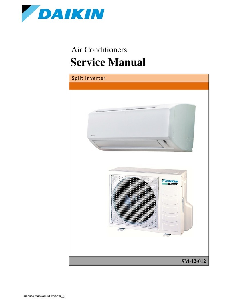
Service manual
3
ATXP20~35L2V1B + FTXP20~71L2V1B + ARXP20~35L2V1B +
RXP20~71L2V1B
Split Comfora R32
ESIE18-01 – 2019.02
Table of contents
1 Troubleshooting 4
1.1 To display the error code on the user interface......................... 4
1.2 To reset the error code via remote controller ............................ 4
1.3 To reset the error code via outdoor unit .................................... 4
1.4 To perform a test run................................................................. 4
1.4.1 To perform a test run in winter season ....................... 4
1.5 Error based troubleshooting ...................................................... 4
1.5.1 A1-00 – PCB abnormality ........................................... 4
1.5.2 A5-00 – Freeze-up protection / heating peak cut
control ......................................................................... 4
1.5.3 A6-00 – Indoor unit fan motor abnormality.................. 5
1.5.4 C4-00 – Indoor heat exchanger thermistor
abnormality ................................................................. 5
1.5.5 C9-00 – Room thermistor abnormality ........................ 5
1.5.6 E1-00 – PCB defect .................................................... 5
1.5.7 E3-00 – High pressure switch abnormality ................. 6
1.5.8 E5-00 – Overheat of inverter compressor motor......... 6
1.5.9 E6-00 – Compressor startup defect............................ 6
1.5.10 E7-00 – Fan lock abnormality ..................................... 7
1.5.11 E8-00 – Input overvoltage abnormality ....................... 7
1.5.12 EA-00 – Cooling/Heating switch abnormality.............. 7
1.5.13 F3-00 – Discharge pipe temperature stop
abnormality ................................................................. 7
1.5.14 F6-00 – Stop due to cooling high pressure ................. 8
1.5.15 F8-00 – System shutdown due to compressor
internal temperature abnormality ................................ 8
1.5.16 H0-00 – Current sensor abnormality........................... 8
1.5.17 H3-00 – High pressure switch defect .......................... 9
1.5.18 H6-00 – Location detection sensor abnormality.......... 9
1.5.19 H8-00 – Compressor input abnormality ...................... 9
1.5.20 H9-00 – Outdoor air thermistor abnormality................ 10
1.5.21 J3-00 – Discharge pipe thermistor dislocation
abnormality ................................................................. 10
1.5.22 J6-00 – Outdoor heat exchanger thermistor
abnormality ................................................................. 10
1.5.23 L3-00 – Electrical component temperature
abnormality ................................................................. 10
1.5.24 L4-00 – Fin temperature increase abnormality ........... 10
1.5.25 L5-00 – Output over current abnormality .................... 11
1.5.26 P4-00 – Fin thermistor abnormality............................. 11
1.5.27 U0-00 – Shortage of refrigerant .................................. 11
1.5.28 U2-00 – Main circuit voltage abnormality.................... 12
1.5.29 U4-00 – Indoor/outdoor transmission abnormality ...... 12
1.5.30 UA-00 – Indoor/outdoor combination abnormality ...... 12
1.6 Symptom based troubleshooting............................................... 14
1.6.1 Operation does not start ............................................. 14
1.6.2 Operation sometimes stops ........................................ 14
1.6.3 Operation starts but the unit does not cool/heat ......... 14
1.6.4 Operating noise and vibrations ................................... 15
1.6.5 Abnormal high pressure.............................................. 15
1.6.6 Abnormal low pressure ............................................... 15
1.6.7 Indoor fan starts operating but the compressor does
not operate.................................................................. 16
1.6.8 Operation starts and the unit stops immediately......... 16
1.6.9 Operation stops, unit cannot start for a while.............. 16
1.6.10 Unit discharges white mist .......................................... 16
1.6.11 Swing flap does not operate ....................................... 17
2 Components 18
2.1 4-way valve ............................................................................... 18
2.1.1 Checking procedures .................................................. 18
2.1.2 Repair procedures ...................................................... 19
2.2 Compressor............................................................................... 20
2.2.1 Checking procedures .................................................. 20
2.2.2 Repair procedures ...................................................... 22
2.3 Expansion valve ........................................................................ 23
2.3.1 Checking procedures ................................................... 23
2.3.2 Repair procedures ....................................................... 24
2.4 High pressure switch .................................................................. 26
2.4.1 Checking procedures ................................................... 26
2.4.2 Repair procedures ....................................................... 26
2.5 Indoor unit fan motor .................................................................. 27
2.5.1 Checking procedures ................................................... 27
2.5.2 Repair procedures ....................................................... 28
2.6 Indoor unit PCB .......................................................................... 29
2.6.1 Checking procedures ................................................... 29
2.6.2 Repair procedures ....................................................... 30
2.7 Inverter PCB............................................................................... 31
2.7.1 Checking procedures ................................................... 31
2.7.2 Repair procedures ....................................................... 32
2.8 Main PCB ................................................................................... 32
2.8.1 Checking procedures ................................................... 32
2.8.2 Repair procedures ....................................................... 33
2.9 Outdoor unit fan motor ............................................................... 34
2.9.1 Checking procedures ................................................... 34
2.9.2 Repair procedures ....................................................... 35
2.10 Plate work................................................................................... 35
2.10.1 Outdoor unit ................................................................. 35
2.10.2 Indoor unit .................................................................... 38
2.11 Reactor ....................................................................................... 40
2.11.1 Checking procedures ................................................... 40
2.11.2 Repair procedures ....................................................... 40
2.12 Swing flap motor......................................................................... 41
2.12.1 Checking procedures ................................................... 41
2.12.2 Repair procedures ....................................................... 41
2.13 Thermistors ................................................................................ 41
2.13.1 Refrigerant thermistors ................................................ 42
2.13.2 Other thermistors ......................................................... 44
3 Third party components 44
3.1 Power supply.............................................................................. 44
3.1.1 Checking procedures ................................................... 44
3.1.2 Repair procedures ....................................................... 44
3.2 Refrigerant circuit ....................................................................... 45
3.2.1 Checking procedures ................................................... 45
3.2.2 Repair procedures ....................................................... 46
3.3 External factors .......................................................................... 47
3.3.1 Checking procedures ................................................... 47
3.3.2 Repair procedures ....................................................... 47
4 Maintenance 48
4.1 To clean the outdoor unit heat exchanger.................................. 48
4.2 To clean the indoor unit heat exchanger .................................... 48
4.3 To clean the air filters ................................................................. 48
5 Technical data 49
5.1 Detailed information setting mode.............................................. 49
5.1.1 Detailed information setting mode: Indoor unit ............ 49
5.1.2 Detailed information setting mode: Outdoor unit.......... 49
5.1.3 Detailed information setting mode: Remote controller . 49
5.2 Wiring diagram ........................................................................... 50
5.2.1 Wiring diagram: Indoor unit.......................................... 50
5.2.2 Wiring diagram: Outdoor unit ....................................... 51
5.3 Piping diagram ........................................................................... 52
5.3.1 Piping diagram: Indoor unit .......................................... 52
5.3.2 Piping diagram: Outdoor unit ....................................... 54
5.4 Component overview.................................................................. 57
5.4.1 Component overview: Indoor unit ................................ 57
5.4.2 Component overview: Outdoor unit ............................. 58
5.5 Field information report .............................................................. 59
5.6 Service tools............................................................................... 62
5.7 Field settings .............................................................................. 63
5.7.1 Field settings: Indoor unit............................................. 63
5.7.2 Field settings: Outdoor unit .......................................... 64
