4
Installation
Procedure Installation
PIM00132
Proper use results in power saving
Installation
Procedure
Before
Operation
Useful
Functions
Maintenance
Troubleshooting
Optional
Functions
Operating
Procedure
Installation
Models
Menu
Series
AKZJ188
AKZJ358
AKZJ458
AKZJ568
AKZJ908
Handling
Optional Parts
Maintenance
Immersion type
Instruction Manual
AKZJ8 Series
DAIKIN Oil Cooling Unit
(“OILCON”)
Built-inbreaker
model
Different-voltage
model
CEmodel
Built-inheater
model
Standard
model
Built-in
breaker
model(–B)
CEmodel
(–C)
Built-in
heater
model(–H)
Different-
voltage
model(–E)
Ifthe air filter is clogged, the cooling performance deteriorates,
causingexcess power consumption.
Cleanthe air filter periodically to reduce power consumption.
Thankyou for purchasing DAIKIN Oil Cooling Unit (“OILCON”).
Thisinstruction manual includes instructions for using the Oil
CoolingUnit.
Toensure proper use of this product, be sure to read through this
instructionmanual before using it.
Afterreading this manual, keep it handy for your future reference.
BeforeOperation
12ModelIdentification and Specifications
14
PartNames and Functions 15
Namesand Functions of the Control Panel Parts
16
CheckingInitial Operating Conditions 18
OperationSetting 19
Holdingconstant tank liquid temperature 20
Tuningtank liquid temperature to room
temperature(or machine temperature)
21
Coolingliquid in the tank at constant
capacity(%) 22
CONTENTS
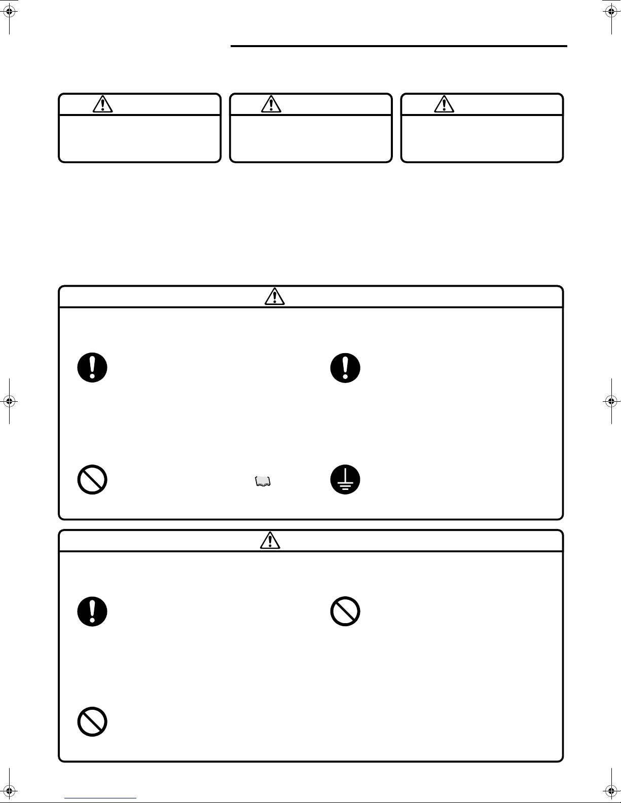
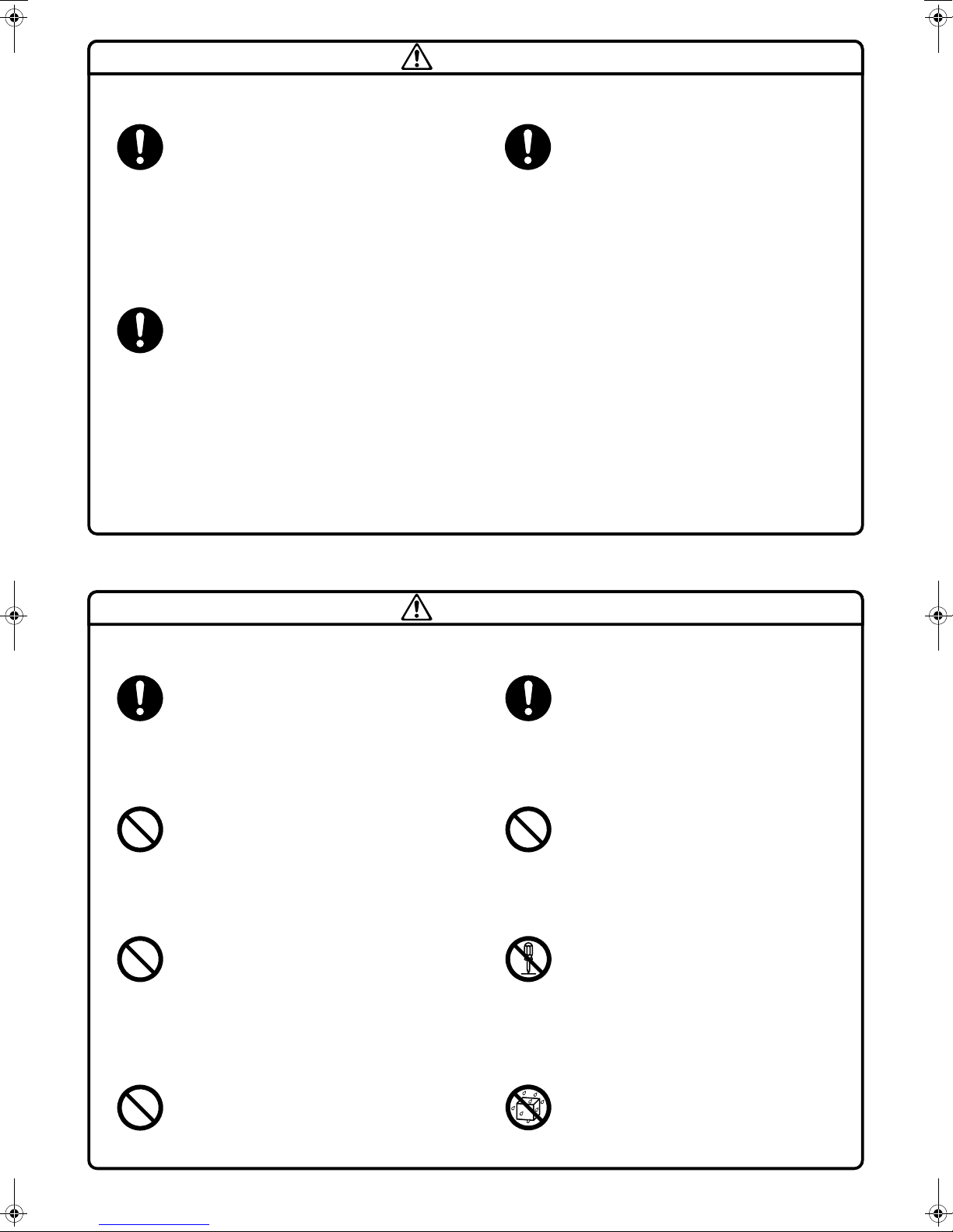
1SafetyPrecautions
OilCooling Unit and Accessories
4
Precautionsfor Installation 5
ElectricWiring 7
MonitorItems 23
TimerOperation 24
AdditionalSetting Functions 25
SettingAdditional Function 27
ForTemperatureControl Improvement 30
Alarm/WarningOutput Logic 33
AlarmSettings for Optional Protection
Devices(Installed by User) 33
Machinetemperature tuning control 34
36
37
Maintenance/Inspection
•Daily maintenance/inspection
•Periodic maintenance/inspection
•To leavethe unit unused for a long period
Troubleshooting
•When the unit operation seems abnormal
althoughno alarm is activated
•When an alarm is activated
Communicationwith main machine 35
PIM00132
Proper use results in power saving
Installation
Procedure
Before
Operation
Useful
Functions
Maintenance
Troubleshooting
Optional
Functions
Operating
Procedure
Installation
Models
Menu
Series
AKZJ188
AKZJ358
AKZJ458
AKZJ568
AKZJ908
Handling
Optional Parts
Maintenance
Immersion type
Instruction Manual
AKZJ8 Series
DAIKIN Oil Cooling Unit
(“OILCON”)
Built-inbreaker
model
Different-voltage
model
CEmodel
Built-inheater
model
Standard
model
Built-in
breaker
model(–B)
CEmodel
(–C)
Built-in
heater
model(–H)
Different-
voltage
model(–E)
Ifthe air filter is clogged, the cooling performance deteriorates,
causingexcess power consumption.
Cleanthe air filter periodically to reduce power consumption.
Thankyou for purchasing DAIKIN Oil Cooling Unit (“OILCON”).
Thisinstruction manual includes instructions for using the Oil
CoolingUnit.
Toensure proper use of this product, be sure to read through this
instructionmanual before using it.
Afterreading this manual, keep it handy for your future reference.
BeforeOperation
12ModelIdentification and Specifications
14
PartNames and Functions 15
Namesand Functions of the Control Panel Parts
16
CheckingInitial Operating Conditions 18
OperationSetting 19
Holdingconstant tank liquid temperature 20
Tuningtank liquid temperature to room
temperature(or machine temperature)
21
Coolingliquid in the tank at constant
capacity(%) 22
CONTENTS
1SafetyPrecautions
OilCooling Unit and Accessories
4
Precautionsfor Installation 5
ElectricWiring 7
MonitorItems 23
TimerOperation 24
AdditionalSetting Functions 25
SettingAdditional Function 27
ForTemperatureControl Improvement 30
Alarm/WarningOutput Logic 33
AlarmSettings for Optional Protection
Devices(Installed by User) 33
Machinetemperature tuning control 34
36
37
Maintenance/Inspection
•Daily maintenance/inspection
•Periodic maintenance/inspection
•To leavethe unit unused for a long period
Troubleshooting
•When the unit operation seems abnormal
althoughno alarm is activated
•When an alarm is activated
Communicationwith main machine 35
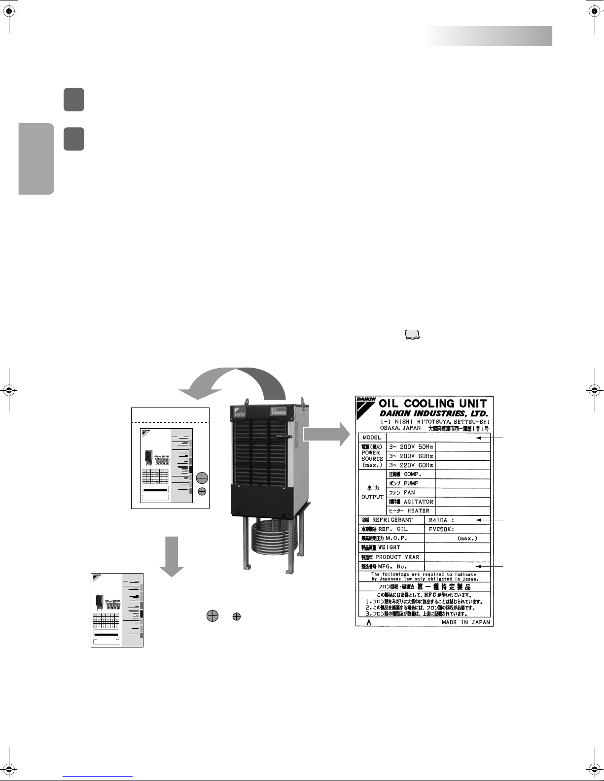
Oil Cooling Unit and Accessories
Check the following items:
Check the model name and serial No. (MFG. No.) on the nameplate attached to the right side of the Oil Cooling Unit.
Oil Cooling Unit
1
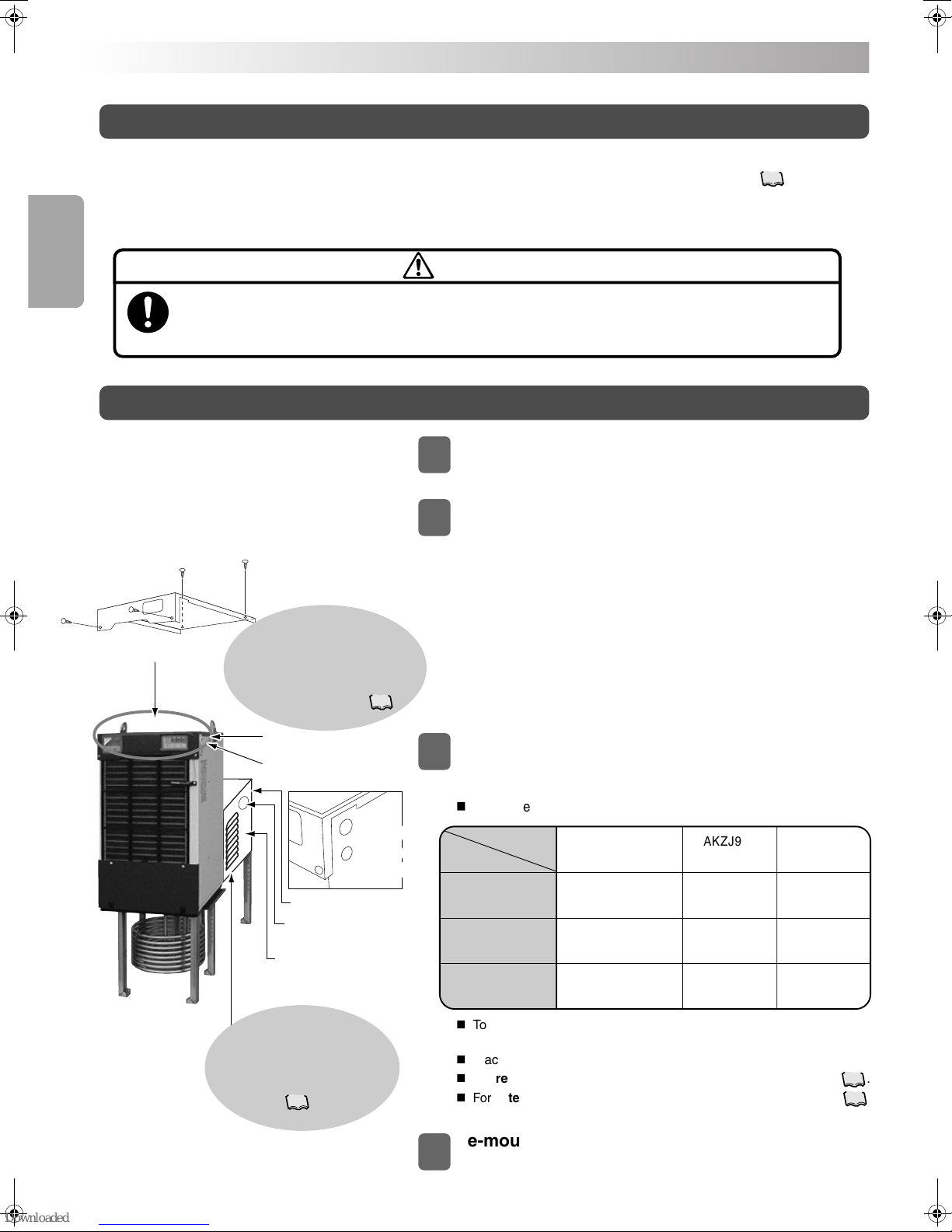
An accessory package∗1is attached to the top plate of the Oil Cooling Unit. Make sure that the following items are included
in the accessory package.
Accessories
2
+
Accessory package
Machine nameplate
Rubber bushing
(Large and small, 1 pc. each)
Model
name
Type of
refrigerant
Manufacture
No.
Oil Cooling Unit
1.
Instruction manual (This document): 1 volume
Keep this manual in place where users can read it whenever required.
2.
Rubber bushing for electric wiring (Large size, with cross slit): 1 pc.
When connecting the power cable, remove the resin cable hole cap in the side plate of the unit, and attach the rubber
bushing. It is only for provisional use.∗2
3.
Rubber bushing for electric wiring (Small size, with cross slit): 1 pc.
When connecting the signal cable, remove the resin cable hole cap in the side plate of the unit, and attach the rubber
bushing. It is only for provisional use.∗2
∗1: Before operation, be sure to remove the accessory package. Otherwise, the package blocks exhaust air flow, resulting in cooling
capacity deterioration.
∗2: When connecting each cable finally, place the cable in a conduit. If the rubber bushing is used, the dust-proof effect of the electrical
equipment box deteriorates, causing a fault. For details, refer to “Wiring procedure” on page .
8
Instruction manual
(This document)
PIM00132A_EN.fm 4 ページ 2007年9月20日 木曜日 午後3時4分