Daikin O-UC12-FEB23-3 Maintenance and service guide

O-UC12-FEB23-3
Low Temperature
Scan below QR code to download latest manual from
Website: https://drm.daikinmalaysia.com/download/
AIR COOLED
COMMERCIAL REFRIGERATION
SLIM UNIT COOLER
INSTALLATION, MAINTENANCE
IOM NO: O-UC12-FEB23-3

O-UC12-FEB23-3 Page I
IMPORTANT!
READ BEFORE THE PROCEEDING!
GENERAL SAFETY GUIDELINES
This guideline is intended for users to ensure safe installation,
operation, and maintenance of Daikin’s unit cooler. This
guideline is not intended to replace the system expertise
available from the system manufacturers.
This equipment when connected to the outdoor unit is a
relatively complicated apparatus. During installation,
operation, maintenance or service, individuals may be
exposed to certain components or conditions including, but not
limited to refrigerants, materials under pressure, rotating
components, and both high and low voltage. Each of these
items has the potential, if misused or handled improperly, to
cause bodily injury or death. It is the obligation and respon-
sibility of operating/service personnel to identify and
recognize these inherent hazards, protect themselves, and
proceed safely in completing their tasks. Failure to comply
with any of these requirements could result in serious damage
to the equipment and the property in which it is situated, as
well as severe personal injury or death to themselves and
people at the site.
This document is intended for use by owner-authorized
operating/service personnel. It is expected that these
individuals possess independent training that will enable them
to perform their assigned tasks properly and safely. It is
essential that, prior to performing any task on this equipment,
this individual shall have read and understood this document
and any referenced materials. This individual shall also be
familiar with and comply with all applicable governmental
standards and regulations pertaining to the task in question.
SAFETY SYMBOLS
The following symbols are used in this document to alert the
reader to specific situations:
WARNING
Warning! Risk of serious injury or death to
person!
CAUTION
Caution! Danger which can lead to serious
damages!
NOTICE
Notice! Risk of damage to equipment!
DISPOSAL
At the end of the system’s useful life, a suitably qualified
engineer or serviceman should decommission it. The
refrigerant and lubricant are classed as hazardous waste and
as such must be reclaimed and disposed of in the correct
manner. The system components to be disposed or recycled as
appropriate in the correct manner.
CHANGEABILITY OF THIS DOCUMENT
In complying with Daikin’ policy for continuous product
improvement, the information contained in this document is
subject to change without notice. Daikin makes no commitment
to update or provide current information automatically to the
manual owner. Updated manuals, if applicable, can be
obtained by contacting the nearest Daikin Service office.
Operating/service personnel maintain responsibility for the
applicability of these documents to the equipment. If there is
any question regarding the applicability of these documents,
the technician should verify whether the equipment has been
modified and if current literature is available from the owner
of the equipment prior to performing any work on the
equipment.
TABLE OF CONTENTS
NOMENCLATURE ............................................................... 1
PRODUCT FEATURES ..........................................................1
SPECIFICATION...................................................................2
GENERAL.............................................................................. 2
CAPACITY,R404A................................................................. 2
CAPACITY FACTOR.................................................................. 3
TD CORRECTION FACTOR ........................................................ 3
UNIT DIMENSION................................................................... 3
HEALTH AND SAFETY.......................................................... 1
INSTALLATION....................................................................1
UNIT LOCATION AND FIXING..................................................... 1
Figure 1: Minimum Wall Distance and Drain Trap ....... 2
FIELD PIPING......................................................................... 2
PRESSURE TESTING................................................................. 2
EVACUATION AND CHARGING................................................... 2
DRAINAGE............................................................................ 2
EXPANSION VALVE ................................................................. 3
ELECTRICAL........................................................................... 3
COMMISSIONING............................................................... 3
SERVICE AND MAINTENANCE............................................. 4
TABLE 1: TROUBLESHOOTING CHART ......................................... 4
WIRING DIAGRAM ................................................................. 2
LFSLHS0200AXV1 .......................................................... 2
LFSLHS0300AXV1 .......................................................... 2

O-UC12-FEB23-3 Page 1
Nomenclature
L
FS
LH
_
S
0200
A
_
X
V1
Power supply,
V1 –1ph/50Hz/220~240V;
Y1 –3ph/50Hz/380~415V
Special symbol.
Minor change revision.
Model change revision
Cooler nominal capacity in kW
0200 –2.0kW
Refrigerant:
P –R407C; Q –R410A; S –R404A
Special specification symbol, usually omitted
Function symbol
LN –Medium Temp. evaporator without heater;
LH –Low Temp. evaporator with heater
Unit Category:
FS- Indoor Slim Unit
Application Type:
L - Low temperature
Product Features
These evaporator DX units are designed for specific use in small cold rooms at negative temperature -28 oC to -13oC and it is
compatible with multiple refrigerants: R404A, R410A, R507A, R448A and R449A. The design of the unit enables the
maintenance access in ease.
•The coil is constructed from bare aluminum fins patterned V Wave with fins spacing 5mm, copper bare tubes with nominal
diameter of 10mm. This fins pattern stands out for better performance of air flow and heat transfer.
•Superheat measurement, air tightness test and vacuuming could be done easily via the provided shredder port 7/16-
20UNF which built into the suction header.
•Drain pan fitting ¾” BSP is supplied loose and must be fitted on site.
•Galvanized mild steel casing with polyester powder coating.
•Branded EBM single phase fan 230V/~/50Hz, 4 poles with protection class IP54. Low power consumption and integrate
thermal protection by thermos contacts which ensure reliable protection against thermal overload.
•An electrical defrost heater is included at the lower portion of the coil, eliminating the needs for the drain pan heater.
•All the wiring from the motor and heater is terminated at the electrical box mounted externally.
•This product is only suitable for fixed installation and the fan is blow through coil, which allows the coil to remove the fan
heat.

O-UC12-FEB23-3 Page 2
Specification
General
Model
LFSLHS0200AXV1
LFSLHS0300AXV1
Nominal Capacity
kW
2.0
3.0
Sound Pressure Level
dB(A)
60
60
General
Power supply
(V/Ph/Hz)
220-240/1/50
220-240/1/50
Size L/W/H (mm/mm/mm)
1381 x 510 x 238
1981 x 510 x 238
Weight (kg)
27.0
35.0
Room Temperature (oC)
-13 to -28
-13 to -28
Refrigerant
R404A/R410A/R507A/
R448A/R449A
R404A/R410A/R507A/
R448A/R449A
Max operating pressure (Bar)
25
25
Fan
Fan Size (mm x Qty)
300 x 2
300 x 3
Air Flow (m3/h)
1350
2025
Fan Speed (rpm)
1250
1250
Running current (A)
0.54
0.81
Power Consumptions (W)
70
105
Air Throw
Distance (m)
7
7
Heater
Power Consumptions (W)
1300
2000
Qty
1
1
Finishing
Casing
Galvanized & Powder Coated
Color
White
White
Connection Pipe Size
(OD)
Outlet (mm)
15.88
19.05
Inlet (mm)
12.7
12.7
*Nominal capacities are rated in accordance with EN 328, SC3 (wet coil condition) for R404A with TD = 7K.
* Sound Pressure Level is measured at 1m away from every side of the unit and 1m below fan center line, inside the anechoic
sound room.
* Air throw distance is declared based on a final air velocity of 0.4m/s.
Capacity, R404A
Refrigerant
Nominal Cooling Capacity, Qw for R404A (kW), TD =7K
Te
Model
-35
-30
-25
-20
LFSLHS0200AXV1
1.57
1.74
2.0
2.4
LFSLHS0300AXV1
2.34
2.67
3.0
3.33
TD = Air inlet temperature - Evaporating temperature at the outlet (Te)
Above table nominal capacities refer to wet coil cooling capacity, Qw
According to EN 328 standard condition refer dry coil condition denoted with Qstd
Standard
Condition
Air Inlet Temperature, tA1
(0C)
Evaporating Temperature
(dew point), Te (0C)
Relative Humidity Air
Inlet, %
Wet Coil
Factor
SC2
0
-8
85
1.15
SC3
-18
-25
95
1.05
Example: Model: LFSLHS0200AXV1 and Te -250C
Dry coil capacity, Qstd = Qw/wet coil factor = 2.0/1.05 = 1.90kW

O-UC12-FEB23-3 Page 3
Capacity Factor
To calculate cooling capacity of different refrigerants, multiply the cooling capacity for R404A with the respective capacity
factory.
Refrigerant
Model
R404A
R410A
R507A
R448A
R449A
LFSLHS0200AXV1
1
1.1
0.95
1
1
LFSLHS0300AXV1
1
1.1
0.95
1
1
TD Correction Factor
To calculate cooling capacity for different temperature difference, multiply the cooling capacity obtained from section 2.2.2
with respective TD correction factor.
TD(K)
4.5
5
5.5
6
6.5
7
7.5
8
8.5
9
9.5
Correction
Factor
0.64
0.71
0.79
0.86
0.93
1
1.07
1.14
1.21
1.29
1.36
Unit Dimension
Model
L (mm)
FL (mm)
W (mm)
H (mm)
LFSLHS0200AXV1
1381
1313
510
238
LFSLHS0300AXV1
1981
1913
510
238

O-UC12-FEB23-3 Page 1
Health and Safety
Only a qualified refrigeration
engineer/technician, who is familiar with
refrigeration systems and components
including all controls, should perform the
installation and start-up of the system. To avoid potential
injury, use care when working around coil surfaces or
sharp edges of metal cabinets. All piping and electrical
wiring should be installed in accordance with all
applicable codes, ordinances, and local by-laws.
Before Installation
•Ensure the units received are the correct models for the
intended application.
•If the holding charge (4 bars ± 1bar nitrogen) is not
present, do not use the product and contact the sales
representative immediately. (Manufacturer’s warranty is
void for damage caused by incorrect application or unit
mishandling).
•The holding charge should be safely released through
the schrader port on the suction header.
•Check there is no damage to the units (piping not dented,
fan motor’s electrical box with no sign of cracks). Any
damage should be reported to the supplier immediately.
•Check to ensure tightness for the wiring and the fan.
•Check that the proposed equipment locations are suitable
and provide adequate support for the weight of the units.
Offloading and Lifting
•Whenever handling a unit with packaging, it should be
from the base (refer the marking on the carton box) and,
where possible, all packing and protection is kept in
position.
•When offloading the unpacked unit on the ground, the
drain pan shall face upwards to avoid denting the drain
pan (slope).
•Lift the unit from two ends for installation. If a lifting
instrument is used, ensure cushion is used to protect the
unit casing from damage.
•Do not drop the unit. Should this inadvertently happen, it
should be immediately inspected for damage.
During Installation and subsequent maintenance
•Installation and maintenance are to be performed only
by qualified personnel who are familiar with local codes
and regulations and experienced with this type of
equipment.
•Safe working methods are identified, and operatives
have suitable PPE.
•Ensure the working area has adequate ventilation during
brazing procedures.
•The units contain moving machinery and electrical power
hazards, which may cause severe injury or death.
Disconnect and shut off power before installation or
service of the equipment.
•Refrigerant release into the atmosphere is illegal. Proper
evacuation, recovery, handling, and leak testing
procedures must always be observed.
•Units must be grounded to the screw terminal labelled
•No maintenance work should be attempted prior to
disconnecting the electrical supply.
•The electrical covers and fan guards must remain always
fitted.
•Use of the units outside of the design conditions and the
application for which the units were intended may be
unsafe and be detrimental to the units, regardless of
short- or long-term operation.
•The units are not designed to withstand loads or stress
from other equipment or personnel. Such extraneous
loads or stress may cause failure/leak/injury.
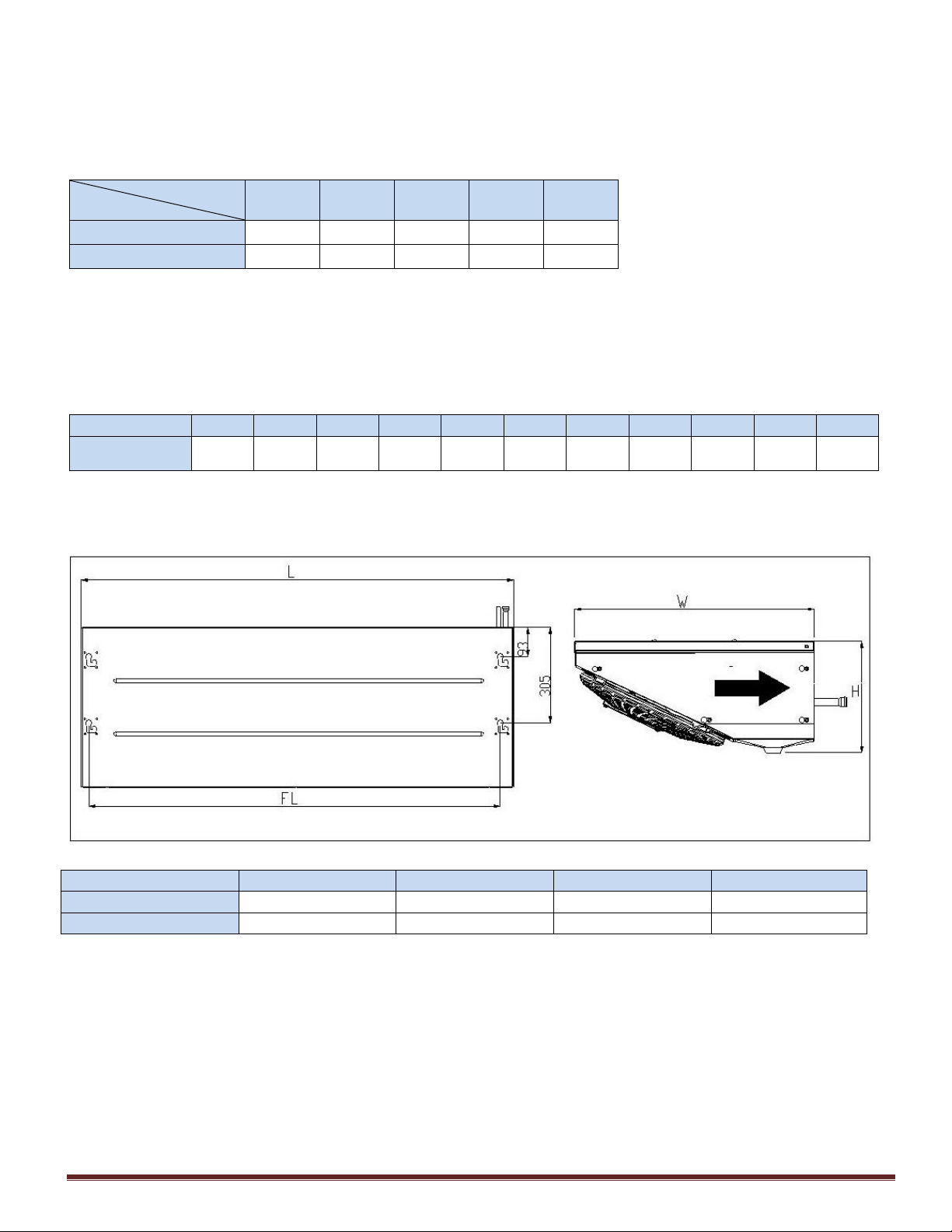
Installation
Unit location and Fixing
•All indoor units must be level in all directions, to ensure
water condensation can be properly drained out.
•The indoor units can be mounted directly to the ceiling
utilizing the fixing holes on the top of the unit. No
additional brackets are required.
•Position the indoor unit where the optimum airflow can be
achieved. Avoid locating in corners or in alcoves which
may restrict airflows. For best performance, it is
desirable to arrange the air blowing toward the door to
minimize the entrance of warm moist air when door is
open. Light fixtures, shelving and product boxes must be
arranged in such that it does not block the air intake and
air discharge from the unit cooler.
•A minimum 10mm raw bolt type fixing is required with a
large steel washer to bear the indoor unit weight. It is
important to ensure that the wall/ceiling can withstand
the unit weight and that all fixings are secure.
•The installation location should allow sufficient space for
air flow and maintenance around the units:
•The fan face must be located a minimum of 600mm (H)
from walls to assure unrestricted air intake.
•Ensure that the ceiling can withstand the unit weight
and that all fixings are secure.

O-UC12-FEB23-3 Page 2
Figure 1: Minimum Wall Distance and Drain Trap
Field piping
Use of incorrect pipe sizes affects the system’s
oil return and pressure drops. Refer
information given on Page 3. All local codes of
practice must be observed in the installation of
refrigerant piping.
To ensure satisfactory operation and performance, the
following points should be noted for field piping
arrangements:
•Pipework routes must be as simple and as short as
possible.
•Use of incorrect pipe sizes can affect system
pressures/temperatures and gas velocity for proper oil
return.
•Avoid low points on pipework where oil can accumulate.
•Use only clean, dehydrated refrigeration grade copper
tube with long radius bends.
•When brazing use only silver alloy rods.
•Run braze without over filling to ensure there is no
leakage into the tube.
•To prevent oxidization, blow oxygen free nitrogen
through pipework when brazing.
•Protect the casing of the unit when brazing connections.
•Install insulation with a minimum wall thickness of 3/8” on
suction lines to prevent sweating and ensure only
superheated vapor is returned to compressor suction.
•Adequately support all pipe work at a maximum of 2-
meter intervals.
Pressure testing
•The unit cooler has been pressure tested in the factory
prior to dispatch. The indoor unit contains a holding
charge of oxygen free nitrogen.
•Once the pipework installation is complete, it should be
pressure tested prior to evacuation to test for leaks.
•A pressure leak test should be carried out using oxygen
free nitrogen (OFN). NEVER USE OXYGEN FOR
PRESSURE TESTING SYSTEMS. A calibrated nitrogen
pressure regulator must always be used. Before starting
any pressure testing, ensure the area surrounding the
system is safe, inform relevant personnel and fit warning
signs indicating high pressure testing. Also, use correct
PPE as required.
A simple procedure for testing as follows:
•Connect a pressure hose from the regulator to the
schrader connection on the service port of the unit.
•Pressure system slowly up to 3 bar (45 psi) for 5 minutes
and check for any signs of leakage.
•Increase pressure slowly up to 10 bar (150 psi) for 5
minutes and check for any signs of leakage.
•Increase pressure slowly up to 20 bar (300 psi) and
check for any signs of leakage. Leave system under
pressure for 24 hours.

O-UC12-FEB23-3 Page 2
•Listen for any possible leaks and check all joints with
bubble spray. If any leaks are discovered, release
pressure slowly from system until empty, repair leak and
then restart pressure testing procedure. Never attempt to
repair a leak on a pressurized system.
A strength test should also be incorporated according to local
regulations.
Once testing has been completed satisfactorily, release the
pressure from the system gradually and safely to external
atmosphere.
Evacuation and Charging
Moisture prevents proper functioning of the
compressor and the refrigeration system.
Ensure that a good quality vacuum pump is
used to pull a minimum vacuum of 250
microns (0.25 torr).
Once pressure testing has been completed, the system can
now be evacuated to remove air and any moisture from the
piping. This can be done as follows:
•Ensure any nitrogen charge is safely released from the
system.
•Connect a gauge manifold to the schrader connection of
the unit.
•Connect a vacuum pump and vacuum gauge to the
system.
•Evacuate the system until vacuum is below 250 microns
(0.25 torr).
Note: A triple evacuation procedure is recommended for all
new systems or where moisture is suspected.
Once the system is isolated and the vacuum pump is switched
off, any rise in pressure indicates that either there may be a
leak in the system or moisture is still present. In this case,
recheck the system for leaks, repair as necessary, and then
restart the evacuation procedure. Once completed
satisfactorily, the vacuum pump and vacuum gauge can be
removed.
Drainage
The evaporator drain pan fitting is supplied
loose and must be fitted on site.
Correct fitting is vital to ensure leak –free operation. The
lock nut on the drain fitting MUST be fitted the right way
around; otherwise, it will not tighten against the drip tray.
One side of the nut has an angled recess –this must be facing
towards the drip tray. The fitting does not require any
sealant, but a small amount of silicon sealant can be applied
between the flared face of the fitting and the drip tray if so
desired.
The fitting is tied to the indoor unit’s fan guard and consists of:
•1pcs aluminum alloy drain fitting 3/4” BSP male thread
and
•1pcs hexagon locknut.
To install the drain fitting, firstly unscrew the drain pan from
the indoor unit. Locate the drain fitting into drain pan,
followed with locknut to secure the drain fitting to the drain
pan. Then refit the drain pan to the unit. Follow diagram
below to install the drain fitting in the correct way.
The locknut only requires hand tightening and then pinching
up with a spanner. Do not over tighten, else the threads may
strip from the nut and damage the tray.
Recommended minimum drainpipe diameter is 20mm or 3/4”.
The drainpipe material could be either copper or plastic. It is
not recommended to use flexible hose as it tends to kink
easily which might cause blockage and water to back up in
the unit.
Drainpipe must be leveled to permit free draining of
condensate from unit cooler.
Drain traps need to be installed for trouble free operation.
If the unit cooler is operated without the drain trap, warm
air with higher temperature will draw from outside to the
cold room. Thus, warm air will significantly reduce the cooler
capacity and may lead to ice formation in the drain pan.
If the temperature surrounding the drain line and trap is
below freezing (0oC), it must be wrapped with a drain line
heater. Drain pan coupling and drainpipe must be insulated
up to the external wall surface of the cool room. Make sure
the drain pan and drain line is free from debris to avoid
clogging and cause overflowing.

O-UC12-FEB23-3 Page 3
Expansion Valve
•Expansion valve is not pre-fitted into all unit models.
•External pressure equalization type thermostatic
expansion valve needs to be used with this type of unit
cooler to compensate pressure drop through the
evaporator and distributors.
•For one outdoor to one indoor system low temperature
application, a maximum operating pressure (MOP) type
expansion valve must be used to limit the suction
pressure rise to a maximum of 4 bar relative (-50C).
Higher suction pressure than compressor working
envelope might cause compressor overload. Do not
apply both suction pressure regulator and MOP-type
expansion valve in combination with one another.
•When required, access to the adjusting screw of
expansion valve to alter the suction superheat. To avoid
liquid back to compressor, it is recommended suction
superheat 10K to 20 K for normal operating condition.
Electrical
•The mains electrical supply to the indoor unit must be
via a suitably rated isolator and motor rated circuit
breaker or fuse.
•Check electrical safety (leakage current, withstand
voltage, earth continuity) after connected to heaters,
fuse, and timers.
•Thermal fuse must be supplied by site to protect the
defrost heater from overheating.
Daikin Slim Unit Cooler require a 230 volt / 1 phase / 50Hz
supply which must include Earthing. They are not suitable for
any other supply voltages (other than a deviation of +/- 10%
of the above values) and are not suitable for 60 Hz supplies.
Units must be earthed, and no maintenance work should be
attempted prior to disconnecting the electrical supply.
Installation of earth wire should be made to earth screw
before connecting the live wires. The earth wire shall be
slacked with longer length as shown in below diagram.
•Cable type and sizing must be selected for the
application and the electrical installation should conform
to the current local standards. The power cable to the
indoor unit should be 3 core (2 core + E).
•Cables to the indoor unit should be routed through the
bush wires of the electrical metal enclosure.
•Removal of the metal cover plate gives access to the
terminal blocks for the fan and heater. The wiring
diagram could be found at the inner side of the metal
cover plate.
•A defrost heater is pre-inserted at the bottom of the coil.
To protect the heater from overheating, it is important to
install a thermal fuse (to be supplied by site) in the
heater circuit. The thermal fuse should be appropriately
located to cut off safely when the heater is overheated.
Commissioning
Before starting the system, ensure that all
electrical connections are correctly made and
tight, and all covers and guards are fitted.
After the installation is completed, a review of the
following items should be performed before the
system is placed into operation:
Check electrical connections, fan motors, fan guard and
all other fasteners for tightness. Ensure the thermostatic
expansion valve bulb is properly located, strapped,
and insulated.
With the system operating, check the supply voltage. It
must be within +/- 10% of the voltage marked on the unit
nameplate.
Be alert that during defrosting, the surrounding
temperature of the unit may rise dramatically.
Kindly keep a safe distance from the unit.
A defrost cycle is needed when the frost build up is such
that it impedes the airflow through the coil. The defrost
settings is vary for each installation and may need to be
changed depending on the time of the year and other
conditions.
Check the drain line and make sure drain line is clear and
unit is aligned in all position to avoid overflow of
condensation water.
Heater
Location

O-UC12-FEB23-3 Page 4
Service and Maintenance
A preventative maintenance schedule should be set up as
soon as the Unit Cooler is installed. The unit should be
inspected periodically for proper operation and buildup
of dirt.
1. Inspect and clean the drain pan to ensure there is
no blockage. The drain pan should be cleaned
regularly with warm water and neutral detergent.
2. The cabinet can be cleaned with water and neutral
detergent. DO NOT clean the fans and fins using a water
jet or high-pressure cleaner.
3. The evaporator coil should be checked once a month for
proper defrosting. Many variables
affect coil
frosting
such as room temperature, type of product being stored,
how often new product is brought in and the length of
time the door to the room remains open. Summer
conditions of high humidity can cause heavier frost loads.
It may be necessary to change the numbers of defrost
cycles seasonally.
4. At least every six months check all fan motors. Tighten
motor mounting screws and fan set screws.
Table 1: Troubleshooting Chart
PROBLEM
POSSIBLE CAUSES
CORRECTIVE ACTION
Excessive buildup of
frost on coil.
•Defrost time is too short.
•Extend defrost period on the
temperature controller.
•Too high humidity in room.
•Limit access to cold room; do not keep
doors open during stocking.
Accumulation of ice or
water in drain pan.
•Drain line plugged.
•Clean drain line. Make sure drain line is
insulated properly.
•Drainpipe does not have slope angle.
•Install the drain line with slope.
•Indoor unit does not install in level at all
directions.
•Check unit installation and align the unit
level at all directions.
•Drain line does not have drain trap.
•Install drain line trap.
Noise
•· Resonance on the vibrating
mounting parts.
•Fix the position of vibrating part
correctly.
•Vibration of fan or fan mounting
misaligned.
•Fix the position of fan correctly; replace
if defective.
Room temperature too
high (not cold)
•Incorrect setting on the temperature
controller.
•Correct the temperature controller
setting.
•The compressor stopped by alarms
triggered on the controller.
•Check the type of error, fix the error
and replace the defective parts if any.
•Incorrect sensor temperature.
•Check the room temperature sensor
location. Ensure it was not affected by
other sources.
•Insufficient refrigerant flow to
evaporator.
•Check for any refrigerant leakage or
choking on expansion valve. Repair the
fault and charge system if necessary.
•Thick frost built on evaporator coil.
•Defrost the coil and clean the frost.
•Too frequent defrosting.
•Reduce defrost cycle frequency.
•Incorrect matching of indoor capacity to
outdoor.
•Review and reselect the unit
combination.

O-UC12-FEB23-3 Page 2
Wiring Diagram
LFSLHS0200AXV1
LFSLHS0300AXV1

O-UC12-FEB23-3
RJ0110030009448
DAIKIN REFRIGERATION MALAYSIA SDN. BHD. (34543-W)
Shah Alam Plant: 11A, Jalan Utas 15/7, Seksyen 15, 40200 Shah Alam, Selangor, Malaysia.
Banting Plant: Lot 10, Jalan Perusahaan 8, Kawasan Perusahaan Pekan Banting, 42700 Banting, Selangor, Malaysia.
Tel: 603-3187 2911 Fax: 603-3187 8597
Table of contents
Other Daikin Freezer manuals