Daikin EKSR3PA User manual

Control and pump unit
for solar systems
Control and pump unit for solar systems
Operating and installation instructions English
EKSR3PA
EKSRDS1A
Operating and installation instructions


Contents
EKSR3PA + EKSRDS1A
Control and pump unit for solar systems
4PW56033-1
Operating and installation instructions
3
1 Safety . . . . . . . . . . . . . . . . . . . . . . . . . . . . . . . . . . . . . . . . . . . . . . . . . . . . . . . . . . . . . . . . . . . . . . . . . . . . . . . . . . . 5
1.1 Observing Instructions. . . . . . . . . . . . . . . . . . . . . . . . . . . . . . . . . . . . . . . . . . . . . . . . . . . . . . . . . . . . . . . . . . . . . . . . . . . . . . . . . . . . 5
1.2 Warning signs and explanation of symbols. . . . . . . . . . . . . . . . . . . . . . . . . . . . . . . . . . . . . . . . . . . . . . . . . . . . . . . . . . . . . . . . . . . . . 5
1.3 Avoid danger . . . . . . . . . . . . . . . . . . . . . . . . . . . . . . . . . . . . . . . . . . . . . . . . . . . . . . . . . . . . . . . . . . . . . . . . . . . . . . . . . . . . . . . . . . . 6
1.4 Proper use. . . . . . . . . . . . . . . . . . . . . . . . . . . . . . . . . . . . . . . . . . . . . . . . . . . . . . . . . . . . . . . . . . . . . . . . . . . . . . . . . . . . . . . . . . . . . 6
1.5 Instructions for operating safety . . . . . . . . . . . . . . . . . . . . . . . . . . . . . . . . . . . . . . . . . . . . . . . . . . . . . . . . . . . . . . . . . . . . . . . . . . . . 6
2 Product description. . . . . . . . . . . . . . . . . . . . . . . . . . . . . . . . . . . . . . . . . . . . . . . . . . . . . . . . . . . . . . . . . . . . . . . . . 7
2.1 Design and components of the solar system . . . . . . . . . . . . . . . . . . . . . . . . . . . . . . . . . . . . . . . . . . . . . . . . . . . . . . . . . . . . . . . . . . . 7
2.2 Brief description . . . . . . . . . . . . . . . . . . . . . . . . . . . . . . . . . . . . . . . . . . . . . . . . . . . . . . . . . . . . . . . . . . . . . . . . . . . . . . . . . . . . . . . . 8
2.3 System components . . . . . . . . . . . . . . . . . . . . . . . . . . . . . . . . . . . . . . . . . . . . . . . . . . . . . . . . . . . . . . . . . . . . . . . . . . . . . . . . . . . . . 8
2.4 Accessories. . . . . . . . . . . . . . . . . . . . . . . . . . . . . . . . . . . . . . . . . . . . . . . . . . . . . . . . . . . . . . . . . . . . . . . . . . . . . . . . . . . . . . . . . . . . 9
3 Installation . . . . . . . . . . . . . . . . . . . . . . . . . . . . . . . . . . . . . . . . . . . . . . . . . . . . . . . . . . . . . . . . . . . . . . . . . . . . . . 10
3.1 System concepts. . . . . . . . . . . . . . . . . . . . . . . . . . . . . . . . . . . . . . . . . . . . . . . . . . . . . . . . . . . . . . . . . . . . . . . . . . . . . . . . . . . . . . . 10
3.1.1 Parallel connection . . . . . . . . . . . . . . . . . . . . . . . . . . . . . . . . . . . . . . . . . . . . . . . . . . . . . . . . . . . . . . . . . . . . . . . . . . . . . . . . . . 10
3.1.2 Serial connection . . . . . . . . . . . . . . . . . . . . . . . . . . . . . . . . . . . . . . . . . . . . . . . . . . . . . . . . . . . . . . . . . . . . . . . . . . . . . . . . . . . 10
3.2 Preparatory installation work . . . . . . . . . . . . . . . . . . . . . . . . . . . . . . . . . . . . . . . . . . . . . . . . . . . . . . . . . . . . . . . . . . . . . . . . . . . . . 10
3.3 Pump unit EKSRDS1A . . . . . . . . . . . . . . . . . . . . . . . . . . . . . . . . . . . . . . . . . . . . . . . . . . . . . . . . . . . . . . . . . . . . . . . . . . . . . . . . . . . 11
3.4 Controller EKSR3PA . . . . . . . . . . . . . . . . . . . . . . . . . . . . . . . . . . . . . . . . . . . . . . . . . . . . . . . . . . . . . . . . . . . . . . . . . . . . . . . . . . . . 12
3.4.1 Wall mounting. . . . . . . . . . . . . . . . . . . . . . . . . . . . . . . . . . . . . . . . . . . . . . . . . . . . . . . . . . . . . . . . . . . . . . . . . . . . . . . . . . . . . . 12
3.4.2 Electrical connections . . . . . . . . . . . . . . . . . . . . . . . . . . . . . . . . . . . . . . . . . . . . . . . . . . . . . . . . . . . . . . . . . . . . . . . . . . . . . . . . 13
3.5 Pump unit EKSRDS1A - electrical connection. . . . . . . . . . . . . . . . . . . . . . . . . . . . . . . . . . . . . . . . . . . . . . . . . . . . . . . . . . . . . . . . . . 15
3.6 Storage temperature sensor . . . . . . . . . . . . . . . . . . . . . . . . . . . . . . . . . . . . . . . . . . . . . . . . . . . . . . . . . . . . . . . . . . . . . . . . . . . . . . 15
3.7 FlowSensor (optional) . . . . . . . . . . . . . . . . . . . . . . . . . . . . . . . . . . . . . . . . . . . . . . . . . . . . . . . . . . . . . . . . . . . . . . . . . . . . . . . . . . . 16
4 Start-up and taking out of service . . . . . . . . . . . . . . . . . . . . . . . . . . . . . . . . . . . . . . . . . . . . . . . . . . . . . . . . . . . . 17
4.1 Initial start-up . . . . . . . . . . . . . . . . . . . . . . . . . . . . . . . . . . . . . . . . . . . . . . . . . . . . . . . . . . . . . . . . . . . . . . . . . . . . . . . . . . . . . . . . . 17
4.1.1 Filling solar panel circuit . . . . . . . . . . . . . . . . . . . . . . . . . . . . . . . . . . . . . . . . . . . . . . . . . . . . . . . . . . . . . . . . . . . . . . . . . . . . . . 17
4.1.2 Regulate the flow rate on the solar panel circuit . . . . . . . . . . . . . . . . . . . . . . . . . . . . . . . . . . . . . . . . . . . . . . . . . . . . . . . . . . . . 19
4.1.3 Filling the storage tank and heating circuit . . . . . . . . . . . . . . . . . . . . . . . . . . . . . . . . . . . . . . . . . . . . . . . . . . . . . . . . . . . . . . . . 19
4.2 Taking out of service. . . . . . . . . . . . . . . . . . . . . . . . . . . . . . . . . . . . . . . . . . . . . . . . . . . . . . . . . . . . . . . . . . . . . . . . . . . . . . . . . . . . 20
4.2.1 Temporary shutdown . . . . . . . . . . . . . . . . . . . . . . . . . . . . . . . . . . . . . . . . . . . . . . . . . . . . . . . . . . . . . . . . . . . . . . . . . . . . . . . . 20
4.2.2 Final shutdown . . . . . . . . . . . . . . . . . . . . . . . . . . . . . . . . . . . . . . . . . . . . . . . . . . . . . . . . . . . . . . . . . . . . . . . . . . . . . . . . . . . . . 20

Contents
Operating and installation instructions
4
EKSR3PA + EKSRDS1A
Control and pump unit for solar systems
4PW56033-1
5 Operation. . . . . . . . . . . . . . . . . . . . . . . . . . . . . . . . . . . . . . . . . . . . . . . . . . . . . . . . . . . . . . . . . . . . . . . . . . . . . . . . 21
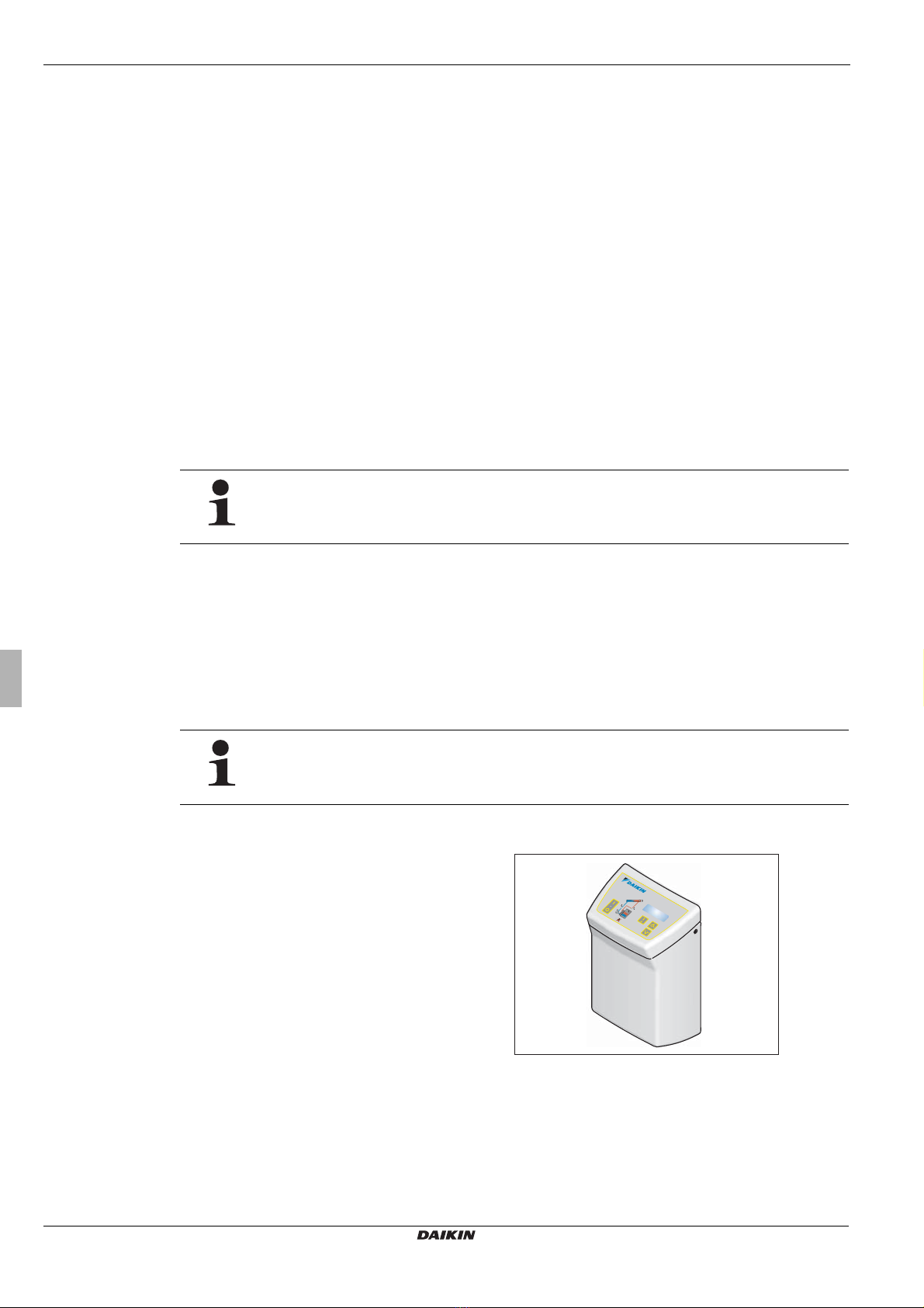
5.1 Operating and display components . . . . . . . . . . . . . . . . . . . . . . . . . . . . . . . . . . . . . . . . . . . . . . . . . . . . . . . . . . . . . . . . . . . . . . . . . . 21
5.2 Operation of control systems . . . . . . . . . . . . . . . . . . . . . . . . . . . . . . . . . . . . . . . . . . . . . . . . . . . . . . . . . . . . . . . . . . . . . . . . . . . . . . 21
5.2.1 Pump operation . . . . . . . . . . . . . . . . . . . . . . . . . . . . . . . . . . . . . . . . . . . . . . . . . . . . . . . . . . . . . . . . . . . . . . . . . . . . . . . . . . . . . 21
5.2.2 Contact for Solar Priority (BSK) . . . . . . . . . . . . . . . . . . . . . . . . . . . . . . . . . . . . . . . . . . . . . . . . . . . . . . . . . . . . . . . . . . . . . . . . . 23
5.2.3 Switch-on lock-out function . . . . . . . . . . . . . . . . . . . . . . . . . . . . . . . . . . . . . . . . . . . . . . . . . . . . . . . . . . . . . . . . . . . . . . . . . . . . 23
5.2.4 Manual operation. . . . . . . . . . . . . . . . . . . . . . . . . . . . . . . . . . . . . . . . . . . . . . . . . . . . . . . . . . . . . . . . . . . . . . . . . . . . . . . . . . . . 23
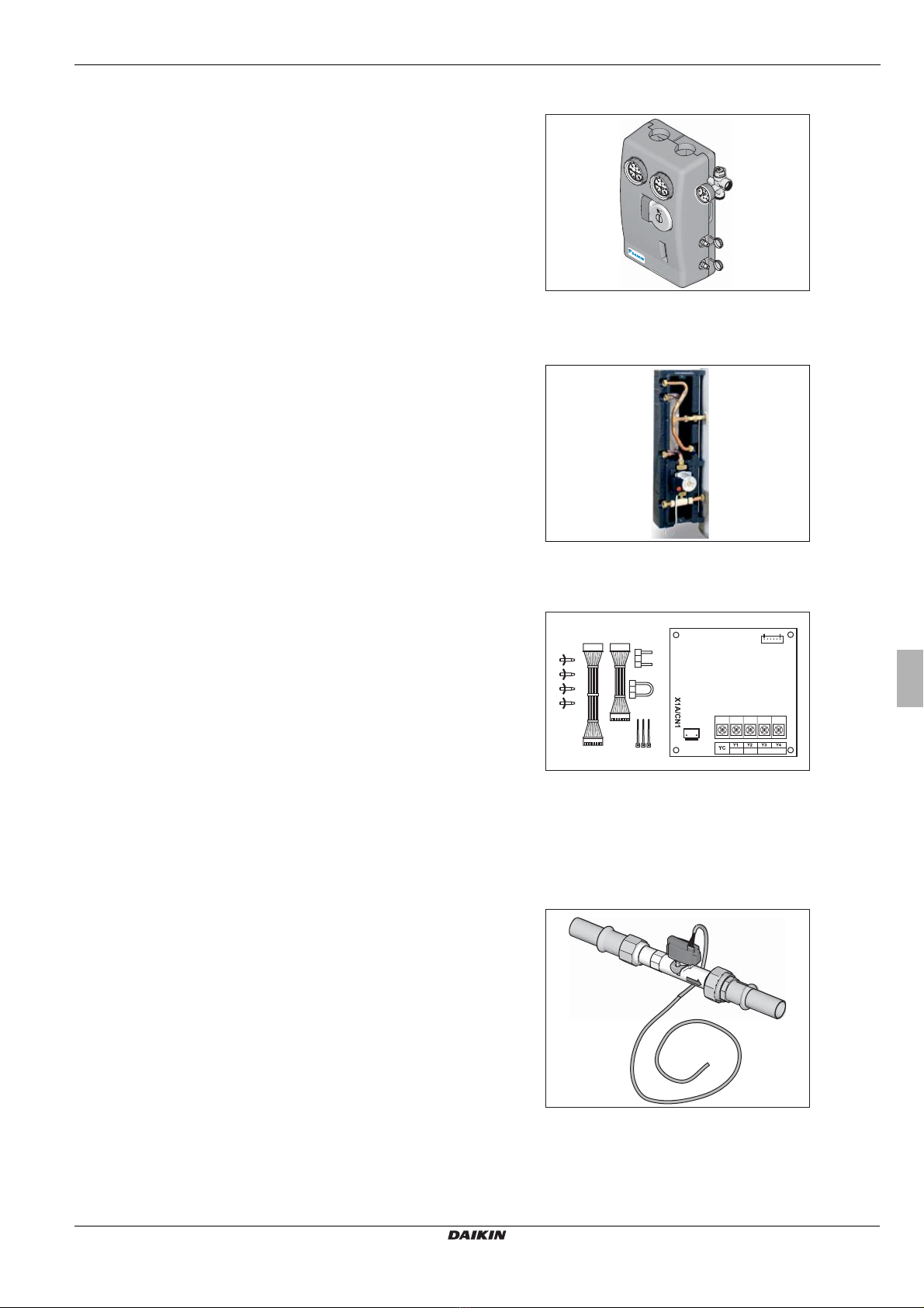
5.2.5 Solar FlowSensor EKSFLP12A . . . . . . . . . . . . . . . . . . . . . . . . . . . . . . . . . . . . . . . . . . . . . . . . . . . . . . . . . . . . . . . . . . . . . . . . . . 23
5.2.6 Output calculation, maximum values and yield count . . . . . . . . . . . . . . . . . . . . . . . . . . . . . . . . . . . . . . . . . . . . . . . . . . . . . . . . . 24
5.2.7 Speed regulation of the solar circuit pump PS . . . . . . . . . . . . . . . . . . . . . . . . . . . . . . . . . . . . . . . . . . . . . . . . . . . . . . . . . . . . . . 24
5.2.8 Global reset function . . . . . . . . . . . . . . . . . . . . . . . . . . . . . . . . . . . . . . . . . . . . . . . . . . . . . . . . . . . . . . . . . . . . . . . . . . . . . . . . . 26
5.2.9 Frost protection function . . . . . . . . . . . . . . . . . . . . . . . . . . . . . . . . . . . . . . . . . . . . . . . . . . . . . . . . . . . . . . . . . . . . . . . . . . . . . . 26
5.2.10 Leak protection function . . . . . . . . . . . . . . . . . . . . . . . . . . . . . . . . . . . . . . . . . . . . . . . . . . . . . . . . . . . . . . . . . . . . . . . . . . . . . . 26
5.3 Setting and menu operation . . . . . . . . . . . . . . . . . . . . . . . . . . . . . . . . . . . . . . . . . . . . . . . . . . . . . . . . . . . . . . . . . . . . . . . . . . . . . . . 27
5.3.1 Start display . . . . . . . . . . . . . . . . . . . . . . . . . . . . . . . . . . . . . . . . . . . . . . . . . . . . . . . . . . . . . . . . . . . . . . . . . . . . . . . . . . . . . . . 27
5.3.2 Operating display. . . . . . . . . . . . . . . . . . . . . . . . . . . . . . . . . . . . . . . . . . . . . . . . . . . . . . . . . . . . . . . . . . . . . . . . . . . . . . . . . . . . 28
5.3.3 Settings menu . . . . . . . . . . . . . . . . . . . . . . . . . . . . . . . . . . . . . . . . . . . . . . . . . . . . . . . . . . . . . . . . . . . . . . . . . . . . . . . . . . . . . . 28
5.3.4 Password input . . . . . . . . . . . . . . . . . . . . . . . . . . . . . . . . . . . . . . . . . . . . . . . . . . . . . . . . . . . . . . . . . . . . . . . . . . . . . . . . . . . . . 30
5.3.5 Language selection . . . . . . . . . . . . . . . . . . . . . . . . . . . . . . . . . . . . . . . . . . . . . . . . . . . . . . . . . . . . . . . . . . . . . . . . . . . . . . . . . . 30
5.3.6 Setting and resetting parameters . . . . . . . . . . . . . . . . . . . . . . . . . . . . . . . . . . . . . . . . . . . . . . . . . . . . . . . . . . . . . . . . . . . . . . . . 30
5.3.7 Manual setting of the pump speed regulation (only with connected FlowSensor EKSFLP12A). . . . . . . . . . . . . . . . . . . . . . . . . . . 30
5.3.8 Correction values for measuring points. . . . . . . . . . . . . . . . . . . . . . . . . . . . . . . . . . . . . . . . . . . . . . . . . . . . . . . . . . . . . . . . . . . . 31
5.4 Recommended settings. . . . . . . . . . . . . . . . . . . . . . . . . . . . . . . . . . . . . . . . . . . . . . . . . . . . . . . . . . . . . . . . . . . . . . . . . . . . . . . . . . . 31
5.4.1 Standard parameter settings, recommended setting ranges . . . . . . . . . . . . . . . . . . . . . . . . . . . . . . . . . . . . . . . . . . . . . . . . . . . . 31
5.4.2 Additional settings for your solar system . . . . . . . . . . . . . . . . . . . . . . . . . . . . . . . . . . . . . . . . . . . . . . . . . . . . . . . . . . . . . . . . . . 33
5.4.3 Domestic water hygiene. . . . . . . . . . . . . . . . . . . . . . . . . . . . . . . . . . . . . . . . . . . . . . . . . . . . . . . . . . . . . . . . . . . . . . . . . . . . . . . 33
6 Faults and malfunctions. . . . . . . . . . . . . . . . . . . . . . . . . . . . . . . . . . . . . . . . . . . . . . . . . . . . . . . . . . . . . . . . . . . . 34
6.1 Event display . . . . . . . . . . . . . . . . . . . . . . . . . . . . . . . . . . . . . . . . . . . . . . . . . . . . . . . . . . . . . . . . . . . . . . . . . . . . . . . . . . . . . . . . . . 34
6.2 Troubleshooting . . . . . . . . . . . . . . . . . . . . . . . . . . . . . . . . . . . . . . . . . . . . . . . . . . . . . . . . . . . . . . . . . . . . . . . . . . . . . . . . . . . . . . . . 35
7 Technical data. . . . . . . . . . . . . . . . . . . . . . . . . . . . . . . . . . . . . . . . . . . . . . . . . . . . . . . . . . . . . . . . . . . . . . . . . . . . 37
7.1 Basic data . . . . . . . . . . . . . . . . . . . . . . . . . . . . . . . . . . . . . . . . . . . . . . . . . . . . . . . . . . . . . . . . . . . . . . . . . . . . . . . . . . . . . . . . . . . . 37
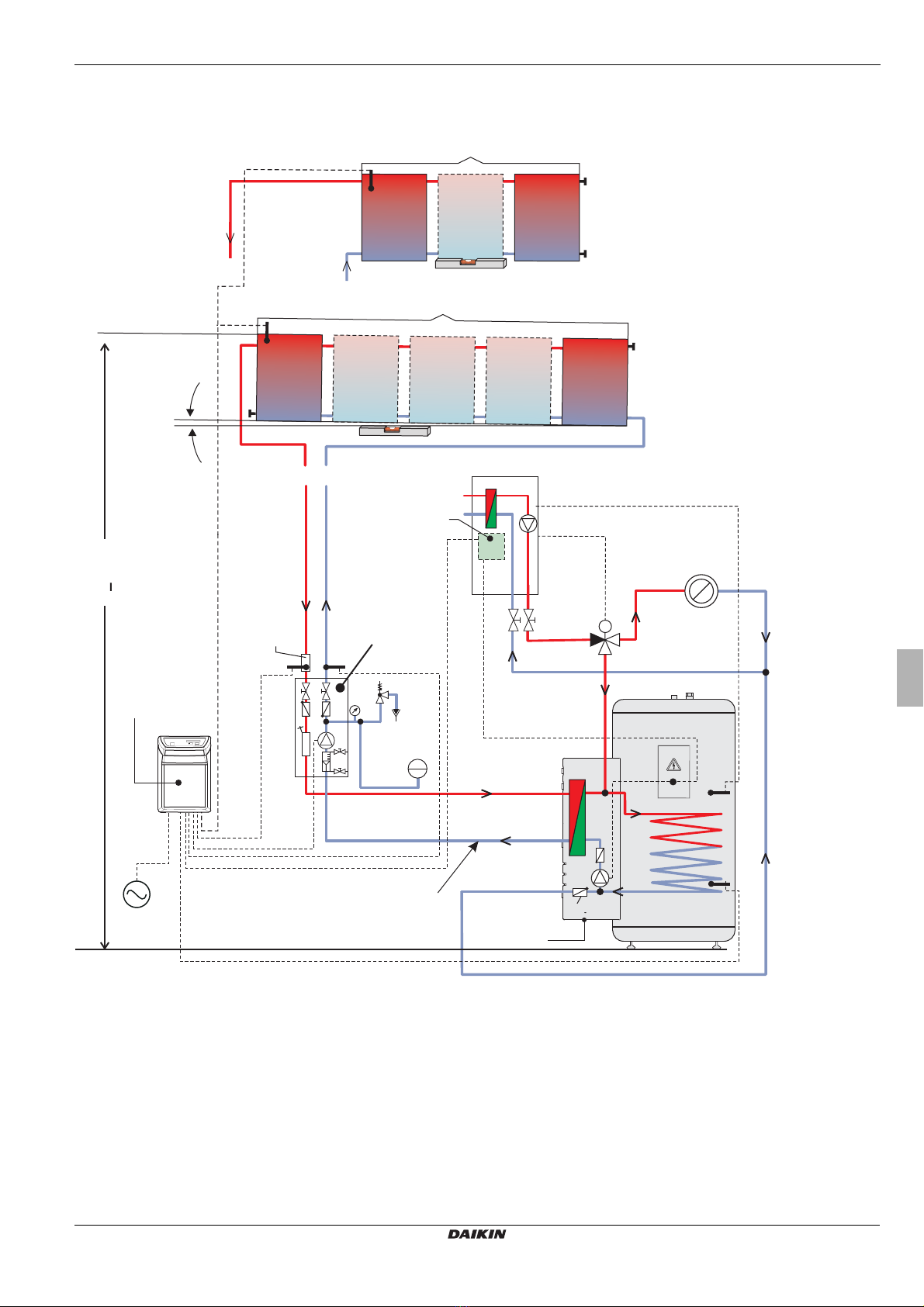
7.2 Diagrams . . . . . . . . . . . . . . . . . . . . . . . . . . . . . . . . . . . . . . . . . . . . . . . . . . . . . . . . . . . . . . . . . . . . . . . . . . . . . . . . . . . . . . . . . . . . . 38
8 List of keywords . . . . . . . . . . . . . . . . . . . . . . . . . . . . . . . . . . . . . . . . . . . . . . . . . . . . . . . . . . . . . . . . . . . . . . . . . . 39

1 xSafety
EKSR3PA + EKSRDS1A
Control and pump unit for solar systems
4PW56033-1
Operating and installation instructions
5
1Safety
1.1 Observing Instructions
This manual is intended for authorised and trained technicians who have experience with the proper installation and start-up of
heating systems on account of their technical training and knowledge.
All procedures required for installation, start-up, operation and adjustment of the installation are described in this instruction
manual and associated instruction manuals. Please read this manual carefully and thoroughly before proceeding with the instal-
lation and initial start-up or modification of the system.
Relevant documents
Documents listed below are part of the technical documentation of the Daikin solar system and therefore must be observed. The
documents are included in the scope of supply of the individual components.
– Air-water heat pumps EKHBH*/ EKHBX*; Operating and installation instructions
– Solar panels EKSV26P/EKSH26P: Installation instructions
– Solar add-on for air-water heat pump system EKSOLHWAV1. Installation and operating instruction manual.
– Process water for air-water heat pump EKHWE*/EKHWS*. Installation instructions
1.2 Warning signs and explanation of symbols
Meaning of the warnings
Warnings in this manual are classified according into their severity and probability of occurrence.
Special warning symbols
Some types of danger are represented by special symbols:
Handling instructions
• Instructions on actions are shown as a list. Actions of which the sequential order must be maintained are numbered.
ÎResults of actions are identified with an arrow.
DANGER!
Draws attention to imminent danger.
Disregarding this warning can lead to serious injury or death.
WARNING!
Indicates a potentially dangerous situation.
Disregarding this warning can result in serious injury or death.
CAUTION!
Indicates a situation which may cause possible damage.
Disregarding this warning can lead to damage to property and the environment.
This symbol identifies user tips and particularly useful information, but not warnings or hazards.
Electrical current Danger of burning or scalding
Materials that are irritants or can damage your health Risk of environmental damage

1 xSafety
Operating and installation instructions
6
EKSR3PA + EKSRDS1A
Control and pump unit for solar systems
4PW56033-1
1.3 Avoid danger
Daikin solar installations are state-of-the-art and are built to meet all recognised technical requirements. However, improper use
can lead to serious injuries or death, as well as cause material damage. To prevent such risks, install and operate the Daikin solar
installation only:
– as stipulated and in perfect condition,
– with an awareness of the safety and hazards involved.
This assumes knowledge and use of the contents of this manual, the relevant accident prevention regulations and the recognised
safety-related and occupational medical rules.
1.4 Proper use
The Daikin solar installation must only be used for heating hot water. The Daikin solar system must be installed, connected and
operated only according to the instructions in this manual.
Any other use outside the above-mentioned use is considered as improper. Any resulting damages will be borne by the user/owner
alone.
Proper use also includes observing the relevant maintenance and servicing conditions. Spare parts must at least satisfy the
technical requirements defined by the manufacturer. This is the case, for example, with original spare parts.
1.5 Instructions for operating safety
Working on the roof
• Installation work on the roof may only be carried out by authorised and trained persons (heating technicians, roofers, etc.) in
compliance with the relevant Accident Prevention Regulations.
• Material and tools must be secured against falling down.
• Barriers must be erected to prevent persons from entering the area below the roof where the work is being carried out.
• Observe safety clearances to overhead lines at the installation location.
Before working on the heating system
• All work on the heating system (such as installation, connection, and start-up) may only be carried out by authorised and
trained heating technicians.
• Switch off the mains supply before starting any work on the heating system and secure it against unintentional switch-on.
Electrical installation
• Electrical installation may only be carried out by qualified electrical technicians under observance of the relevant electrical
guidelines and the regulations of the electric utilities company.
• Before connecting to the mains supply, check that the voltage specified on the type label of the heating system (230 V,
50 Hz) is the same as the available supply voltage.
Instructing the user/owner
• Before you hand over the heating system, explain to the user/owner how to operate and check the heating system.

2 xProduct description
EKSR3PA + EKSRDS1A
Control and pump unit for solar systems
4PW56033-1
Operating and installation instructions
7
2 Product description
2.1 Design and components of the solar system
Fig. 2-1 Standard design of a Daikin solar system (Daikin recommends a double-sided connection)
Power
Mains
EKHB*
EKSOLHWAV1
EKHWS*
EKHWE*
MAG
SV
PS
t
V
4
3
tR
2
1
5
6
tS1
I
tK
II
*
0°
t
K
1
EKRP1HBAA
2
EKSR3PA
EKSGFL
3
EKSFLP12A
M
tS2
EKSRDS1A
<12m
1 Solar panel field
2 Solar feed line (at the top of the solar panels)
3 Solar return line (at the bottom of the solar panels)
4 3-way diverter valve with drive motor
5 Heat distribution
6 Check valve
I Double-sided connection for 2 to 5 solar panels
II Same side connection for max. 3 solar panels (not
for in-roof installation)
EKHB* Internal unit of the air-water
heat pump
EKHWE*/EKHWS* Hot water storage tank
EKRP1HBAA Solar module
EKSFLP12A FlowSensor (accessory)
EKSGFL Solar system fluid
EKSOLHWAV1 Solar connection kit
EKSRDS1A Pump unit
EKSR3PA Control unit
MAG Diaphragm pressure expansion vessel (building
side)
PSSolar panel circulation pump
SV Pressure relief valve
tKSolar panel temperature sensor
tVSolar flow temperature sensor
tRSolar return flow temperature sensor
tS1 S
torage temperature sensor in air-water heat pump
t
S2
Storage temperature sensor in the controller
EKSR3PA

2 xProduct description
Operating and installation instructions
8
EKSR3PA + EKSRDS1A
Control and pump unit for solar systems
4PW56033-1
2.2 Brief description
The Daikin solar system is a thermal solar system for supplying hot water.
Operating mode
The high-performance flat solar panels EKSV26P and EKSH26P efficiently convert the sun's radiation into heat.The heat-transfer
medium in the solar panel system is a frost-proof water-glycol mixture, and heating water in the tank circulation system.
When the solar panels reach a usable temperature level the fluid in the solar panel circuit EKSGFL is pumped by the pump unit
EKSRDS1A and the plate heat exchanger of the solar connection kit EKSOLHWAV1. The circulation pump of the solar connection
kit EKSOLHWAV1 (solar panel circulation pump) simultaneously pumps the heating water in the storage tank charging circuit
through the plate heat exchanger where it takes up the heat given out by the solar panel circuit and transfers it to the hot water
via the storage charging heat exchanger.
Modular design
The system consists of several preassembled modules. Plug-in technology and a high degree of pre-assembly ensure fast and
simple installation.
Storage tank
Only the hot water storage tanks EKHWE*/ EKHWS* can be used for the Daikin solar system.
Electronic control
The fully electronic control system of the controller EKSR3PA ensures optimum utilisation of the solar heat (hot water generation)
and that all safety-relevant aspects are complied with. All parameters needed for trouble-free operation have been preset at
factory.
2.3 System components
Controller EKSR3PA
Construction, operating principle, commissioning, and operation of the storage tank are not described in this manual.
You will find detailed information on the storage tanks in their respective installation and operating manuals.
The Daikin solar system can only be operated with the air-water heat pump EKHBX*, the pump unit EKSRDS1A,
the controller EKSR3PA, the solar connection kit EKSOLHWAV1, the water-glycol mixture EKSGFL and the hot
water storage tanks EKHWE*/ EKHWS*.
Consists of:
– Controller EKSR3PA with storage temperature sensor,
return flow temperature sensor with sensor adapter,
connection plug solar panel temperature sensor, pump
connection and extension cable (PS), connection cable for
solar priority, connection cable 230V mains connection
(3 m)
– Accessory bag (4 fillister screws, 4 plugs,
2 locking screws)
– Documentation
Fig. 2-2 Controller EKSR3PA

2 xProduct description
EKSR3PA + EKSRDS1A
Control and pump unit for solar systems
4PW56033-1
Operating and installation instructions
9
Pump unit EKSRDS1A
Solar connection kit EKSOLHWAV1
Solar module EKRP1HBAA
2.4 Accessories
FlowSensor EKSFLP12A
Pump unit including connection fittings for Cu pipe Ø 22 mm
with circulation pump Grundfos Solar 25-65,
diameter with 2x KFE cocks, integrated air separator, safety
group with pressure gauge, fitting accessories.
Fig. 2-3 Pump unit EKSRDS1A
To connect the pump unit EKSRDS1A with the hot water
storage tank EKHWE*/EKHWS*.
Consists of:
– Plate heat exchanger
– Circulation pump
– Fitting material
Fig. 2-4 Solar connection kit EKSOLHWAV1
For connecting the air-water heat pump EKHBH*/ EKHBX* to
the Daikin solar system.
Consists of:
– Solar board
– Connection cables
– Fitting material
Fig. 2-5 Solar module EKRP1HBAA
A4P
For measuring the flow volume and the feed temperature.
Consists of:
– FlowSensor with pressure and temperature resistant
measuring section and pre-assembled pipe adapter
– 3 m cable (ready to plug in).
Fig. 2-6 EKSFLP12A FlowSensor supplied with 3 m cable

3 xInstallation
Operating and installation instructions
10
EKSR3PA + EKSRDS1A
Control and pump unit for solar systems
4PW56033-1
3 Installation
3.1 System concepts
DAIKIN solar systems are usually set up according to one of the following system layouts.
3.1.1 Parallel connection
3.1.2 Serial connection
As an alternative to the straightforward parallel connection, as described, the solar panels can, if required, also be mounted in a
maximum of three rows one above the other. Solar panels or solar panel fields mounted one above the other must be connected
in series (Fig 3-3). One pack of serial connectors for the selected solar system will be required for each additional row of solar
panels.
3.2 Preparatory installation work
Fig. 3-1 Solar panel connected at both sides
(recommended)
Fig. 3-2 Solar panel field with both connections at one end
(max. 3 solar panels)
1Solar panel connector
2Mounting profile rail
3Solar panel securing clip
4Solar panel
5Return connection solar panel
6Flow connection solar panel
7Solar panel connection cap
8Roof penetration for flow and return flow
9Solar return line
10 Solar flow line
11 Solar panel serial connector
12 Solar panel field (2x 2 solar panels)
Fig. 3-3 Alternative solar panel arrangement
WARNING!
Live parts can cause an electric shock on contact and cause life-threatening burns and injuries.
• Before beginning installation and maintenance work, disconnect the electrical components from the
power supply (switch off fuse, main switch) and secure against unintentional restart).
• Electrical installations must always be carried out by qualified electrical technicians in conformity with
the relevant electrical guidelines and the regulations of the electric utilities company to prevent hazards
from damaged electric wiring.
• Comply with the relevant safety at work regulations.

3 xInstallation
EKSR3PA + EKSRDS1A
Control and pump unit for solar systems
4PW56033-1
Operating and installation instructions
11
1. Fit solar connection kit EKSOLHWAV1 to hot water storage tank. See installation instructions for solar connection kit.
2. Install the solar module EKRP1HBAA in the internal unit of the air-water heat pump EKHBH*/ EKHBX*. See installation
instructions for solar module.
3. Fit solar panel temperature sensor. See installation instructions for solar panels EKSV26P/ EKSH26P.
3.3 Pump unit EKSRDS1A
DANGER!
Leaking gas in the immediate proximity of electrical components can cause an explosion.
• The Control and pump unit for solar systems EKSR3PA + EKSRDS1A and electrical components should
not be installed in locations where there is a danger of flammable gas escaping.
• Pay attention to minimum distances from walls and in shafts.
CAUTION!
If the circulation in the solar panels comes to a standstill, steam may be formed and may damage the
diaphragm expansion vessel (MAG).
• Always install the EKSRDS1A pump unit and the diaphragm expansion vessel (MAG) lower than the solar
panels.
CAUTION!
Danger of scalding if incorrect connection pipes are used.
• The connection pipe between the solar panel array and the hot water storage tank must be made of
pressure-resistant metal piping (recommended Cu Ø 22 mm). Using plastic piping is not allowed.
1 Outside cover
2 Temperature gauge on solar return line
3 Temperature gauge on solar feed line
4 Connection of solar return line (Ø 22 mm)
5 Connection of solar feed line (Ø 22 mm)
6 Safety valve with pressure gauge (solar panel circuit)
7 Connection of diaphragm expansion vessel (MAG) (Ø 22 mm)
8 Circulation pump (solar panel circuit)
9 Filling and drainage cock (solar panel circuit)
10 Flowmeter (solar panel circuit)
11 Connection of pump unit feed pipe to solar connection kit
EKSOLHWAV1 (Ø 22 mm)
12 Connection of pump return line to solar connection kit
EKSOLHWAV1 (Ø 25 mm)
13 Drilled holes for mounting the pump unit on the wall
14 Venting pot
Fig. 3-4 Connections and dimensions pump unit EKSRDS1A
EKHB* EKHB*
EKSRDS1A
EKSRDS1A
14

3 xInstallation
Operating and installation instructions
12
EKSR3PA + EKSRDS1A
Control and pump unit for solar systems
4PW56033-1
1. Remove external cover (1) over the pump unit EKSRDS1A.
2. Mount the pump unit EKSRDS1A on the wall in the vicinity of the hot water storage tank.
3. Mount the sensor adapter pipe for return flow temperature sensor tRon the solar return flow on top of the pump unit
EKSRDS1A (connection 4).
4. Optional: Mount FlowSensor EKSFLP12A on the solar flow at the top on the pump unit EKSRDS1A (connection 5)
(see Chapter 3.7).
5. Connect the feed and return lines (Cu Ø 22 mm) from the solar panel (see Chapter 3.1), at the top of the pump unit
EKSRDS1A (connections 4 and 5) in accordance with the system design.
6. Install the feed and return lines (Cu Ø 22 mm) between the pump unit EKSRDS1A (connections 11 and 12) and the solar
connection kit EKSOLHWAV1.
7. Connect the diaphragm pressure expansion vessel (MAG) to the pump unit EKSRDS1A (connection 7). Connect the
diaphragm expansion vessel in accordance with EN 12828.
8. Connect the blow-off line to the safety valve in accordance with EN 12828.
– The blow-off line should be routed so that solar liquid can flow freely into a collection vessel when the safety valve is
tripped.
– The blow-off line should be able to be blocked off.
3.4 Controller EKSR3PA
3.4.1 Wall mounting
General installation instructions
– The pump unit EKSRDS1A should be mounted in such a way that there are no external forces act on the
fittings when installed.
– Welding and soldering work on the plant should not cause any overheating. Fit the pump unit EKSRDS1A
only after this work has been carried out.
– The pipes must be flushed out thoroughly before installing the pump unit EKSRDS1A to prevent leaks
caused by weld spatter, hemp or metallic swarf.
Installing the clamping ring bolt:
• Cut off the pipe end at right angles and debur.
• Place swivel nut and clamping ring on the pipe.
• Lightly oil threads.
• Push pipe into the clamping ring bolt to the stop and tighten swivel nut by hand.
• Tighten swivel nut with open-ended spanner.
1. Unscrew the screws on both sides of the cover.
2. Fold the cover forward and remove downwards.
3. Unhook the control system from the housing baseplate.
4. Mount the housing baseplate in the vicinity of the pump unit
EKSRDS1A on the wall.
Fig. 3-5 Removing and fixing the control unit
1
1
2
3
2x
2x

3 xInstallation
EKSR3PA + EKSRDS1A
Control and pump unit for solar systems
4PW56033-1
Operating and installation instructions
13
3.4.2 Electrical connections
1. Check the power supply voltage at the house junction box (~230 V, 50 Hz).
2. Disconnect the junction box of the domestic installation.
4. Fix the cable supplied to the back of the control system using the edge connectors. The plugs are coded to prevent mixing
them up. The configuration of connections is shown on the lid of the control system.
5. Connect solar panel temperature sensor line (integrated in the connection cable) to the terminals in the plug and connect the
plug on the edge of the board of the control system, to position TK (2-pole, see Fig 3-10).
6. Optional: Connect the FlowSensor EKSFLP12A plug (see Chapter 3.7).
7. All the cables are routed through the labyrinth to ensure there is stress relief.
3. Lay the connection cable from the control unit EKSR3PA to the
individual components and connect.
– Power supply (~230 V, 50 Hz)
– Solar panel temperature sensor tK(included in the scope of
supply of the solar panel components)
– Return flow temperature sensor tR
– Solar panel circulation pump PSof the pump unit EKSRDS1A
– Board A4P of the solar module EKRP1HBAA
– Storage temperature sensor tS2
– Optional:Flow meter tV(FlowSensor EKSFLP12A)
Fig. 3-6 Electric cabling EKSR3PA
Fig. 3-7 Steps 4+5 Fig. 3-8 Steps 4+5 Fig. 3-9 Step 7
tS1
tS2
EKHB*
EKHWS*
EKHWE*
tK
A4P
PS
~

3 xInstallation
Operating and installation instructions
14
EKSR3PA + EKSRDS1A
Control and pump unit for solar systems
4PW56033-1
8. Place control systems into the housing baseplate from above.
9. Hook the cover into the bottom of the housing baseplate and click into the control system at the top.
10. Screw cover on both sides to the control system housing again with countersunk screws.
11. Lay the cable to the components.
12. Connect the cable for solar priority (points 1+4 in the Figures 3-13 and 3-14) to the board A4P of the solar module
EKRP1HBAA and the connection X2M of the internal unit of the air-water heat pump.
Fig. 3-10 Connection assignment
CONF Programming socket for software updates
FLS FlowSensor EKSFLP12A (accessory)
TS Storage temperature sensor tS2
TR Return flow temperature sensor
TK Solar panel temperature sensor
BSK Connection cable for solar
priority
P1/P2 Solar panel circulation
pump PS
F1 Fuse
Power Power supply
Fig. 3-11 Basic cabling: tank, solar panel sensor, pump and power
feed
Fig. 3-12 Extended cabling additionally with FlowSensor
Fig. 3-13 Connection cable for solar priority on EKHBH/X_AA and
EKHBH/X_AB
Fig. 3-14 Connection cable for solar priority on EKHBH/X_BA
19 20 21
1243
P2 P1 19 20
YC Y3
P
N L
P
N L
NL123L N
A4P
X2M
P1/P2 BSK
X8M
X10M
EKHWS*
EKHWE*
EKHB*AA/EKHB*ABEKSR3PA
EKSOLHWAV1EKSRDS1A
32 1
4
5
13a
21 28 29
1243
P2 P1 19 20
X3 X4 YC Y3
P
N L
P
NL
NL123L N
A4P
X2M
P1/P2 BSK
X8M
X10M
EKHWS*
EKHWE*
EKHB*BAEKSR3PA
EKSOLHWAV1EKSRDS1A
32 1
4
5

3 xInstallation
EKSR3PA + EKSRDS1A
Control and pump unit for solar systems
4PW56033-1
Operating and installation instructions
15
3.5 Pump unit EKSRDS1A - electrical connection
1. Remove cover on switch casing of solar panel circulation pump.
2. Connect control line to solar panel circulation pump.
3. Install cover on switch casing of solar panel circulation pump.
4. Lay control line in casing of EKSRDS1A pump unit.
5. Replace the external cover (1) on the pump unit EKSRDS1A.
3.6 Storage temperature sensor
Fig. 3-15 Work step 2 Fig. 3-16 Work step 3 Fig. 3-17 Work step 4
• Insert the storage temperature
sensor tS2 (included in supply) into
the bottom connection on the hot
water storage tank.
Fig. 3-18 Position storage temperature
sensor
Fig. 3-19 Installation storage temperature
sensor tS2
tS1
tS2
EKSOLHWAV1

3 xInstallation
Operating and installation instructions
16
EKSR3PA + EKSRDS1A
Control and pump unit for solar systems
4PW56033-1
3.7 FlowSensor (optional)
• During installation be aware of the flow direction of the measurement instruments.
• The FlowSensor and the measuring section must not be overheated by welding and soldering work on
the plant. Only fit the measuring section after this work.
• Tighten the screwed fittings after final installation of the measuring section.
The FlowSensor EKSFLP12A (Page 9, Fig 2-6 ), available as an accessory, is
a measurement instrument that records the flow volume in the solar panels
and the feed temperature. The measurement range of the FlowSensor
EKSFLP12A is between 0 and 12 l/min (flow volume) and 0 to 120 °C (feed
temperature).
The measured values are shown on the control unit EKSR3PA display. The
control system EKSR3PA automatically sets the appropriate flow rate when
the system is in operation by regulating the speed of the solar panel circulation
pump.
1. Slide the swivel nut (2) and the cutting ring (1) over the pipe adapter (3)
at the outlet of the FlowSensor (4).
2. Push the pre-assembled FlowSensor (4) onto the flow connection of the
control unit EKSR3PA and tighten the swivel nut (2).
3. Lay the FlowSensor cable (5) between FlowSensor (4) and the control
unit EKSR3PA.
4. Connect FlowSensor cable (5) to FlowSensor (4) and to the control
system printed circuit board edge at position FLS (4-pin, see Fig 3-10).
Fig. 3-20 Installation FlowSensor EKSFLP12A
1
2
2
3
4
5

4 xStart-up and taking out of service
EKSR3PA + EKSRDS1A
Control and pump unit for solar systems
4PW56033-1
Operating and installation instructions
17
4 Start-up and taking out of service
4.1 Initial start-up
4.1.1 Filling solar panel circuit
Tab. 4-1 Calculating pressures for start-up
1. Check that all threaded fasteners are tight.
2. Calculate the required initial pressure for the diaphragm expansion vessel (MAG) with the system unpressurised, check it
and adjust if necessary (see MAG initial pressure Tab. 4-1).
3. Open ball cock ball valves of feed and return flow at the EKSRDS1A pump unit.
4. Set the blocking of the flow meter (Item 10, Fig 3-4) to the filling position (slot horizontal).
WARNING!
The solar system cannot be started until all hydraulic and electrical connections have been completed.
An incorrect start-up will adversely affect the function and may damage the complete system. Installation and
start-up must therefore must conducted by DAIKIN-authorised and trained heating experts.
CAUTION!
Danger of scalding by hot solar fluid and escaping steam.
• Only fill the solar panel circuit when there is no strong direct sunlight or only if the solar panels are covered
up.
WARNING!
If the heat transfer medium is mixed with other substances, frost and corrosion protection may be reduced.
This may damage system components.
• Conduct all work on the components of the solar system only with the solar panels covered.
• The solar system should only be flushed and filled with the included heat transfer medium EKSGFL.
• Mixing of the heat transfer medium with other materials is not permitted.
WARNING!
If heat transfer media containing glycol are exposed to temperatures above 170 °C over an extended period,
they will decompose or form silt. This may reduce the frost protection, affect the output of the solar system
and damage components of the system.
• Start operation of the solar system immediately after filling it.
• Drain the system if it is to be out of operation over an extended period.
• Replace the heat transfer medium in the system before start-up after extended downtime.
MAG initial pressure System fill pressure Maximum system pressure
pv= 0.1 x hstat + 0.5 bar p0= pv+ 0.3 bar pe<= 0.9 x psv
peMaximum permissible system pressure
(hot) in bar
psv Operating pressure of safety valve
(>3 bar)
pvMAG initial pressure in bar
(at least 1.2 bar)
p0System filling pressure (cold) in bar
hstat Static height in m between centre of
MAG and the highest point of the system.

4 xStart-up and taking out of service
Operating and installation instructions
18
EKSR3PA + EKSRDS1A
Control and pump unit for solar systems
4PW56033-1
5. Connect filling/flushing pump by hose to the upper KFE cock (see also Item 9, Fig 3-4) of the pump unit EKSRDS1A.
6. Connect the return hose to the lower KFE cock (see also Item 9, Fig 3-4) of the pump unit EKSRDS1A and direct to the filling
container from which the solar fluid EKSGFL is to be filled into the solar panel circuit.
7. Open KFE cocks and start filling/flushing pump.
8. Fill and flush the solar panel circuit until the solar fluid flows back into the filling container cleanly and without any bubbles.
9. The pressure at the pressure gauge of the pump unit EKSRDS1A must not exceed the maximum permissible system pressure
pe(Tab. 4-1).
10. Close the lower KFE cock.
11. Increase the solar panel circuit pressure to at least 0.3 bar above the pressure set at the diaphragm expansion vessel (MAG)
(see system fill pressure Tab. 4-1).
12. Close the upper KFE cock.
13. Vent the system as follows :
• Direct the venting hose of the venting pot into a suitable collection vessel.
• Open valve (Item 3, Fig 4-1) of the venting pot (Item 1, Fig 4-1).
ÎDisplaced air escapes from the venting pot.
• Close the valve as soon as solar fluid comes out of the venting pot.
14. Check the system pressure on the pressure gauge of the pump unit EKSRDS1A again.
– The system pressure must not drop over a period of 1/2 hour.
– If the pressure drops, check the solar panel circuit and connections for leaks and repair if necessary.
– Vent solar panel circuit again (residual air in system).
– If necessary, correct the system pressure by adding solar fluid (see working step 4 onwards).
15. Separate the filling/flushing pump with hoses from the pump unit EKSRDS1A.
16. Open the blocking of the flow meter completely (slot vertical).
Fig.4-1 Filling and venting the solar panel circuit
EKHB*
EKSRDS1A
1
2
3

4 xStart-up and taking out of service
EKSR3PA + EKSRDS1A
Control and pump unit for solar systems
4PW56033-1
Operating and installation instructions
19
4.1.2 Regulate the flow rate on the solar panel circuit
1. Connect the mains line of the control unit EKSR3PA to the plug socket of the domestic supply (~230 V, 50 Hz) and provide
power supply.
2. Switch on the control unit EKSR3PA (initialisation phase starts).
3. After the initialisation phase (temperature display), start the system by pressing the two arrow keys simultaneously (manual
operation).
ÎThe pump then runs up to its full output.
4. Close the regulating valve (closing the flow meter) completely. The system is now under the maximum possible operating
pressure.
5. Look for leaks by carrying out a visual examination of all connection points in the house and on the roof. Repair any leaks
found.
6. Finish heat insulation at connection points.
7. Adjust flow depending on the number of solar panels. For reference values for the setting see Tab. 4-2.
Tab. 4-2 Setting the flowrate on the flow meter
8. Switch the control unit EKSR3PA off.
9. Instructing the user/owner
4.1.3 Filling the storage tank and heating circuit
• Filling the hot water storage tank; see the associated installation and operating instructions.
• Filling the heating system and venting; see the associated installation and operating instructions.
The pumps are only switched on if the temperature of the solar panels is higher than the minimum value coupled
to the minimum temperature of the storage tank (see chapter 5.2.10) and lower than the specified approved
maximum temperature.
If there is a longer period between step 5 and 8, the temperature of the solar panels may be outside the
approved range. If TK> TKzul it is not necessary to switch to manual operation.
Number of
solar panels
Set flow rate in l/min
on solar panel circuit
Set flow rate in l/h
on solar panel circuit
2 3.6 to 4.8 220 to 290
3 5.4 to 7.2 330 to 435
4 7.2 to 9.6 435 to 580
5 9 to 12 540 to 720
The flow of the solar panel circuit can be checked and set at the flow display of the DAIKIN pump unit
EKSRDS1A (settings see Tab. 4-2).
When using the FlowSensors EKSFLP12A completely open the regulating valve.
ÎThe optimum flow rate is automatically adjusted by regulating the speed of the pump.
ÎAt the same time the control system performs an output measurement and energy balance.

4 xStart-up and taking out of service
Operating and installation instructions
20
EKSR3PA + EKSRDS1A
Control and pump unit for solar systems
4PW56033-1
4.2 Taking out of service
4.2.1 Temporary shutdown
If solar heating support is not required for water heating for an extended period, the solar system can be switched off temporarily
at the mains switch of the EKSR3PA control unit.
In the event of frost danger you must:
– start the solar system in operation
or
– suitable antifreeze measures must be applied to the connected heating system and hot water storage tank (e.g. draining).
4.2.2 Final shutdown
• Switch on the EKSR3PA + EKSRDS1A control and pump unit again (see Chapter 4.2.1 "Temporary shutdown“).
• Disconnect the EKSR3PA + EKSRDS1A control and pump unit from all electrical and water connections.
• Dismantle the EKSR3PA + EKSRDS1A control and pump unit in accordance with the assembly instructions (Chapter 3
"Montage“) in reverse order.
• Dispose of the EKSR3PA + EKSRDS1A control and pump unit correctly.
Recommendations for disposal
CAUTION!
A heating system which is shut down can freeze in the event of frost and may suffer damage.
• Drain the heating system that is shut down if there is danger of frost.
If there is a danger of frost for just a few days, the unit's excellent heat insulation means that the insulated tank
does not have to be drained, provided that the storage tank temperature is monitored regularly and does not fall
below +3°C. This does not, however, provide any protection against frost for the connected heat distribution
system!
Thanks to the environmentally friendly design of the solar system, DAIKIN has complied with requirements for
environmentally sound disposal. During the disposal process, the only waste created is that which can be used
for material or thermal recycling.
The materials that are suitable for recycling can be separated so that they are unmixed.
This marking on the product indicates that electrical and electronic products must not be disposed of in unsorted
household waste.
Proper disposal in compliance with the applicable national regulations of the country of use is the responsibility
of the user/owner.
• Dismantling the system, handling refrigerant, oil and other parts may only be carried out by a qualified
technician.
• Disposal only via an organisation specialised in reutilisation, recycling and recovery.
Further information can be obtained from the installation company or from the responsible local authority.
This manual suits for next models
1
Table of contents
Other Daikin Water Pump manuals

Daikin
Daikin Altherma 3 GEO How to use

Daikin
Daikin Altherma R Hybrid Product information sheet

Daikin
Daikin Rotex RPS4 User manual

Daikin
Daikin Rotex PGMK User manual

Daikin
Daikin SUT Series User manual

Daikin
Daikin MicroTech III User manual

Daikin
Daikin EKSRDS2A User manual

Daikin
Daikin Altherma 3 GEO EGSAH06UDA9W User manual
Popular Water Pump manuals by other brands

CAT Pumps
CAT Pumps 241 Service manual

Pentair
Pentair EASYBOOST PRESSOMAT instruction manual

Danfoss
Danfoss H1 Series technical information

Varian
Varian VHS-10 instruction manual

Ashland
Ashland ANC200 OPERATION, PERFORMANCE, SPECIFICATIONS and PARTS MANUAL

Huntleigh
Huntleigh AlphaXcell Electric Service manual