5
3. INSTALLATION REQUIREMENTS
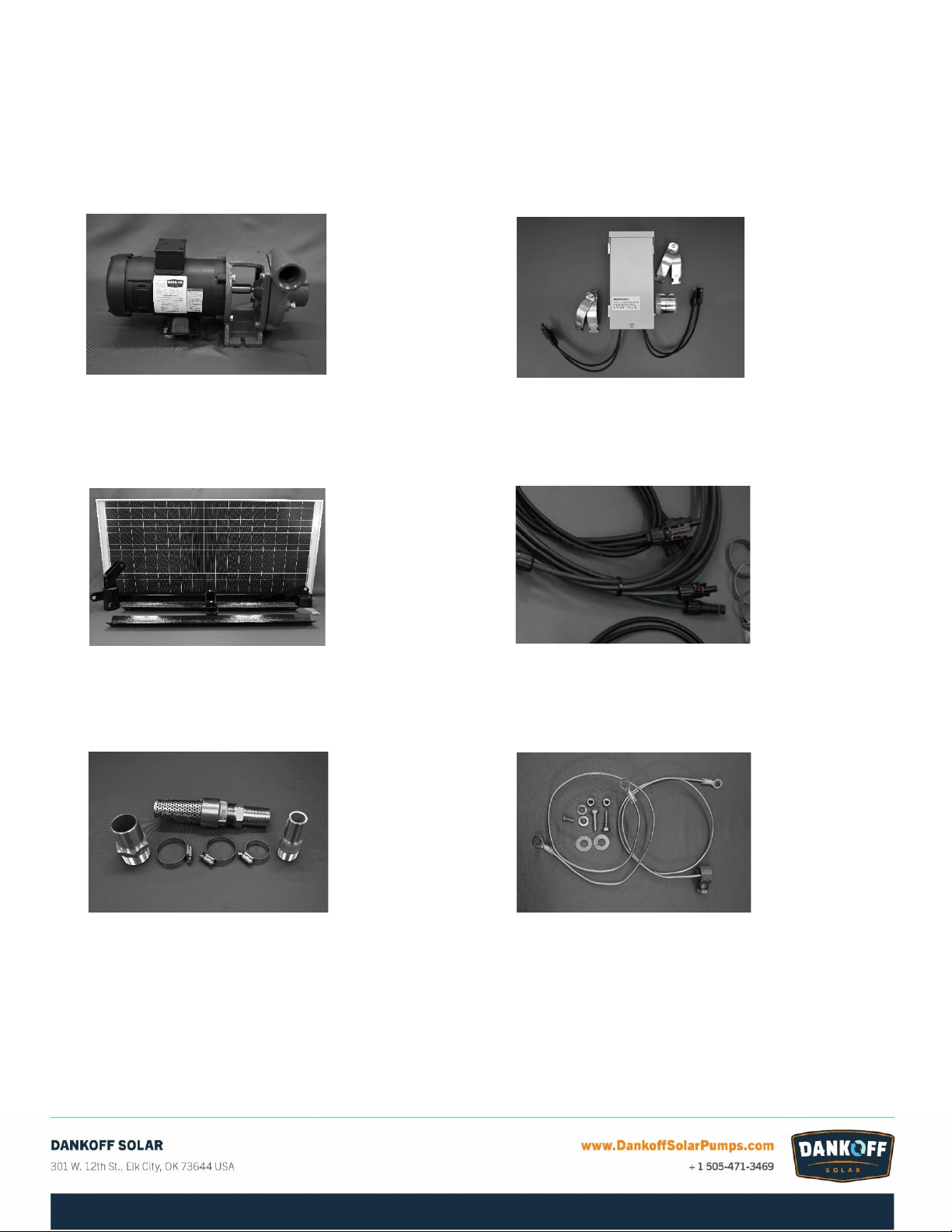
Kit Overview
The Water Feature Solution Kit is designed for plug-and-play installation and comes complete with all the necessary
hardware and fittings to do so. Because each installation is different a few locally purchased components are
required to complete installation:
-Hoses –Dankoff Solar recommends flexible suction and discharge hoses, and The Water Feature comes
with the necessary fittings and clamps for this type of hose. Inlet hose size is 1 ¼” and outlet hose size is
1”. Simply ask for ‘suction hose’ at your local hardware supply store to purchase the lengths you will need
for your installation
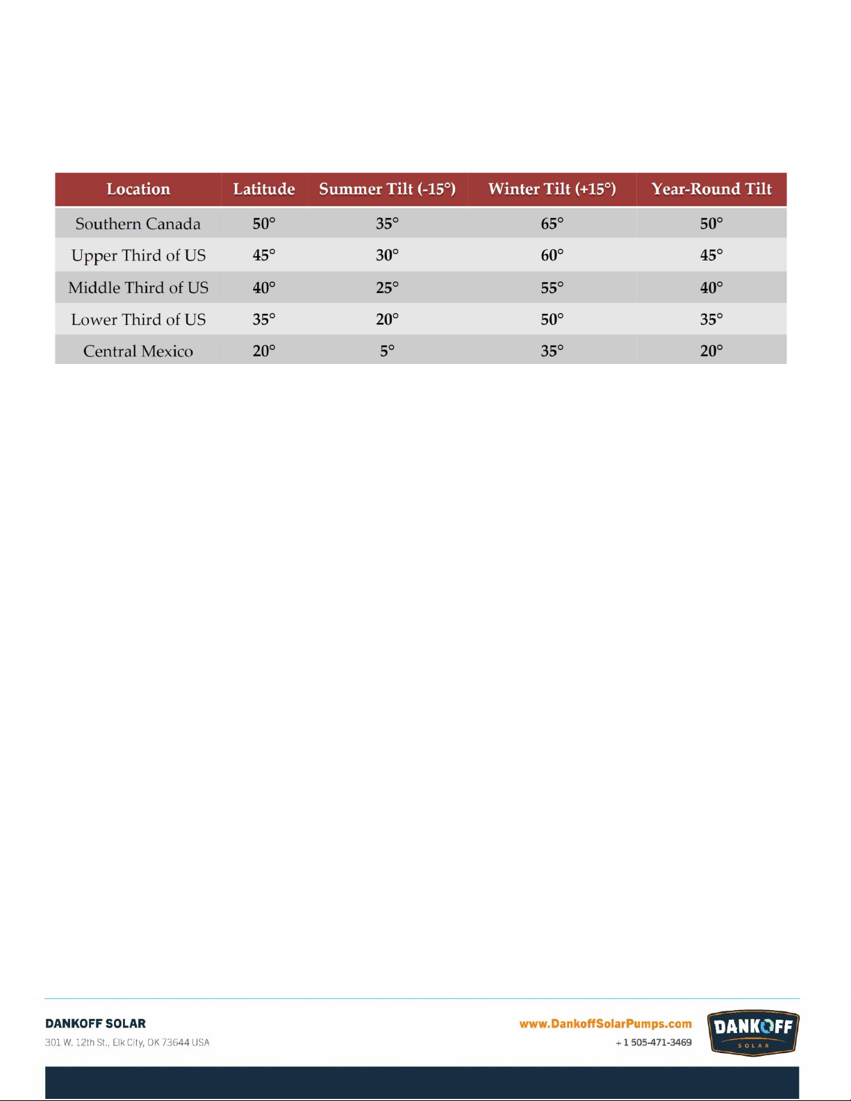
-Rack Mounting Pole –The Panel Rack in The Water Feature Solution Kit includes a gimble that will accept a
3” mounting pole. Dankoff Solar recommends using Schedule 80 pipe, installed 36” below the frost line
using Quickrete, with a minimum of 36” above the ground to accept the rack. PV’s must not be shaded or
blocked at any point during the day to get the stated performance.
-Grounding Rod –Because of the ready availability and to reduce the shipping weight of The Water Feature
Solution Kit, all of the components to properly ground the system are supplied, with the exception of the
grounding rod itself, which can be purchased at any hardware or electrical supply store.
-Pump House/Cover –Because every installation environment is different, the Solution Kit does not include
a generic pump house to shield the pump from the elements, since the pump can be installed in a variety of
ways. Dankoff Solar recommends that the SunCentric pump be shielded from the elements to get the most
out of its 20 year life, and there are many available options that can be purchased locally.
Some ideas include: a curved piece of sheet metal with open ends (the cover should be twice as long as the
pump); a metal barrel cut in half the long way and placed over the pump; any weatherproof box inverted
over the pump; a dog house set it over the pump with the pipes passing through the doorway.
Non-submersible pumps
Do not submerge pump or motor in water, or allow water to drip on the motor.
Filtration requirements
SunCentric Pumps are somewhat dirt tolerant and can be run from many clean water sources without filtration.
However, to prevent possible large debris contamination and to help keep the pump primed, a Dankoff Solar Fine
Intake Strainer Foot Valve (PN –11044) has been provided with the proper fittings.
Pump must not run dry
Water is the lubricant for the pump. If the pump runs completely dry, it will overheat and fail. If pumping from a
tank, cistern or any water source that can run low accidentally, we recommend using a float switch.
A float switch (PN –11004, pump down switch) placed in the supply tank closes when the tank water supply is at a
high level. When the water level drops to a low level, the switch will open and remove power from the pump motor.
This has not been supplied with The Water Feature Solution Kit, as it will only be used in a limited number of
Customer applications.