Dantherm Flexibox 810 User manual

Flexibox 810 indoor
Service manual
Rev. 1.0
en •de

Der tages forbehold for trykfejl og ændringer
Dantherm can accept no responsibility for possible errors and changes
Irrtümer und Änderungen vorbehalten
Dantherm n’assume aucune responsabilité pour erreurs et modifications éventuelles
Dantherm no asume ninguna responsabilidad sobre posibles errores o modificaciones

1
086783•Version 1.0 12.6.2014
en
Introduction
Overview
Introduction
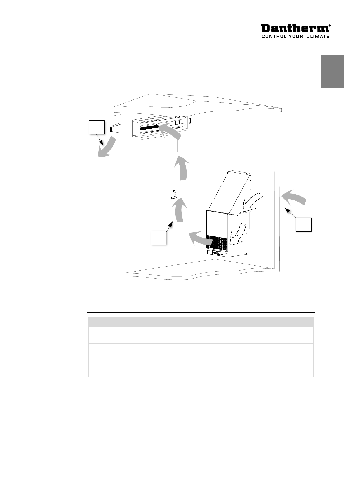
This is the service manual for the
Dantherm Flexibox 810 indoor part number 368454
Please see the below table of content for further information about the sections.
Manual
Part number of this service manual is
086783 and covers units with serial numbers
from
1405200000001
Target group
The target group
for this service manual are the technicians who install and maintain
the Flexibox 810 indoor, as well as the users of the unit.
Copyright
Copying of this service manual, or part of it, is forbidden without prior written permi
s-
sion from Dantherm Air Handling A/S.
Reservations
Dantherm reserves the right to make changes and improvements to the product and the
service manual at any time without prior notice or obligation.
Table of contents
This service manual covers
the following main topics:
Introduction
................................................................................................................1
Product description..............................................................................................2
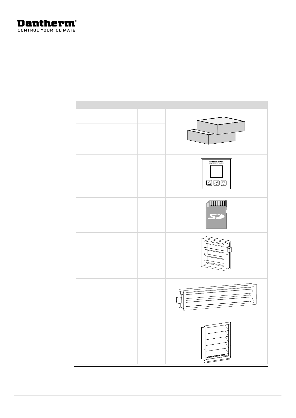
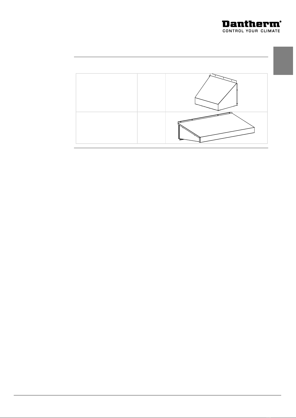
Accessories..........................................................................................................6
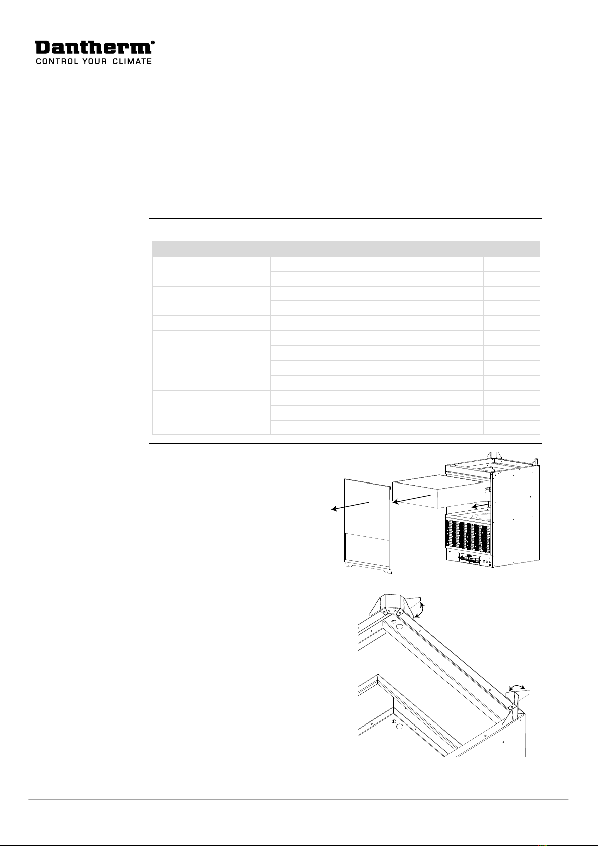
Flexibox installation.............................................................................................8
Damper installation............................................................................................14
Electronic controller
..................................................................................................16
Connections.......................................................................................................19
Controller operation strategy .............................................................................22
Changing parameters.........................................................................................24
Digital input.......................................................................................................27
Service guide
............................................................................................................28
Preventive maintenance......................................................................................29
Troubleshooting ................................................................................................31
Electrical schematic............................................................................................32
Spare part list ....................................................................................................33
Technical data ...................................................................................................34
AC control .........................................................................................................37
Index .................................................................................................................38

2
Product description
Introduction
This section describes the overall product, and its functionality
Usage of the
Flexibox 810 in-
door
Flexibox 810 indoor
is designed to control the internal temperature of an outdoor tele-
com
enclosure.
Flexibox 810 indoor
is designed to maintain correct temperature for electronic equip-
ment, by removing dissipated heat from the electronics shelter.
Important
Dantherm
recommends that any cooling system should be operating continuously, in
order to maintain flawless telecom services around the clock.
Outdoor view
This illustrates the unit parts
Fig. 1
Parts description
outdoor view
This tables shows outdoor parts according
to Fig. 1
Part
Function
1
Front cover
2
Filter
3
Filter lock frame
4
Ambient temp sensor
5
Safety grill
6
CC4 controller board
7
Fan
8
Filter guard pressure transducer
9
Wall bracket
Continued overleaf
567
9
12
8
34

3
086783•Version 1.0 12.6.2014
en
Product description,
continued
Indoor view
This illustrates the unit in
door visible parts
Fig. 2
Parts description
indoor view
This tables shows indoor parts according
Fig. 2
Part
Function
1
Air inlet grill
2
Controller connection
3
Earth connection
Continued overleaf
2
3
1

4
Product description,
continued
Cooling
operation
The Flexibox controller continuously monitors the inside as well as the outside air te
m-
perature, and select appropriate operation mode accordingly.
Mode
Description
External heating If the inside temperature is lower than the heat setpoint (“Heater
SetPt.”) parameter, any external heater connected to the Flexibox,
will be activated.
Free cooling If the inside temperature is higher than setpoint, the internal fan of
the Flexibox starts up slowly, and increases/decreases speed, to
maintain the setpoint temperature.
Free cooling operation is dependent on a lower outside than inside
temperature.
In Free cooling operation, the damper will open, to emit warm air to
the outside surroundings.
External
AC cooling
If the inside temperature is higher than setpoint, and outside air is
higher than inside, minus the temperature delta of 3° by default, the
Flexibox will change to external AC mode, if connected.
In this operation mode, the damper is closed.
Alarms The controller can issue various alarms, on any of the two alarm
connections. This can be set up in the configuration. See more at
page 26
By default the alarms is setup to:
•Alarm output 1 is operation error alarms, that needs immedi-
ate attention
•Alarm output 2 is activated by the filter surveillance. This
doesn’t need immediate action, and could be handle as an
warning
Continued overleaf

5
086783•Version 1.0 12.6.2014
en
Product description,
continued
Cooling air flow
The illustration and table below
describes the free cooling airflow of a Flexibox 810 in-
door
setup
Fig. 3
Cooling
Phase
Description
1 Cold outside air is drawn into the Flexibox through the air filter, and sup-
plied into the warmer shelter
2 Cold air will mix with the warmer air, and push the warmest air towards the
ceiling
3 The open damper placed near the ceiling, releases the warm air to the out-
side surroundings
3
2
1

6
Accessories
Introduction
The Flexibox is a standalone free cooling fan box with a built in main controller.
In order to get at full fledge
cooling system various items can be purchased from Dan-
therm
Accessory list
The following accessories is available for Flexibox 810 indoor:
Part description
Part no.
Illustration
G4 filter, 2 pce. 077164
F5 filter, 2 pce. 840007
F7 filter, 2 pce. 070568
Dantherm RS485
display unit 075210
SD Card with collection of
Flexibox 460/810
configurations
081212
Motorized damper
400x411mm 074606
Motorized damper
1000x211mm 074607
Gravity damper
400x400mm 299943
Continued overleaf

7
086783•Version 1.0 12.6.2014
en
Accessories,
continued
Accessory list,
con-
tinued
Air inleet hood with grill
576x663x440mm
For use with 074606
299653
Air inleet hood with grill
1100x220mm
For use with 074607
299941

8
Flexibox installation
Introduction
The Flexibox unit needs proper installation in order to operate flawless for many years.
Please follow this section for proper installation
Placement
The Flexibox
is designed to be inside any enclosure, as low as possible.The damper
needs to be located as close as possible to the ceiling
and optimal as far away from the
Flexibox as possible.
Enclosed installation
parts
The following parts for installation are incl
uded:
Usage
Part
Amount
Flexibox
Screws ø4,8x38mm
15
Rawlplugs ø8x40mm
15
Earth connection
Hex bolt M8x16mm
1
Lock washer M8
1
Internal hood
Screws ø4x12mm –TX 20
8
Controller
Plug 2-way (power)
1
Plug 3-way
1
Plug 4-way
1
Plug 8-way
1
Sensor
Sensor, metal housing, 2600 mm cable
1
Cable clamp, plastic
2
Screws for clamps, ø4,2x13mm
2
Preparation
To be able to
place screws in the back
cover plate
, the front cover and filter
needs to be removed
.
Please turn the
illustrated sheet metal, for
making a wall hanging bracket
Continued overleaf

9
086783•Version 1.0 12.6.2014
en
Flexibox installation,
continued
Cut inlet hole
C
ut by means of proper cutting tools, according to the shelter structure
, precisely at the
shown measures.
Fig. 4
Continued overleaf

10
Flexibox installation,
continued
Mount Flexibox
Mount the unit
by flowing below procedure:
Step
Action
Illustration
1
Lift the unit onto the bracket,
and fix is momentarily with a
plier
Fig. 5
2
Secure the Flexibox thru the four
holes in the rear plate of the
unit, to the wall structure. Pre-
drill holes if needed.
3 Remount the filter and front cov-
er.
Ambient temperatu-
re sensor
Route and install the outdoor temperature sensor, through the wall cut out, and place it
outside, underneath the hood
Continued overleaf

11
086783•Version 1.0 12.6.2014
en
Flexibox installation,
continued
Install indoor hood
Place the hood on top of the
Flexibox, and secure it with two screws
Install outdoor hood
Follow the enclosed guide to mount the outdoor hood.
The
hood needs to be sealed with a grey Polymer caulking sealing, along the top cover
as well as both side plates
as illustrated.
Fig. 6
Continued overleaf

12
Flexibox installation,
continued
Mount temperature
sensor
Place
the indoor temperature sensor at the location, most likely to be in the requested
temperature area
. Dantherm recommend the usage of a
handheld infrared thermometer
to locate the
correct location.
Mount the sensor without the sensor housing touching
any framework or walls.
Fig. 7
Continued overleaf

13
086783•Version 1.0 12.6.2014
en
Flexibox installation,
continued
Connect earth
The controller and fan is
galvanic isolated from the Flexibox cabinet. Ea
rth connection is
therefore mandatory.
Mount an appropriate earth cable to the Flexibox cabinet, using
the earth con
nection to the right of the PCB, and route this to the shelters earth bracket.
Fig. 8
Electrical
connection
Please follow the
connection schematics on page20 to connect the Flexibox and acces-
sories
.
If mounting the Dantherm display unit (accessory) follow the guide include.

14
Damper installation
Introduction
As the Flexibox unit feeds outside air
into the shelter, a damper is mandatory, in order
to create an balanced air flow though the shelter
, pulling out the dissipated heat.
The damper can be motorized or non
-motorized overpressure type, which open if pres-
sure is higher inside than outside.
Placement
The damper needs to be located as close as possible to the ceiling, optim
al as far away
from the Flexibox as possible, to create an inside air flow that goes through as much of
the shelter as possible.
Cut out
Cut a hole
using appropriate tools, according the measures shown in the leaflet follow-
ing the damper
.
Fig. 9
Mount damper
Mount the damper
with at least four appropriate screws, predrill holes if needed.
Make sure the
20mm center hole in the damper frame, is turning inside and upwards
Fig. 10
Continued overleaf
Ø20 upwards and
into the room

15
086783•Version 1.0 12.6.2014
en
Damper installation,
continued
Mount rain hood
Mount the outside rain hood with appropriate amount and type of screws. Predrill if
needed
Fig. 11
Seal rainhood
Se
al with a grey Polymer caulking sealing as illustrated
Fig. 12
Connection
If using a motorized version, connect according the
connection schematics shown at
page 20

16
Electronic controller
Introduction
This section describes features of
controller, and how it operates.
WARNING
Never carry out any installation, maintenance or service, without disconnecting the
DC
power supply, by means of the external power supply disconnecting device.
Table of content
This section covers the following main topics:
Electronic controller
..................................................................................................16
Connections ......................................................................................................19
Controller operation strategy .............................................................................22
Changing parameters.........................................................................................24
Digital input ......................................................................................................27
Continued overleaf

17
086783•Version 1.0 12.6.2014
en
Controller overall
Main PCB
The Flexibox 420 / 810 has a built in Dantherm CC4 telecom cooling
controller, which
can be setup to cover almost every
cooling needs.
Key figures:
•External connections:
opower supply
oroom temperature sensor
odigital input to force a specific operation (shut down in case of fire)
odigital output for external heater and AC unit
o2 pce. digital alarm output
o2 pce. RS485 / MODBUS protokol
odamper open/close
oTTL interface for “on the fly” survailence and override parameters
(factory)
•Flexibox Internal connections on PCB rear edge
•Two LED for visual operation feedback
•SD card interface for logging and programming operation parameters(on the
fly, no need to reboot). The interface supports FAT formatted SD cards up to
32GB
Digital outpuuts are NO/NC jumper changeble, and digital input are NO/NC changeble
in parameters setting
Please be aware that the controllers boot sequence last for approx. 120 seconds at each
power on
Overall control
functionality
The control board s
elects automatically operation mode, between four operation
modes, depending on the inside as well as the outside temperature
Operation
Fan
Damper
External heat
External AC
Heating
Off
Closed
On
Off
Free cooling
On
Open
Off
Off
Active cooling
Off
Closed
OFF
On
Power save
mode
Off Closed Off Off
Continued overleaf

18
Controller overall,
continued
Start-up
Wh
en power is connected, the controller boots up
that last up to 120 seconds
, in which
the unit seems
to be total off.
After 120 second the fans starts and control LED turn on, and the system is running.
LED feed back
The PC
B board has two LED located above the SD card reader close to the PCB board
edge
.
•Green LED is lit in normal operation.(120 seconds initialising time, after re-
boot)
•RED LED is lit, if any of the alarms states are active on any of the outputs. The
power save mode alarm will stop normal operation; any other alarm doesn’t af-
fect the operation.
Default factory
settings
By default the Flexibox
is delivered with standard parameters that is setup:
•No AC connected. To be changed in parameter Please consult the CC4 manual
for further information
•Digital input set as fire shut down. When input is activated,
the fan shuts down,
and any motorized damper will close. Input 1 has higher priority than input 2.
See more at page 27
•Critical operation alarms are active on output 1, and maintenance warnings (fil-
ter change) are active on output 2. See more at page 26
Table of contents
Languages:
Other Dantherm Freezer manuals