DAS AUDIO LARA Quick start guide

1
LARA manual / LARA - SUB
LARA AND LARA-SUB
RIGGING MANUAL

2
LARA manual / LARA - SUB
INDEX
OPCION 1
SAFETY PRECAUTIONS
Assembly of a LARA unit on its platform. Disassembly 4
Assembly of a LARA-SUB unit on its platform. Disassembly 6
Assembly of GS-PL-LARA. Splay angle settings in LARA units. 7
Stability, max. and min. angles and maximum number of units
Assembly of 4 LARA units with TOP-PL-LARA on platform 10
Storage of platforms with TOP-PL-LARA during a show 14
AX-LARA introduction: FRAME + PICK-UP unboxing 15
Assembly of AX-LARA on a LARA unit. Max. Number of units. LARA units 16
with AX-LARA (ying / transport mode). Ease Focus coverage gure
AX-LARA on LARA units with inverted Pick-up (tilt up). 21
Ease Focus coverage gure.
Assembly of AX-LARA on a LARA-SUB unit. Max number of units 23
Assembly and use of V-AX-LARA 25
Assembly and use of AX-PULL-LARA 26
Assembly of JP-LARA on a LARA-SUB unit for stacking LARA units on top 27
Flying a cluster of 2 or 3 LARA-SUB units after transport platform is removed 32
FUN-4-LARA installation. With and without AX-LARA 35
FUN-2-LARA-SUB and FUN-3-LARA-SUB installation 37
Using the FUN-2-LARA-SUB or FUN-3-LARA-SUB during a show 38
(stacked usage)

3
LARA manual / LARA - SUB
SAFETY PRECAUTIONS
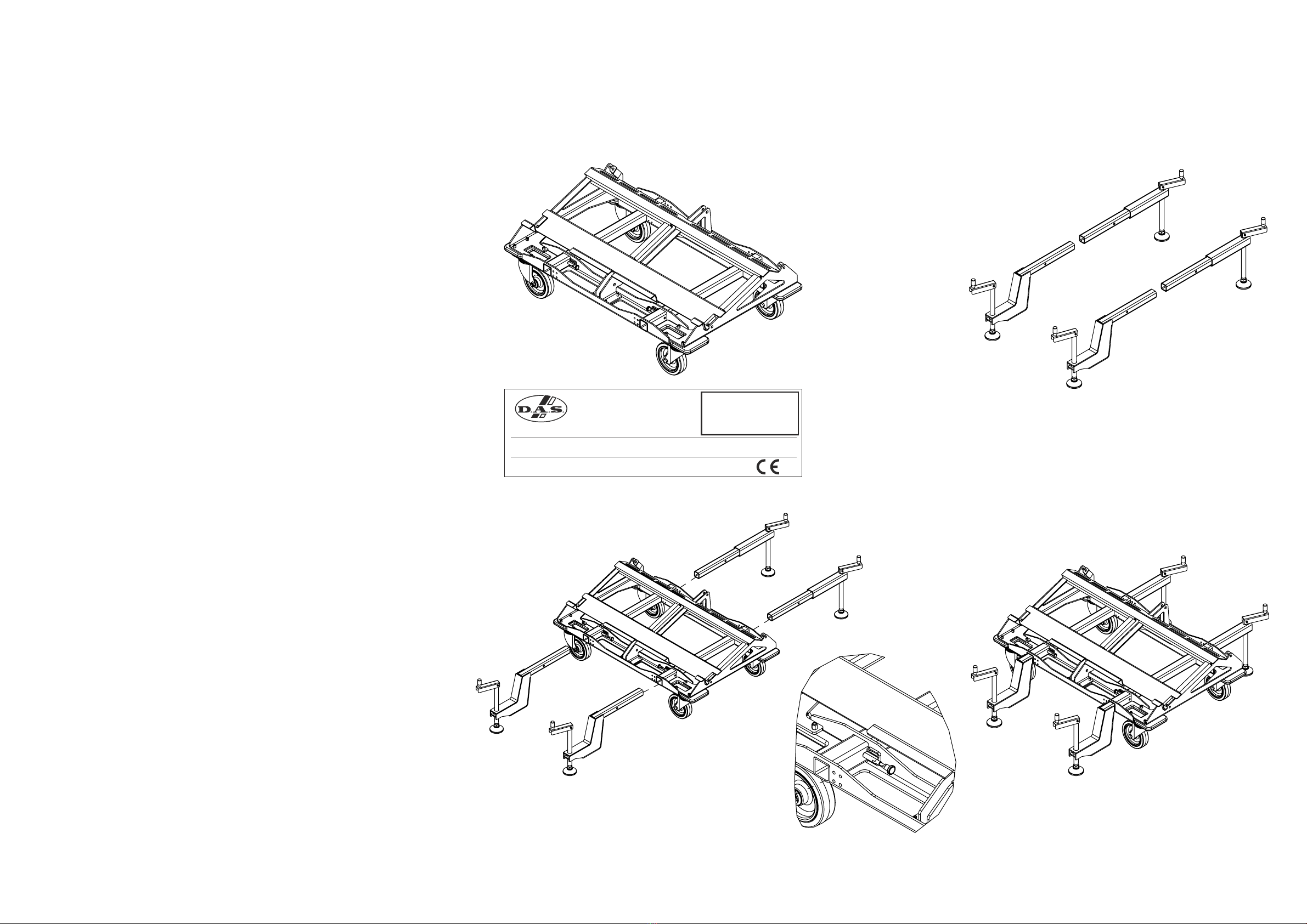
Thismanualoffersallthenecessaryinformationforying
DAS Audio systems. This document contains safety precautions
and a description of the elements to be used.
TocarryoutanyoperationsrelatedtoyingaDASAudio
system,itisrecommendedtoreadthepresentdocumentrst
and comply with the warnings and advice given. The goal is
to allow the user to become familiar with the mechanical
elements required to y the acoustic system, as well as the
safetymeasurestobetakenduringandafterassembly.
Onlyexperiencedinstallerswithadequateknowledgeof
theequipmentandlocalsafetyregulationsshouldyspeaker
boxes. It is the user´s responsibility to ensure that the systems
tobeown(includingyingaccessories)complywithstateand
localregulations.
The working load limits in this manual are the results
of tests carried out by independent laboratories. It is the
user´s responsibility to follow and comply with safety factors,
resistance values, periodical supervisions and warnings given
in this manual. Product improvement through research and
development is on going at DAS Audio, specications are
subjecttochangewithoutnotice.
It is common practice to apply 5:1 safety factors for
enclosures and static elements. For slings and elements
exposed to material fatigue due to friction and load variation
thefollowingratiosmustbemet;5:1forsteelcableslings;4:1for
steelchainslingsand7:1forpolyesterslings.Thus,anelement
withabreakingloadlimitof1000kgmaybestaticallyloaded
with200kg(5:1safetyfactor)anddynamicallyloadedwith142
kg(7:1safetyfactor).
When a system is own, the working load must be
lowerthantheresistanceofeachindividualyingpointinthe
enclosure, as well as each box.
Rigging hardware should be regularly inspected and
defectiveunitsreplaceddiscarded.Itishighlyrecommended
that you implement an equipment inspection and maintenance
program, including reports to be lled out by the inspectors.
Localregulationsmayexistthat,incaseofaccident,mayrequire
you to submit evidence of inspection reports and corrective
actions carried out after defects were found.
Absolutelynorisksshouldbetakenwithregardstopublic
safety.
When ying enclosures from the ceiling or other
structures, extreme care should be taken to assure the load
bearingcapabilitiesofthestructuressothattheinstallationis
absolutely safe. Do not y enclosures from unsafe structures.
Consult a certied professional if needed. Use gloves and all
necessaryprotectiveequipmenttoavoidpersonalinjuries.
AllyingaccessoriesthatarenotsuppliedbyDASAudio
are the user´s responsibility. Use at your own risk.

4
LARA manual / LARA - SUB
2.-Assembly of LARA unit on its transport platform.
Disassembly
Fig.1
Removethetwofrontsecuritypins
from the LARA unit and release the
connectingrods.
Gentlyplacetheunitinsertingthe
connectingrodsintothededicatedslots
of the transport platform.
Fig.2
To attach the LARA unit to the transport
platform, insert the security pins into the
front holes of the platform as shown in
thegure.
Fig.3
Now, it is time to attach the back of the
unit.
Fig.4
Removethepinthatlockstherear
connectingrod.
Lowertheconnectingrodandplace
it between the two rear plates of the
transport platform, as shown in the
gure.Attachtheconnectingrodtothe
platforminsertingthesecuritypinas
showninthegure.
Fordisassembly,proceedinreverseorder
tothatdescribedinthestepsabove.
Fig.1 Fig. 2
Fig.3 Fig.4

6
LARA manual / LARA - SUB
3.- Assembly of a LARA-SUB unit on its transport platform.
Disassembly
Fig.1
Only use the PL-LARA-SUB accessory
(WLL400kgf)showninthegureto
stack and transport up to 3 units of
LARA-SUB.
Fig.2
Place the LARA-SUB unit on the
platformaligningitsfeetwiththemarks
on the platform.
Fig.3 y 4
Notethattherstunitisnotattachedto
theplatformwithsecuritypins,however,
subsequent units need to be attached
to each other. Once a unit has been
stacked on top of another unit, insert
the security pins on both sides at the
front,asshowningure3.
Fig.5, 6 y 7
Next,removethesecuritypinfromthe
rearplates,lowertherearconnecting
rodandattachitwiththepreviously
removedsecuritypin,asshowninthe
gure.Theresultcanbeseeningure7.
*To stack a third unit, follow the same
steps
**Todisassemble,followthestepsabove
inreverseorder.
Fig.1 Fig. 2
Fig.3 y 4 Fig. 5, 6 y 7

7
LARA manual / LARA - SUB
4.- Assembly of GS-PL-LARA. Play angle settings
in LARA units. Stability, max. and min. angle and
maximum number of units
Fig.1
ThegureshowsthePL-LARA
(WLL=400kgf)accessory.
Fig.2
The GS-PL-LARA accessory can be at-
tachedtothePL-LARAtoprovideaddi-
tionalstabilityingroundstackedLARA
(WLL=400kgf)applications.
Fig.3
Thegureshowshowthedifferentparts
oftheaccessorytintothecorrespond-
ingslots,releasingthesecuritylatches
included. Note that the elbow piecess
are mounted at the front of the platform,
whiletheremainingpiecesgoatthe
back.
Fig.4
Note that the maximum number of units
thatcanbegroundstackedremains4.
PL-LARA platforms and their GS-PL-LARA
accessoryaredesignedformaximum
stabilitywitha±14°tiltabovethehorizon-
tal,regardlessofthesplayanglebetween
the4LARAunitsthatcanbestackedon
them.
WhenusingtheGS-PL-LARA,makesure
the platform and accessoryy are mount-
edonarmsurface.
PL-LARA
WORKING LOAD LIMIT
DAS Audio Group, S.L. (Valencia) Made in Spain
400Kg
MODEL: S/N:
Fig. 2
Fig. 1
Fig.3 Fig. 4

8
LARA manual / LARA - SUB
Fig.5
Asshowninthegure,thesplayangles
between two adjacent LARA units can
rangefrom0to7degreesmaximum(the
numbers on the rear plates of the LARA
unitsindicatethesplayanglesinde-
grees).
When shipped from the factory, the units
haveasecuritypinstowedinthe“PIN
HOLDER”position,insertedontheright
side of their rear plate, and another pin
stowedinthe“STORELINK”position,
insertedontheleft.Inserttherstpinin
thedesiredsplayangleandinsertthe
otherpintolocktheconnectingrodin
thechosenangleplus1.Thatis,ifthe
desiredangleis4degrees,insertthe“PIN
HOLDER”pininhole“4”andthe“STORE
LINK”pininhole“5”.Whenthedesired
angleis7degrees,insertthe“PINHOLD-
ER”pininhole“7”,andthe“STORELINK”
pinintheholemarked“7+1”.Makesure
theconnectingrodfromtheunitontop
isttedbetweentherearplatesofthe
unit below to ensure the two units are
securely attached.
4.- Assembly of GS-PL-LARA. Play angle settings
in LARA units. Stability, max. and min. angle and
maximum number of units

10
LARA manual / LARA - SUB
5.- Assembly of 4 LARA units with TOP-PL-LARA on platform
Fig.1
StacktherstLARAunitontheplatform
aspreviouslydescribedinthismanual.
Toattachthefollowingunit,removethe
top security pins of the bottom unit.
Alignthetwounitsandremovethetwo
bottom security pins of the upper unit.
Lowertheconnectingrodsandmake
suretheholesarealignedcorrectly.
Fig.2
Re-insert the four security pins to attach
the two LARA units at the front.
Fig.3
Now, it is time to attach the back of the
unit.
Fig.4
Removethesecuritypinthatlocks
therearconnectingrodandlowerthe
connectingrodfromtheupperunit.
Fig.5
Attachtheconnectingrodwiththe
securitypinandremovethesecuritypin
from the bottom unit.
Fig.6
Insertthispinintothefollowinghole
usedbytherstpin,asshowninthe
gure.
Fig.1 Fig. 2
Fig.3 Fig.4 Fig.5 Fig.6

11
LARA manual / LARA - SUB
Fig.7
Follow the same steps to stack further
units,theresultcanbeseeninthegure.
Fig.8
Rearview.
5.- Assembly of 4 LARA units with TOP-PL-LARA on platform
Fig.7 Fig. 8

12
LARA manual / LARA - SUB
Fig.9
To attach the TOP-PL-LARA to the unit on
top,rst,removethetwouppersecurity
pins from the LARA unit.
Fig.10
LowertheTOP-PL-LARA,aligntheholes
and attach with the two security pins.
Fig.11
AligntheTOP-PL-LARArearbracketwith
the last hole oin the LARA rear plate.
Fig.12
Removethesparepinstowedontherear
plates of the LARA unit and attach the
unit to the TOP-PL-LARA with it.
Fig.13
Theresultcanbeseeninthegure.
Fig.14
The stack with the accessory can be seen
inthegure.
5.- Assembly of 4 LARA units with TOP-PL-LARA on platform
Fig. 10
Fig.12
Fig.11
Fig.13 Fig.14
Fig.9

14
LARA manual / LARA - SUB
6.- Storage of platforms with TOP-PL-LARA during a show
Fig.1
Aligntheplatformwiththetopasshown
inthegure.
Fig.2
Viewfrombelow.Removethethree
securitypinsfromtheirhousing.
Fig.3
Attach the top with the security pins, as
showninthegure.
Fig.4
Thegureshowsthetwoaccessories
togetherinasingleblock.
Fig.5
Theseblockscanbepiledup,ttingthe
wheels into the slots as shown in the
gure.
Fig.6
This way, the platforms can be easily
storedunderthestagetakingupvery
little space.
Fig. 2
Fig.5
Fig.3
Fig.6
Fig.1
Fig.4

15
LARA manual / LARA - SUB
7.- AX-LARA introduction: FRAME + PICK-UP unboxing
Fig.1
The AX-LARA accessory is packed in a
woodencrate,asshowninthegure,due
toitsweight.
Fig.2
Toopenit,removethetwosecuritypins
throughthesquareopeningsinthe
crate,asshowninthegure.
Fig.3
Nowyoucanremovethelid.
Fig.4
Thegureshowsthetwopartsthat
make up the accessory: the FRAME and
thePICK-UP.
Fig.5
Attach the two parts with the pins as
shown.
Fig.6
Theresultcanbeseeninthegure.
Fig.1
Fig.3
Fig.5
Fig.2
Fig.4
Fig.6

16
LARA manual / LARA - SUB
8.- Assembly of AX-LARA on a LARA unit. Max. number of units.
LARA units AX-LARA (ying/transport mode).
Ease Focus coverage gure
Fig.1
Thegureshowshowtoattachthe
AX-LARAaccessory(WLL=2100kgf)toa
LARAunit.Todothis,removetheLARA´s
upperfrontpins,aligntheholeswiththe
accessory and attach with the same pins.
Fig.2
Theresultcanbeseeninthegure.
Fig.3
Now it is time to attach the back.
Fig.4
First,placetherearconnectingrodofthe
accessory in the slot, between the rear
plates, on the LARA.
Fig.5
RemovetheSTORELINKpinfromthe
LARAandsetitto“0”.
Fig.1
Fig.3
Fig.2
Fig.4 Fig.5

17
LARA manual / LARA - SUB
8.- Assembly of AX-LARA on a LARA unit. Max. number of
units. LARA units AX-LARA (ying/transport mode).
Ease Focus coverage gure
Fig.6
RemovethePINHOLDERpinfromthe
LARA.
Fig.7
Finally,insertthepinat“1”(=0+1)tolock
the assembly. This is the correct way to
transport the accessory on top of LARA
units stacked on their platform.
Fig.8
Now,toplacethePICK-UPinyingmode
position,removethepinthatlocksthe
PICK-UPinplace.
Fig.9
ThegureshowsthePICK-UP´sstandard
position.
Fig.10
Thisistheresult,withthePICK-UP
extendingtotheback.
Fig.6
Fig.9
Fig.8
Fig.10
Fig.7

18
LARA manual / LARA - SUB
Fig.11
Thegureshowsthetworearconnecting
rods of the accessory. One on the FRAME
andtheotheronthePICK-UP.
Fig.12
Forastandardconguration,thePICK-
UPconnectingrodisfoldedawaywitha
security pin.
Fig.13
Thegureshowshowtheaccessorywill
look in this case.
Fig.14
Thegureshowsastandard
conguration.
Fig.15
Sideviewofthesamestandard
congurationillustratingthetiltof
the system obtained with this type of
conguration.
8.- Assembly of AX-LARA on a LARA unit. Max. number of
units. LARA units AX-LARA (ying/transport mode).
Ease Focus coverage gure
Fig.14 Fig.15
Fig.13
Fig.11
Fig.12

19
LARA manual / LARA - SUB
Fig.16
To obtain the desired tilt, attach the
accessorytothesplayanglehole
indicated by the Ease Focus software. The
gureshowsthenumbersdisplayedon
thelabelofthePICK-UPaccessory.
Fig.17.
EaseFocussimulatedcoverageforthis
typeofconguration.
8.- Assembly of AX-LARA on a LARA unit. Max. number of
units. LARA units AX-LARA (ying/transport mode).
Ease Focus coverage gure
Fig.16 Fig.17
This manual suits for next models
15
Table of contents