DATA FROM SKY TrafficXRoads User manual

page 0 TrafficXRoads: Guide
TrafficXRoads: How to start
A step-by-step guide to help you get started with your
TrafficXRoads unit.

TrafficXRoads: Guide page 1
TrafficXRoads: How to start
A step by step guide to help you get started with your smart
camera.
Thank you for purchasing the TrafficXRoads and joining the FLOW family of next-gen
traffic analytic intelligence! You have purchased the most powerful and versatile traffic AI
available –it is waiting in the box to be unleashed by your creativity.
We wish you an exciting journey towards a smoother and safer traffic of tomorrow. Let
the traffic FLOW.
On behalf of the whole DataFromSky team
David Herman, CEO

page 2 TrafficXRoads: Guide
Contents
Contents ..........................................................................................................................2
Introduction .....................................................................................................................3
Quick start ...................................................................................................................... 4
Front panel.......................................................................................................................5
Rear panel ....................................................................................................................... 6
Carrier Board ....................................................................................................................7
Mounting......................................................................................................................... 8
System web interface and network settings ..................................................................10
FLOW –connect and define traffic analytics...................................................................14
Detection of traffic events .............................................................................................18
Reducing latency............................................................................................................31
More about FLOW framework........................................................................................35
Conclusion .....................................................................................................................37
Technical specification...................................................................................................38
Document version: 20221103

TrafficXRoads: Guide page 3
Introduction
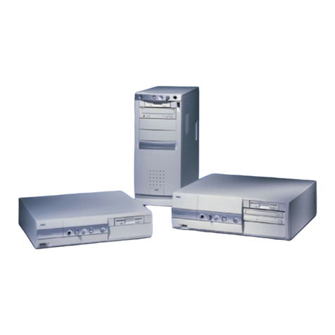
TrafficXRoads unit is a video analytics embedded computer designed for real-time
detection tasks for dynamic control of traffic light signalling and the collection of traffic
data from IP cameras. It has an industrial NVIDIA processor, the Jetson NX that runs the
AI-based detection and tracking algorithm which turns any video stream into high quality
trajectory data about each road user. The system is powerful enough to analyse data from
up to 6 connected cameras in real-time with an operating range of more than 80 meters.
The highly optimized and fully configurable trajectory processing engine is able to
evaluate dozens of detection tasks in each camera view in parallel.
Product applications:
Traffic monitoring and control
Traffic data collection
Parking management
Security

page 4 TrafficXRoads: Guide
Quick start
For start you need to connect:
-12- 24V DC power source
ominimum 65W (100W recommended)
ored and yellow +
oblack -
-Modem / your computer (LAN/WAN)
-IP Camera (PoE Ports)
On your computer:
-Find IP of your TrafficXRoad
oDevice default IP is 192.168.50.10
oIn case of DHCP server you can search IP via MAC address that is on the top
side of device
-Login to web-admin console on the device on https:\\deviceIP:8000
(https://192.168.50.10:8000) and configure as needed
Default login is “admin” and password is “admin01”
-Start your FLOW and click on Traffic survey or FLOW device live stream tile on the
launch screen
-Connect via IP address
oDefault login is “admin” and password is “admin”
-Add cameras, interfaces and configure the analytics

TrafficXRoads: Guide page 5
Front panel
No.
Name
Description
1
SSD Key Lock
Lock and unlock the SSD tray (see 2.3 SSD Installation).
2
SD Card Slot
Insert a SD card to the card slot.
3
SIM Card Slot
Insert a SIM card to the card slot.
4
LAN/WAN
One 10/100/1000 Base-Tx Ethernet ports for connecting to the
network
5
IR
This function is currently reserved.
6
LED Indicator
HDD: HDD LED indicator.
Fail: System Fail LED indicator.
7
PoE Ports
PoE ports (10/100 MbE, total 75W) for connecting to the IP cameras
or other PoE devices.
8
USB2.0 USB2.0
port.
USB2.0 port.
9
Power Indicator
Power LED indicator.

page 6 TrafficXRoads: Guide
Rear panel
No.
Name
Description
1
Audio Input
Connects to audio input devices, such as microphones. Note that the
microphones with a (built-in) amplifier and external power supply are
required.
2
Antenna
Connects the antenna to the AI mobile NVR for 3G / 4G / WiFi / GPS
functions
3
VGA Port
This port is currently reserved.
4
Audio Output
Connects to an audio output device, such as speakers. Note that the
speakers with a (built-in) amplifier and external power supply are
required.
5
USB3.0
USB3.0 port.
6
HDMI Port
HDMI display output.
7
RS-232 Port
COM port for RS-232.
8
RS-485 Port
COM port for RS-485.
9
Alarm IO
Provides 4 alarm inputs and 4 alarm outputs.
10
DC Power Input
Connecting to the power source

TrafficXRoads: Guide page 7
Carrier Board
Main board
Power Board
IO Board
No.
Name
No.
Name
1
Console
12
Audio In
2
VGA
13
USB 3.0
3
HDDD Thermal Sensor
14
HDMI
4
HDD Heater (Reserved)
15
RS232
5
HDD Power
16
RS485
6
Video In / Camera Power
17
Alarm IO (4-input, 4.output)
7
SATA Port x 2
18
Power In
8
10/100 Ethernet PoE Port x 8
19
SIM Card slot
9
USB Port
20
SD Card slot
10
OTG
21
3G, 4G
11
Audio Out
22
GPS
Dimensions (W x D x H)
Main Board: 170 x 179.3 x 35 mm / 6.7" x 7.1" x 1.38"
Power Board: 30.1 x 98 x 25 mm / 1.19" x 3.85" x 0.98"
IO Board: 45 x 98.3 x 18 mm / 1.77" x 3.87" x 0.71"

page 8 TrafficXRoads: Guide
Mounting
TrafficXRoad is possible to screw it via L –bar or attach on DIN rails.
Conection via screw
Conection via DIN rails

TrafficXRoads: Guide page 9
Field installation
Power source
TrafficXRoads is powered by 12-24 DC power source. Unload device needs minimum 65W
and every camera you connect use 5W –15W extra power. We recommend you 100W
power source.
Device is powered by 3 wires:
-Red (positive DC pole)
-Black (negative DC pole)
-Yellow (for turning on/off)
Yellow cable must be connected with red cable. The
easiest way to do it is by WAGO clamp or
double bootlace ferrule.
Connection
Connect TrafficXRoads to your computer or modem via LAN/WLAN
Connect up to 6 IP cameras via PoE ports (1-8). Beware of limiting the maximum power
to 75 W.

page 10 TrafficXRoads: Guide
System web interface and network settings
TrafficXRoads unit can be deployed in different scenarios and with different network
setups.
The web administration interface allows you to configure network settings, VPN and do
the reboot or factory reset of the unit. By default, the unit has static IP address
192.168.50.10 and the web administration interface can be accessed using the URL:
https://192.168.50.10:8000 . To sign in, use the following default login credentials:
login: admin
password: admin01
To be able to access to the web administration interface, your computer must
be in the same network. Setup the appropriate IP address and subnet mask at
your computer (for example 192.168.50.2/24 i.e. mask is 255.255.255.0).
All the configurations relating to this video analytic system are done using the
FLOW interface, the desktop application FLOW Insights. To connect to the
server, you need to know its IP address.

TrafficXRoads: Guide page 11
System settings
After a successful login to the web console, the first tab that you see is the System tab.
On this tab, you can change the name of the unit, do a reboot, backup settings of the web
console or restore them if needed. It is possible to do “factory reset” here and restore the
web console settings into the default state (including default IP address, names and
passwords).
Network settings
The set-up of the Ethernet interfaces is done in the Network tab. The unit has two physical
Ethernet interfaces but both of them are under the same address (address bonding). In
the web interface, the Ethernet interface is under the name bond0. In the top part of the
tab you can see the chosen interface and its current state –whether the interface is
enabled in the system and whether it is connected.
For the Ethernet Interface you can enable/disable the loading of IP address from the DHCP
server and set up individual static IP addresses (up to 4) and DNS servers (up to 3).
We recommend using static IP addresses in real world deployments.

page 12 TrafficXRoads: Guide
Virtual private networks
The unit has multiple preconfigured VPNs. These include a system service VPN using
which the manufacturer can remotely access the unit. This VPN can be deactivated if
needed. For the service VPN to work this VPN must be active, the unit must be connected
to the internet and port 31228 UDP must be enabled (VPN connection to DataFromSky
service VPN on 172.105.65.31).
The unit also has a Wireguad or OpenVPN client VPN network. These VPN networks can
be configured by the user as needed. The configuration for both VPN networks is done by
uploading a text configuration file according to the requirements of the specific VPN.

TrafficXRoads: Guide page 13

page 14 TrafficXRoads: Guide
FLOW –connect and define traffic analytics
FLOW is an AI-based traffic video-analytical engine that runs on the unit. To configure
various traffic tasks on the unit you need the FLOW Insights application which can be
downloaded here: https://datafromsky.com/flow-versions/ There you should choose the
correct version of FLOW Insights to match the version of the FLOW running on the
TrafficXRoads device.
If you have the latest version of FLOW installed on your device, you can get the latest
FLOW Insights version here:
http://www.datafromsky.com/download/flow/demokit/FLOW_Demokit.exe
How to connect to the unit with FLOW Insights
First, download the FLOW Insights desktop application and install it on your computer. It
needs to be a 64-bit Windows operating system or Linux system (contact us for the Linux
version). The device must be network accessible from your PC and you need to know its
IP address (see the Network configuration section).
Launch FLOW Insights on your PC. Click on start FLOW in the third window on the bottom
left named “Traffic survey or FLOW device live stream”. In the first field, enter the unit´s
IP address in the format xx.xx.xx.xx. Leave the second field empty and hit enter.

TrafficXRoads: Guide page 15
On the next screen, log in with the following credentials:
Login: admin
Password: admin
Note that you should change this password when you log into FLOW
insights in the user settings section.
How to add the camera streams / analytics
We are now communicating with the TrafficXRoads unit and you can start configuring it.
First, we need to add a source camera stream.

page 16 TrafficXRoads: Guide
The camera video source stream address and optional OnVIF source address are
formatted in the following way:
●Video source: rtsp://user:password@ip:port/path/file
●OnVIF source: user:password@ip
The required information is camera specific and can be usually found in the camera user
manual or at the web interface of the IP camera. The camera must be network accessible
from the unit.
After you have filled out the dialog window and you click on the Create button the camera
stream will be registered. The unit will then keep trying to establish connection with the
camera. If the stream is opened, you will see a live preview image in the status panel of
the camera and the status will change to Running. If the stream does not open, the status
panel will signal an error in connection with the camera.
Unable to establish connection with the camera? Check whether the
camera is network accessible from the unit. Also make sure that that
the entered RTSP address is correct.
You can connect the other camera streams that you want to analyze with the particular
TrafficXRoads unit the same way.
Maximum number of camera streams
The unit is capable to process a certain number of FPS based on the provided/selected
video analytics engine.

TrafficXRoads: Guide page 17
FLOW distributes the processing power evenly between the analytics. If the sum of FPS
from the different camera streams is bigger than the processing power capacity of the
processing unit with the particular video analytics engine, then incoming image frames
start to get dumped. If this would happen it does not necessarily mean that the traffic
statistic would be negatively affected. This means the results would not be affected in
case the evaluation FPS on the camera stream would be sufficient in regards to the
specific monitored traffic scene. This would also hold true if the time interval between the
evaluated image frames would be of such length, that the objects don’t move by more
than their “size” in the image. In case these conditions would not be met, the tracker
might fail in connecting the detections because they would be too far away from the last
detected position of the object in the image.
The maximum number of camera streams can be limited with a license. After
reaching this number of streams, the unit will not allow you to add any
additional camera streams.
Type of monitored environment and recommended minimum detection FPS
Pedestrian movements –sidewalk, town square, bus stop (up to 7 km/h): 5 FPS
Pedestrian and cyclist movements –bicycle path (up to 50 km/h): 10 FPS
Traffic junction, city traffic (up to 75 km/h): 15 FPS
Monitoring of district level road - (up to 150 km/h): 20 FPS
Highway/motorway monitoring - (up to 200 km/h): 25 FPS
PTZ cameras with the ONVIF protocol support
FLOW framework has implemented PTZ camera support for cameras with the ONVIF S
protocol. Thanks to this, you can define traffic analytics for the different PTZ camera
positions. These analytics are then active only when the camera is in the defined position,
otherwise they are inactive. In FLOW you can then create different analytical scenarios
tied to the different PTZ camera views/positions from a single PTZ camera.
If the PTZ camera has the ONVIF protocol,
you can easily define the ONVIF address in
the dialog for adding cameras. Next you
need to go to the Analytics settings and set
Camera home position including some
movement tolerance in the Camera settings
section. When the camera is in this position,
the analytic will be running. In the moment
when the camera leaves this position, no
more trajectories will be received but the
analytical engine will keep running. This

page 18 TrafficXRoads: Guide
means that all the expression, defined time modes etc… will keep being processed.
FLOW does not directly control the cameras but instead acts as a passive
receiver of the camera position and zoom information. Based on this
information the different analytics get activated to analyze the newly incoming
trajectories.
Detection of traffic events
The FLOW framework enables you to define detections of very complex traffic events
including interactions between objects. The generic FLOW description can be found here
(https://intercom.help/datafromsky/en/collections/2019942-flow-real-time-
monitoring), including different tutorials. In this document we will focus only on the
selected basic tasks that can be used in detection systems for traffic control. The
Definition of detection of traffic events is done in the Definition tab.

TrafficXRoads: Guide page 19
Basic object presence detection
For the detection of object presence in real-time we can use the combination of Zone
spatial filter in the NOW time mode. The Zone spatial filter can be combined with the
Category filter, if you want to react to a presence of a specific object type. The number of
detectors is not limited in the system. On the left side, pick the Create zones/gates tool
and draw a zone in the area where we want to detect the vehicle presence. The system
will automatically recognize whether it is a gate or a zone based on the drawn shape.
Next, we move the zone with the drag and drop technique into the right side panel, also
referred to as workspace, which will instantiate it and the zone will start automatically
filtering the trajectories from within the FLOW device cache.
Table of contents
