BAC 3000 Series User manual

RIGGING & ASSEMBLY INSTRUCTIONS
Series 3000 Cooling Tower
Series 3000

Series 3000 Cooling Towers should be rigged and
assembled as outlined in this bulletin.
These procedures should be thoroughly reviewed prior to the
actual rigging and assembly of the equipment to acquaint all
personnel with procedures to be followed and to assure that all
necessary equipment will be available beforehand.
Be sure to have a copy of the certified drawing available for reference. If
you do not have a copy of this drawing, or if you need additional information
about this unit, contact your local BAC Representative whose name and
telephone number are on a label adjacent to the access door. The model
number and serial number of the unit are also located in this area.

WWW.BALTIMOREAIRCOIL.COM
1
Table of Contents
RIGGING & ASSEMBLY INSTRUCTIONS » SERIES 3000 COOLING TOWER
1Introduction
2Safety
2Shipping
2Pre-Rigging Checks
3Unit Weights
3Anchoring
3Cold Weather Operation
3Location
3Warranties
3Unit Operation
2Unit Rigging & Assembly
4Rigging
5Single-Cell Installation
5Two Piece Section Assembly
6Multi-Cell Installation
6Multi-Cell Unit Assembly
6Flume Box Installation
8Optional Positive Closure Plate Installation
9Fan Guard Installation
9One-Piece Fan Guard
10 Two-Piece Fan Guard
11 Four-Piece Fan Guard
13 Top Inlet Piping Installation
15 Motor Location and Conduit Installation
3Optional Accessory Installation
17 ENDURADRIVE™ Fan System Installation
18 Whisper Quiet Fan Installation
20 Side Outlet Depressed Sump Box Installation
21 Factory Pre-Wired Terminal Box
21 Optional Accessories and Equipment

WWW.BALTIMOREAIRCOIL.COM
2
Safety
Adequate precautions appropriate for the installation and location of these products should
be taken to safeguard the equipment and the premises from damage and the public from
possible injury. The procedures in this manual must be thoroughly reviewed prior to rigging
and assembly. Read all dangers, warnings, cautions, and notes detailed in the margins.
When the fan speed of the unit is to be changed from the factory set speed, including the
use of a variable speed device, steps must be taken to avoid operating at or near the fan’s
“critical speed” which could result in fan failure and possible injury or damage. Consult
with your local BAC Representative on any such applications.
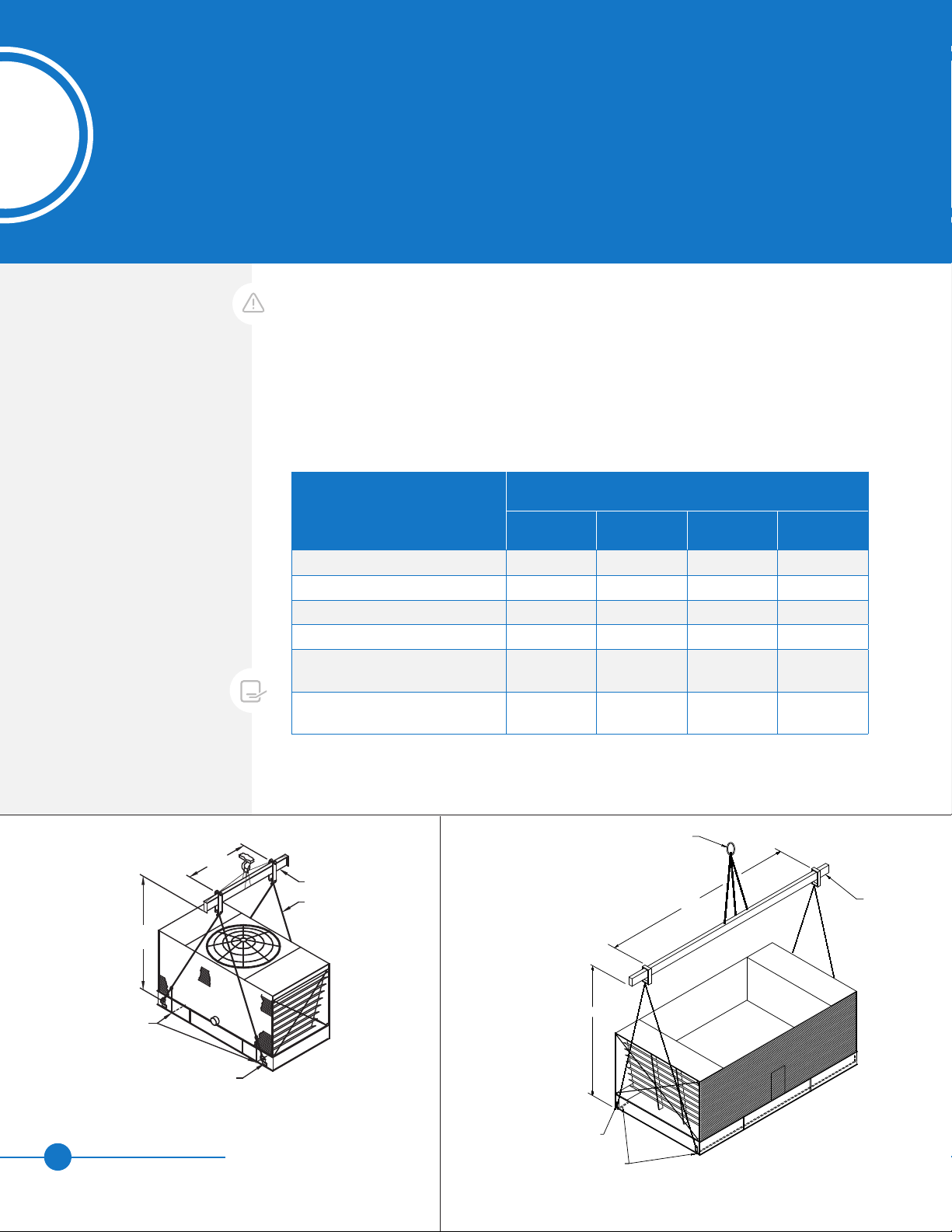
Shipping
BAC Cooling Towers are factory assembled to assure uniform quality and minimum field
assembly. Models S3E/XES3E-8518-xxx, S3E/XES3E-1020-xxx, S3E/XES3E-1222-06x,
S3E/XES3E-1222-07x, and S3E/XES3E-1424-07x ship in one section ship in one section.
Models S3E/XES3E-1222-10x through S3E/XES3E-1222-14x and S3E/XES3E-1424-12x
through S3E/XES3E-1424-14x ship in two sections. For the dimensions and weights of a
specific unit or section, refer to the certified drawings.
Pre-Rigging Checks
When the unit is delivered to the jobsite, it should be checked thoroughly to ensure all
required items have been received and are free of any shipping damage prior to signing the
bill of lading.
The following parts should be inspected:
Sheaves and Belts / Gearbox
Bearings
Bearing Supports
Fan Motor(s)
Fan(s) and Fan Shaft(s)
Float Valve Assembly(s)
Water Distribution System
Fill
Cold Water Basin Accessories
Interior Surfaces
Exterior Surfaces
Optional EASY CONNECT®Piping
Arrangement (when provided)
Louvers / Combined Inlet Shields
Optional Air Inlet Screens
(when provided)
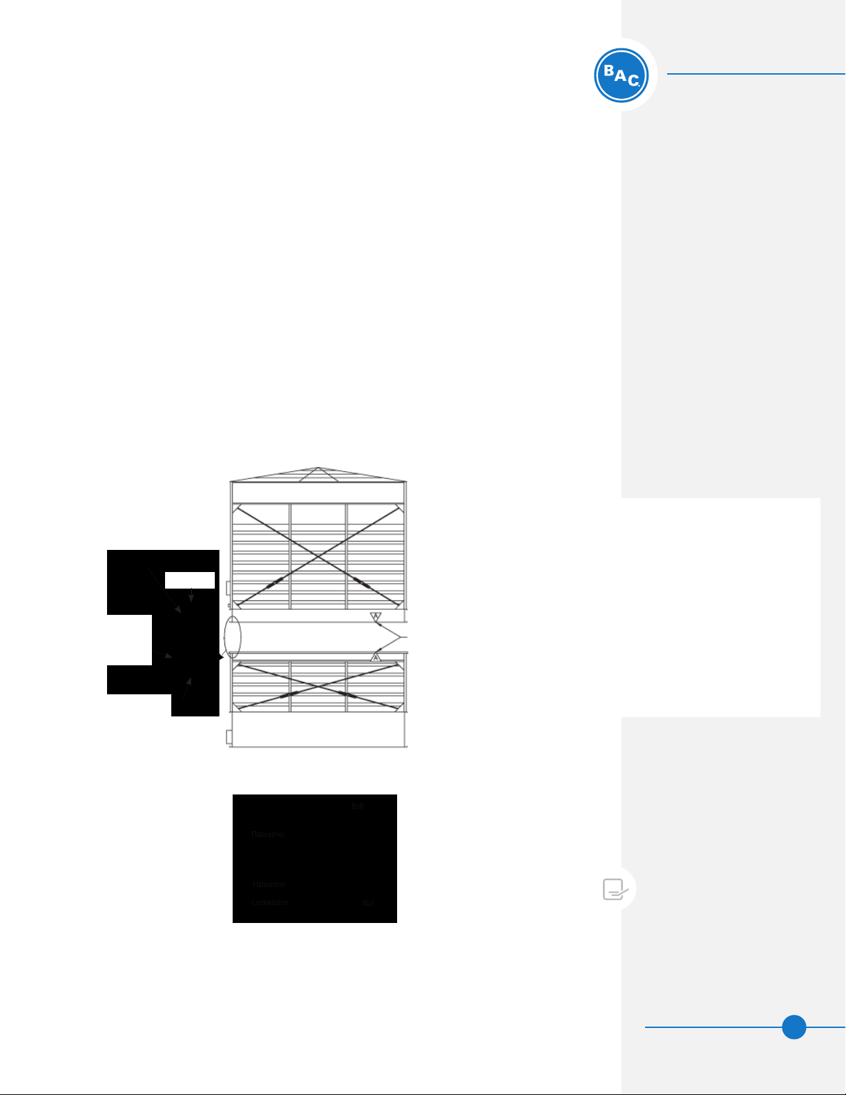
Mating Surfaces Between Sections /
Modules
Miscellaneous Items: All bolts, nuts,
washers, and sealer tape required to
assemble sections or component parts
are furnished by BAC and shipped
with the unit. A checklist inside
the envelope marked “Customer
Information Packet” indicates what
miscellaneous parts are included
with the shipment and where they are
packed. This envelope will be attached
to the side of the unit or located in a
box inside the unit.
SERIES 3000 COOLING TOWER
Introduction
1
WARNING: Failure to use lifting
provisions can result in a dropped
load causing severe injury, death,
and/or property damage. Lifts
must be performed by qualified
riggers following BAC published
Rigging Instructions, and generally
accepted lifting practices. The
use of a supplemental safety
sling may also be required if the
lift circumstances warrant its
use, as determined by the rigging
contractor.
CAUTION: Only personnel qualified
to do so should undertake
operation, maintenance and repair
of this equipment. Proper care,
procedures and tools must be used
in handling, lifting, installing,
operating, maintaining and
repairing this equipment to prevent
personal injury and/or property
damage.

WWW.BALTIMOREAIRCOIL.COM
3
SERIES 3000 COOLING TOWER
Introduction
Unit Weights
Before rigging any unit, the weight of each section should be verified from the unit
certified drawing. Some accessories add additional weight as shown on the respective
accessory drawings.
Anchoring
Seven-eighths (7/8”) diameter holes are provided in the bottom flange of the basin section
for bolting the unit to the support beams. Refer to the suggested support location drawing
included in the submittal for location and quantity of the mounting holes. The unit must
be level for proper operation. Anchor bolts must be provided by others. The IBC rating is
only certified with standard anchorage locations. Using alternate anchorage locations or
alternate steel supports will void any IBC wind or seismic ratings. Contact your local BAC
Representative for details
Cold Weather Operation
These products must be protected by mechanical and operational methods against damage
and/or reduced effectiveness due to possible freeze-up. Please refer to the Series 3000
Operation & Maintenance Manual on www.BaltimoreAircoil.com, or contact your local BAC
Representative for recommended cold weather operation strategies.
Location
All evaporative cooling equipment must be located to ensure an adequate supply of fresh
air to the unit air intakes. When units are located adjacent to walls or in enclosures,
care must be taken to ensure the warm, saturated, discharge air is not deflected and
recirculated back to the air intakes.
Each unit should be located and positioned to prevent the introduction of discharge
air into the ventilation system of any building. For detailed recommendations on BAC
equipment layout, see our website at www.BaltimoreAircoil.com or contact your local
Representative.
Warranties
Please refer to the Limitation of Warranties (located in the submittal package) applicable
to and in effect at the time of the sale/purchase of these products.
Unit Operation
Prior to start-up and unit operation, refer to the Series 3000 Operation & Maintenance
Manual shipped with the unit and also available at www.BaltimoreAircoil.com.
NOTE: Each unit must be located
and positioned to prevent the
introduction of discharge air
into the ventilation systems of
the building on which the unit is
located and of adjacent buildings.
ATTENTION: Before an actual lift
is undertaken, ensure no water,
snow, ice, or debris has collected
in the basin or elsewhere in the
unit. Such accumulations will add
substantially to the equipment’s
lifting weight.
Introduction
Safety
Shipping
Pre-Rigging Checks
Unit Weights
Anchoring
Cold Weather Operation
Location
Warranties
Unit Operation

WWW.BALTIMOREAIRCOIL.COM
4
Rigging
Refer to Table 1 and Figures 1 and 2 for the required minimum spreader bar and the
recommended vertical dimension “H” from the lifting device at the base of each unit or
section to the spreader bar.
All single cell and multi cell units must be rigged one section at a time. Models
S3E/XES3E-8518-x, 1020-x, 1222-06x, 1222-07x, and 1424-07x ship in one section
per cell. All other models ship in two sections per cell.
Model Number
Dimensions (For Each Section)
Section Min. H Min. W1 Min W2
S3E/XES3E-8518-x One Section 15' 8'-6" 18'-1"
S3E/XES3E-1020-x One Section 17' 10' 20'-1"
S3E/XES3E-1222-06x, 1222-07x One Section 18' 12' 21'-7"
S3E/XES3E-1424-07x One Section 20' 14' 24'-1"
S3E/XES3E-1222-10x through
S3E/XES3E-1222-14x Upper/Lower 18'/18' 12'/12' 21’-7”/21’-7”
S3E/XES3E-1424-12x through
S3E/XES3E-1424-14x Upper/Lower 20'/20' 14'/14’ 24’-1”/24’-1”
H
S
PREADER
B
AR
(Min.)
W1
Lifting Cable
Safety
Slings
Lifting Device For
This Section Only
(Min.)
W1
Spreader Bar
Lifting Cable
H
Lifting Device For
This Section Only
Do Not Use For
Final Positioning Of
Assembled Cell
Spreader Bar
Lower
Section
Safety
Slings
Lifting Device Location
Must be Used for
Final Positioning of
Multi-Cells
Spreader Bar
(Min.)
W2
H
Safety Slings
Lifting Device
Lifting Rig
Lower
Section
Shown
For multi-cell units,
the lifting devices may
be relocated as shown
in this figure on lower
sections only. Contact
your local BAC
Representative
for upper section
lifting options.
Figure 1. Lifting Instruction for Single-Cell Units:
One Section Cells or Two Section Cells (Upper Section Shown)
Figure 2. Lifting Instruction for Multi Cell Units:
One Section Cells or Two Section Cells (Lower Section Shown)
Table 1. Minimum Vertical Dimension and Spreader Bar Length
SERIES 3000 COOLING TOWER
Unit Rigging & Assembly
2
NOTE: For weight information refer to
the submittal drawing package.
WARNING: Failure to use lifting
provisions can result in a dropped
load causing severe injury, death,
and/or property damage. Lifts
must be performed by qualified
riggers following BAC published
Rigging Instructions, and generally
accepted lifting practices. The
use of a supplemental safety
sling may also be required if the
lift circumstances warrant its
use, as determined by the rigging
contractor.

WWW.BALTIMOREAIRCOIL.COM
5
Unit Rigging & Assembly
Rigging
Single-Cell Installation
Two Piece Section Assembly
Single-Cell Installation
Two Piece Section Assembly
1. Remove any accessories shipped in the cold water basin.
2. Position the lower section on the unit supports and bolt in place.
3. Wipe any moisture and dirt from the perimeter mating flanges of the lower
section.
4. Install foam seal tape (BAC part # 270175) supplied with the unit, as
illustrated in Figure 3, on the mating flanges of the lower section in a
continuous line. At each corner, allow 1” overlap.
5. Complete assembly using the external bolt holes as guides for alignment:
–Before lowering the upper section onto the lower section, be sure to line
up the bolt holes using drift pins as illustrated in Figure 5, no fewer than
one hole at each edge. Guide the upper section onto the lower section
starting with a bolt hole at one corner and following down the flange.
–Match marks must line up as shown in Figure 3.
–Secure the upper section in place as shown in Figure 4 to ensure leak-
free operation.
Figure 5. Drift Pin Alignment
Figure 4. Typical Bolting
NOTE: 1/2” bolts, flat washers, and
lock washers are used.
Foam Seal
Tape
Flat Washer,
Lock Washer,
and Nut
1/2” Bolt
1/2”
Flat
Washer
Match Marks
Figure 3. Upper and Lower Assembly for Series 3000 Cooling Towers

WWW.BALTIMOREAIRCOIL.COM
6
Multi-Cell Installation
Refer to the submittal drawings for the proper orientation of each cell. The number and
“face” are stenciled on the outer basin wall. Multi-cell cooling tower installations may
employ flume boxes to equalize the water level in the basin of each cell. Follow directions
in “Flume Box Installation” for details on their installation.
Multi-Cell Unit Assembly
1. First, position the lower section of all cells on the unit supports and bolt in place.
Some units come furnished with a flume box. If they do, use the flume box assembly
procedure outlined in “Flume Box Installation” to connect the basins of the multi-cell
units.
2. Wipe any moisture and dirt from the perimeter mating flanges.
3. Install foam seal tape (BAC part # 270175) supplied with the unit, as illustrated in
Figure 3, on page 5 on the mating flanges of the lower sections in a continuous line.
At each corner, allow 1” overlap.
4. Complete assembly using the internal drift pin alignment guides:
–Using drift pins in the drift pin guides provided (Figure 7), guide the top section on
to the bottom section.
–Match marks must line up as shown in Figure 3 on page 5.
–Bolt the top sections onto the bottom sections as shown in Figure 4 on page 5 using
the bolting channels in Figure 6.
Flume Box Installation
1. Position Cell #1 on the unit support and bolt in place.
2. Wipe down the surface adjacent to the flume opening of Cell #1 to remove any dirt or
moisture that may have accumulated during shipment.
3. Wipe down the flanges on both ends of the flume box. On one end, apply a layer of
flat butyl sealer tape (BAC part # 554000) around the face of the flange over the
centerline of the holes. Do not overlap or stretch too thinly at the corners. When it is
necessary to splice the sealer tape, be sure to press the two ends together to form a
smooth, continuous strip. Apply a second layer of flat butyl sealer tape over the first
layer following the same procedure. Refer to Figure 8, Detail A.
4. Using drift pins to align the bolt holes, place the flume box over the opening in the
basin of Cell #1.
5. Fasten into place as shown in Figure 9. For basins with TriArmor®Corrosion Protection
System, backing plates are to be installed inside the basin and flume box opening (see
Figure 10, Detail A). Insert the 3/8” self-tapping screws or bolts in each hole from the
flume box into the basin wall and backing strips (if applicable) as illustrated in Figure
10.
NOTE: Flume boxes furnished
with units constructed with
TriArmor®Corrosion Protection
System or stainless steel basins
are assembled with stainless
steel bolts, washers and nuts
in lieu of self tapping screws.
Before installing the nuts, apply a
lubricant to the bolts to reduce the
potential for seizing.
Figure 6. Upper and Lower Assembly - Drift Pin Guides
Drift Pin Guides
Figure 7. Bolting Channels
Bolting Channels

WWW.BALTIMOREAIRCOIL.COM
7
Unit Rigging & Assembly
Multi-Cell Installation
Multi-Cell Unit Assembly
Flume Box Installation
Cell #1
Cell #2
Figure 8. Flume Box Installation
2 Layers Of Flat
Sealer Tape
Apply Flat Sealer Tape
Over The Center Line
of the Bolt Holes
Detail A
NOTE: For cold water basins
constructed with the TriArmor®
Corrosion Protection System, attach
the vertical and horizontal backing
plates as shown in Figure 10,
Detail A.
2 Layers of Flat
Butyl Sealer Tape
A
A
Cell #1
Cell #2
3/8" S.T. Screw
2 Layers of Flat
Butyl Sealer Tape
Flume Box
Cell #1 Cell #2
2 Layers of Flat
Butyl Sealer Tape
Figure 9. Expanded View
Figure 10. Elevation View
2 Layers of Flat
Butyl Sealer Tape
A
A
Cell #1
Cell #2
3/8" S.T. Screw
2 Layers of Flat
Butyl Sealer Tape
Flume Box
Cell #1 Cell #2
2 Layers of Flat
Butyl Sealer Tape
2 Layers of Flat
Butyl Sealer
Tape
SST 3/8 X 1/4
Bolt (Typ.)
Flume Box
Backing Plates Used on
TriArmor® Basins Only
SST 3/8
Flatwasher (Typ.)
No Sealer Between
Backing Plates
and Basin Wall Basin Wall
Detail A. For Units with TriArmor®
Corrosion Protection System Only
6. Apply two layers of flat butyl sealer tape to the other end of the flume box.
7. Wipe down the surface adjacent to the flume opening of Cell #2 to remove any
dirt or moisture. Position Cell #2 on the unit supports.
8. Using drift pins to assure alignment, draw Cell #2 tight against the flume box.
9. Repeat Step 5 to fasten the flume box to Cell #2.

WWW.BALTIMOREAIRCOIL.COM
8
Positive Closure Plate Installation
The optional positive closure plate and gasket can be furnished on multi-cell units to allow
individual cells to be isolated for cleaning and routine maintenance. The plate ships loose
inside the cold water basin.
1. Remove nuts and flat washer from the flume box.
2. Position the neoprene gasket and positive closure plate over the bolts and fasten in
place with 3/8” wing nut and flat washers.
3. When the cooling tower operation does not require use of the positive closure plate,
remove the closure plate and gasket. Retighten the flume box using the wing nuts and
flat washers.
2 Layers of Flat
Butyl Sealer Tape
B
B
Cell #1
Cell #2
Neoprene
Gasket
Positive
Closure Plate
3/8" Flatwasher
3/8" Wing Nut
2 Layers of Flat
Butyl Sealer Tape 3/8" S.T.Screw
3/8" Self
Cutting Bolt
Neoprene Gasket
Positive Closure Plate
Flume Box
Cell #1 Cell #2
2 Layers of Flat
Butyl Sealer Tape
2 Layers of Flat
Butyl Sealer Tape
B
B
Cell #1
Cell #2
Neoprene
Gasket
Positive
Closure Plate
3/8" Flatwasher
3/8" Wing Nut
2 Layers of Flat
Butyl Sealer Tape 3/8" S.T.Screw
3/8" Self
Cutting Bolt
Neoprene Gasket
Positive Closure Plate
Flume Box
Cell #1 Cell #2
2 Layers of Flat
Butyl Sealer Tape
Figure 11. Expanded View
Figure 12. Elevation View

WWW.BALTIMOREAIRCOIL.COM
9
Unit Rigging & Assembly
Multi-Cell Installation
Optional Positive Closure Plate
Fan Guard Installation
One-Piece Fan Guard
Fan Guard Installation
Due to height limitations on truck shipments, the fan guard may ship unmounted. Never
step or walk on the fan guard when installed. Refer to Table 2 for the number of fan guard
pieces Series 3000 Cooling Towers will have .
DANGER: Fan guard must be
securely in place before the cooling
tower is placed in operation. Never
step or walk on the fan guard.
Failure to follow these instructions
may result in serious injury or
death.
NOTE:
1. Existing 3/8” stud and nut for
guard mounting at fan deck
level (3/8” x 1 1/2” bolt for
guards mounted on top of cowl
extensions).
Figure 13. One-Piece Fan Guard Assembly
See Detail A
Detail A
Fan Guard Clip
3/8" Locknut
Fan Guard
Model Number
Number of Fan
Guard Pieces
S3E/XES3E-8518-xxx 1
S3E/XES3E-1020-xxx, 1222-xxx, 1424-07x 2
S3E/XES3E-1424-12x, 1424-13x, 1424-14x 4
Table 2. Number of Fan Guard Pieces
One-Piece Fan Guard
Mount fan guard to unit as illustrated in Figure 13, Detail A.

WWW.BALTIMOREAIRCOIL.COM
10
See Detail C
(All Except Seam)
See Detail A
(At Seam Only)
See Detail B
See Detail B
X
Y
Y
X
Figure 14. Two-Piece Fan Guard Assembly
Fan Diameter X Y
9’ 10” 17”
10’ 10” 20”
11’ 10” 23”
Table 3. -U-Bolt Location Dimensions for Two-Piece Fan Guard Fastening
Fan Guard
U-Bolt Assembly
Fan Guard Clip
3/8" Locknut
Fan Guard
Detail A Detail B Detail C
NOTE: For guards mounted at
fan deck level, fasten the guard
perimeter to existing 3/8” threaded
studs protruding up from fan deck.
For guards mounted to the top
of fan cowl extension(s), fasten
the guard perimeter using 3/8” x
1-1/2” long bolts supplied with fan
guard hardware.
Two-Piece Fan Guard
1. Using six U-bolt assemblies, fasten the two halves of the fan guard together as
illustrated in Figure 14, Detail B. Locate the U-bolt assemblies along the seam
between the two guard halves per the X and Y dimension provided in Table 3, which
are based on the diameter of the supplied fan.
2. Gradually tighten both nuts of the U-bolt assembly, alternating from one to the other,
until 20-25 ft-lb of torque is achieved.
3. Mount the fan guard to the unit as illustrated in Figure 14, Detail A for the ends of
the seam where the two guard halves join together, and Detail C for all other locations
around the fan guard perimeter.
DANGER: Fan guard must be
securely in place before the cooling
tower is placed in operation. Never
step or walk on fan guard. Failure to
follow these instructions may result
in serious injury or death.
3/8" Locknut
Fan Guard
Fan Guard Clip

WWW.BALTIMOREAIRCOIL.COM
11
Unit Rigging & Assembly
Fan Guard Installation
Two-Piece Fan Guard
Four-Piece Fan Guard
Fan Guard
Support Fan Guard
Support
3/8" x 1" Bolt
3/8" Flatwasher
3/8" Flatwasher
3/8" Locknut
Fan Guard Plate
Fan Guard Clip
3/8" Locknut
Fan Guard
Detail A Detail B Detail C
See Detail C
See Detail A For
Fastening the Fan Guard
to the Fan Screen Support
See Detail B
Figure 15. Four-Piece Fan Guard Assembly
DANGER: Fan guard must be
securely in place before the cooling
tower is placed in operation. Never
step or walk on the fan guard.
Failure to follow these instructions
may result in serious injury or
death.
Four-Piece Fan Guard
1. Assemble fan guard supports as illustrated in Figure 15, Detail A.
2. Secure fan guard pieces to fan guard supports as shown in Figure 15,Detail B.
3. Mount fan guard assembly to unit as shown in Figure 15, Detail C.
Fan Clip Guard
3/8" x 1 1/2" Bolt
3/8" Flatwasher
3/8" Locknut
Fan Guard Fan Guard
Support
NOTE:
1. Existing 3/8” stud and nut for
guard mounting at fan deck
level (3/8” x 1 1/2” bolt for
guards mounted on top of cowl
extensions).

WWW.BALTIMOREAIRCOIL.COM
12
See Note 10
Pipe Support Location
See Figure 18, Detail A
C (Typ. Per
Cell)
Water Inlet
(See Unit Print For Size)
See Figure 18, Detail C
Pipe Support Location
See Figure 18, Detail A
See Note 5
Plan View
Elevation View
Static Lift
B
A
A A
22
H
H
HHH
22
Top Inlet Piping Installation
Use the following drawings, notes, and tables when installing top inlet piping.
Drawings shown are for multi-cell installations. For single cell installations, simply
ignore the additional cells and dimension “C” from Table 4.
Figure 16. Single Riser Piping Schematic
Table 4. Dimensions for Series 3000 Piping Schematic
Model Number A B C H
S3E/XES3E-8518-05x 10’-6 3/4" 4’-2 7/8" 8’-8 1/4" 8’-7 3/4"
S3E/XES3E-8518-06x 10’-6 3/4" 4’-2 7/8" 8’-8 1/4" 9’-11 3/4"
S3E/XES3E-8518-07x 10’-6 3/4" 4’-2 7/8" 8’-8 1/4" 11'-3 3/4"
S3E/XES3E-1020-06x 12’-6 3/4" 4’-10 5/8" 9’-11 3/4" 9’-11 3/4"
S3E/XES3E-1020-07x 12’-6 3/4" 4’-10 5/8" 9’-11 3/4" 11’-3 3/4"
S3E/XES3E-1222-06x 14’-0 3/4" 5’-10 7/8" 12’-0 1/4" 9’-11 3/4"
S3E/XES3E-1222-07x 14’-0 3/4" 5’-10 7/8" 12’-0 1/4" 11’-3 3/4"
S3E/XES3E-1222-10x 14’-0 3/4" 5’-10 7/8" 12’-0 1/4" 15’-5 1/2"
S3E/XES3E-1222-12x 14’-0 3/4" 5’-10 7/8" 12’-0 1/4" 18’-1 1/2"
S3E/XES3E-1222-13x 14’-0 3/4" 5’-10 7/8" 12’-0 1/4" 19'-5 3/4"
S3E/XES3E-1222-14x 14’-0 3/4" 5’-10 7/8" 12’-0 1/4" 20’-9 1/2"
S3E/XES3E-1424-07x 16’-6 3/4" 6’-11 9/16" 14’-1 5/8" 11’-3 3/4"
S3E/XES3E-1424-12x 16’-6 3/4" 6’-11 9/16" 14’-1 5/8" 18’-1 1/2"
S3E/XES3E-1424-13x 16’-6 3/4" 6’-11 9/16" 14’-1 5/8" 19'-5 3/4"
S3E/XES3E-1424-14x 16’-6 3/4" 6’-11 9/16" 14’-1 5/8" 20’-9 1/2"
Table 5. Flow Control Valve
NOTES FOR FIGURE 16:
1. All piping shown by dashed
lines is to be furnished by
others. Refer to the certified
unit print for details on the
cooling tower.
2. Field piping should be
fabricated at the time of unit
installation. Pre-fabrication of
pipe work is not recommended.
3. Required static pumping head
from base of cooling tower
is indicated by static lift
dimension and piping friction
losses.
4. When tower is equipped with
safety railing package, inlet
piping should be designed to
clear the railing. Adjust static
lift as required.
5. For units installed on vibration
isolation rails (provided by
others), flexible connections
should be installed in the
piping just before the tower
perimeter.
6. All piping supports to be
designed, furnished, and
installed by others.
7. Supply piping to cooling
tower inlet connections may
be supported from the tower
structure only at the pipe
support locations shown. Piping
must not be supported by the
tower inlet connections. Piping
outside the perimeter of the
tower must not be supported
from the tower.
8. Supply piping supports must be
designed to rest on the walls
of the hot water distribution
basins at locations indicated
(see Figure 18, Detail A).
9. Maximum diameter of inlet
header piping that can be
supported by the cooling tower
distribution basins is 14”.
10. Provide adequate space
between cooling tower and riser
piping to allow for entry into the
cooling tower access doors.
Size Width
6” 2 1/4”
8” 2 1/2”
10” 2 13/16”

WWW.BALTIMOREAIRCOIL.COM
13
Unit Rigging & Assembly
Top Inlet Piping Installation
Figure 16. Single Riser Piping Schematic
Figure 17. Dual Riser Piping Schematic
Plan View
Elevation View
C (Typ. Per Cell)
Water Inlet
(See Unit Print For Size)
See Figure 18, Detail C
See Note 5
Static Lift
B
A
H
NOTES FOR FIGURE 17:
1. All piping shown by dashed
lines is to be furnished by
others. Refer to the certified
unit print for details on the
cooling tower.
2. Field piping should be
fabricated at the time of unit
installation. Pre-fabrication of
pipe work is not recommended.
3. Required static pumping head
from base of cooling tower
is indicated by static lift
dimension and piping friction
losses.
4. When tower is equipped with
safety railing package, inlet
piping should be designed to
clear the railing. Adjust static
lift as required.
5. For units installed on vibration
isolation rails (provided by
others), flexible connections
should be installed in the
piping just before the tower
perimeter.
6. All piping supports to be
designed, furnished, and
installed by others.
7. Supply piping to the cooling
tower inlet connections must
not be supported from the
tower.
Piping by others. Fl ow control valves available by BAC or others, a nd always install ed by others.
1 1/2” x 12” (PLA TE) AND PIPE
SUPPORT - (BY OTHERS)
DETAIL “A”
PIPE SUPPORT AT END OF TOWER
(SEE NOTES 7 & 8)
DE TAIL “ B”
PIPE SUPPORT BETWEEN TOWER
(SEE N OTES 7 & 8)
6 3/4” X 12” (PL ATE)
AND PIPE SUPPORT
(BY OTHERS)
DETAIL “C”
FACE OF WATER INLET AT HOT WATER
DISTRIBUTION BASIN
FACE
OF
WATER
INLET
STUD PATTERN
(BY BAC)
PIPING
(BY OTHERS )
PIPING
BY
OTHERS
FL OW C ONTRO L
VALVE (BY BA C
OR OTHERS)
MIN.
RECOMMENDED
8” FROM FACE TO
FACE OF FLANGE
Figure 18. Piping Drawing Details

WWW.BALTIMOREAIRCOIL.COM
14
Motor Location and Conduit Installation
Use the following drawings and notes when installing electrical conduit for cooling towers
supplied with the BALTIDRIVE®Power Train, BALTIGUARD™ Fan System, gear drives, or
the ENDURADRIVE™ Fan System. Notice the table for weight adds for two-speed motors
and the BALTIGUARD™ Fan System.
Weights given in Tables 6 and 7represent the additional weight when an optional 2-speed
motor or BALTIGUARD™ Fan System is ordered. These weights should be added to the
standard unit weight.
BALTIGUARD™ Fan System Motor Weight Add
Motor HP Weight (lbs)
3 100
5 110
7.5 160
10 175
15 300
20 260
25 390
30 440
Table 6. 2-Speed Motor Weight Add[1]
Table 7. BALTIGUARD™Fan System Motor Weight Add[2]
2-Speed Motor Weight Add
Motor HP Weight (lbs)
7.5 140
10 185
15 90
20 80
25 210
30 170
40 225
50 300
60 425
75 340
100 (gear only) 600
Figure 19. Belt Drive Motor Location(s) for Models that Ship in One Section
See Note 4
on Page 14
Main Fan
Motor
Optional
BALTIGUARD™
Fan System Motor
Face A
Face B
Face B
Face A
Face B
Face A
Face B
Face A
CT-4CT-3CT-2CT-1
Optional
BALTIGUARD™
Fan System Motor
Main Fan Motor
Conduit Box
Flexible Conduit (Allow Sufficient
Slack for Belt Tensioning)
Rigid Conduit
Hole in Casing Panel Should be Large
Enough to Accommodate Conduit
Seal with Waterproof Sealant
Rigid Conduit Outside Tower Turned
Down to Junction Box or Safety
Switch
Disconnect/Safety Switch
in Weatherproof Enclosure
Must be Rated for Proper
Voltage and Horsepower of
Fan Motor
Motor Detail for Main Motor (BALTIDRIVE® Power Train)
or BALTIGUARD™ Fan System (If Ordered)
Connection End
of Unit
Plan View
Number
of Cells Conguration
1 CT-1
2 CT-1 & CT-4
3 CT-1, CT-2 & CT-4
4 CT-1 through CT-4
NOTES FOR FIGURES 19-21:
1. Conduit must be water tight
and pitched downward to
allow condensation to drain
away from fan motor conduit
box. Therefore, do not run the
conduit through fan deck.
2. All wiring must conform to
local and national electrical
codes. Junction box/safety
switch and all conduit from
fan motor conduit box to be
sized, provided, and installed
by others.
3. Rigid conduit outside casing
panel must turn down to
junction box.
4. On multi-cell units, use
separate conduit lines for
each fan motor. Run conduit
through adjacent cells to
junction box and or disconnect
switch on front/rear cell.
NOTE:
1. Weights given represent the
additional weight when a
2-speed motor is ordered
and should be added to the
standard unit weight.
2. If the optional BALTIGUARD™
Fan System is ordered, weights
given are for each BALTIGUARD
motor and should be added to
the standard unit weight.

WWW.BALTIMOREAIRCOIL.COM
15
Figure 19. Belt Drive Motor Location(s) for Models that Ship in One Section
Figure 20. Belt Drive Motor Location(s) for Models that Ship in Two Sections
See Note 4
on Page 14
Main Fan
Motor
Optional
BALTIGUARD™
Fan System Motor
Face B
Face B
Face A
Face B
Face A
Face B
Face A
CT-3CT-2CT-1
Face A
CT-4
Main Fan Motor
Conduit Box
Flexible Conduit (Allow Sufficient
Slack for Belt Tensioning)
Conduit Box
Hole in Casing Panel Should be Large
Enough to Accommodate Conduit
Seal with Waterproof Sealant
Rigid Conduit Outside Tower Turned
Down to Junction Box or Safety
Switch
Disconnect/Safety Switch
in Weatherproof Enclosure
Must be Rated for Proper
Voltage and Horsepower of
Fan Motor
Connection End
of Unit
Optional
BALTIGUARD™
Fan System Motor
Motor Detail for Main Motor (BALTIDRIVE® Power Train)
or BALTIGUARD™ Fan System (If Ordered)
Plan View
Number
of Cells Conguration
1 CT-1
2 CT-1 & CT-4
3 CT-1, CT-2 & CT-4
4 CT-1 through CT-4
Figure 22. External Fan Motor Location for Gear Drive
See Note 4
on Page 14
Fan Motor
Face B
Face A
Face B
Face A
Face B
Face A
Face B
Face A
CT-4
CT-3
CT-2
CT-1
Fan Motor
Rigid Conduit
Hole in Casing Panel
Should be Large Enough to
Accommodate Conduit
Seal with Waterproof Sealant
Rigid Conduit Outside Tower Turned
Down to Junction Box or Safety
Switch
Disconnect/Safety Switch
in Weatherproof Enclosure
Must be Rated for Proper
Voltage and Horsepower of
Fan Motor
Close-Coupled Gear Drive Motor Detail
Connection
End of Unit
Plan View
Conduit Box
Fan Motor
Rigid Conduit
Outside Tower
Turned Down
to Junction
Box or Safety
Switch
Disconnect/Safety Switch in
Weatherproof Enclosure Must be
Rated for Proper Voltage and
Horsepower of Fan Motor
Connection
End of Unit
Conduit Box Drive Shaft
Rigid Conduit
Mounting Base
External motor, mounting base and drive shaft must be field-installed. Drive shaft
must also be properly aligned after installation by qualified personnel to ensure
satisfactory operation.
Face A
Face B
Face A
Face B
CT-2 CT-1
Fan Motor
Plan View
External Fan Motor Detail
Number
of Cells Conguration
1 CT-1
2 CT-1 & CT-4
3 CT-1, CT-2 & CT-4
4 CT-1 through CT-4
Figure 21. Motor Location For Close-Coupled Gear Drive

WWW.BALTIMOREAIRCOIL.COM
16
Figure 23. Motor Location For the ENDURADRIVE™ Fan System
Disconnect/Safety Switch in Weatherproof Enclosure
Must be Rated for Proper Voltage and Horsepower of Fan
Motor
Hole in Casing Panel Should be Large Enough to
Accommodate Conduit Seal with Waterproof Sealant
Rigid Conduit Outside Tower Turned Down
to Junction Box or Safety Switch
ENDURADRIVE™ Fan System Motor Detail
Plan View Typical for Single
Cell or Multi Cell Installation
Fan Motor
Conduit Box
Fan Motor
Rigid Conduit

WWW.BALTIMOREAIRCOIL.COM
17
WWW.BALTIMOREAIRCOIL.COM
17
SERIES 3000 COOLING TOWER
Optional Accessory Installation 3
ENDURADRIVE™ Fan System Installation (Optional)
The ENDURADRIVE™ Fan System is an option for select Series 3000 Cooling Towers and is
standard on S3E-1424-14U and S3E-1424-14W models. The ENDURADRIVE™ Fan System
variable frequency drive (VFD) is to be installed per the ENDURADRIVE™ Fan System ACH550-UH
HVAC User’s Manual. The fan motor must be wired directly into the VFD and cannot be wired across
the line. For wiring details, refer to the submittal drawings.
Warnings for the ENDURADRIVE™ Fan System
• WARNING: ENDURADRIVE™ Fan System motors can induce voltage and current in the motor leads by rotating the motor shaft, even
when the motor is completely disconnected from the power source. Electrical shock can cause severe personal injury or death. Therefore,
mechanically lock or tie down the fan until all wiring has been completed and before servicing the drive system, or when performing any
motor maintenance procedure. Only qualified personnel should attempt the installation, operation and maintenance of this equipment.
• WARNING: Pacemaker danger − Magnetic and electromagnetic fields in the vicinity of current carrying conductors and ENDURADRIVE™ Fan
System motors can result in a serious health hazard to persons with cardiac pacemakers, metal implants, and hearing aids. To avoid risk,
stay away from the area surrounding the ENDURADRIVE™ Fan System motor.
• WARNING: The VFD may apply hazardous voltages to the motor leads after power to the controller has been turned off. Verify that the
controller is incapable of delivering hazardous voltages and that the voltage at the motor leads is zero before proceeding. Failure to comply
with this warning may result in severe personal injury or death.
Attentions for the ENDURADRIVE™ Fan System
• VFD must be powered on at all times so that trickle current can remove moisture from motor when idle.
• Use only a shielded motor power cable with a complete circumferential braided or copper film/tape ground jacket around the power leads.
This ground should be secured to the motor frame from within the motor terminal box and must return without interruption to the drive
ground.
• To prevent equipment damage, be sure that the electrical service is not capable of delivering more than the maximum motor rated amps
listed on the rating plate.

WWW.BALTIMOREAIRCOIL.COM
18
Whisper Quiet Fan Installation (Optional)
The optional Whisper Quiet Fan will ship with blades assembled to the prescribed pitch
and hardware torque. Depending on the model number, the fan will ship installed or
crated. Refer to Table 8 for more shipping methods and fan weights. If the whisper quiet
fan is shipped installed, no additional steps are needed.
Table 8. Whisper Quiet Fan Shipping Matrix
NOTE: Refer to the “Customer
Information Packet” for additional
instructions for the specific cooling
tower model.
Crated Whisper Quiet Fan Installation
1. Remove fan seal disk (Figure 24).
2. Wrap or loop slings around blade shanks (Figure 25).
3. Remove bolt, PVC spacer, and plywood spacers from the shipping mount (Figure 26).
4. Lift the fan off the shipping crate. Be careful not to damage blades (Figure 27).
5. Position the fan over the top of the keyed fan shaft (Figure 28).
6. Line up the key with the slot. Slowly lower the fan onto the shaft until the fan hub is
flush against the factory installed tangent locking collar (Figure 29).
7. Gradually tighten the bushing bolts in several passes to evenly seat the tapered
bushing into the hub flange, and lock the bushing to the shaft (Figure 30). Refer to
Table 9 which lists the prescribed torques for the bushing bolts.
8. Replace fan seal disk, and tighten bolts until rubber seal washer compress to the
diameter of the flat washers (Figure 31).
Model Belt Internal Motor External Motor Fan Weight (lbs)
1020-06J, -06L Installed Crated Installed 390
1020-06K, -06M, -06N Installed Crated Crated 390
1020-07x Crated Crated Crated 390
1222-06x Installed Crated Crated 410
1222-07x Crated Crated Crated 410
1222-10x Installed Installed Installed 560
1222-12x Installed Installed Installed 560
1222-13x Installed Installed Installed 560
1222-14x Crated Crated Crated 560
1424-07x Crated Crated Crated 450
1424-12x Installed Installed Installed 620
1424-13x Installed Installed Installed 620
1424-14x Crated Crated Crated 620
ATTENTION: Do not use power tools
on the whisper quiet fan.
This manual suits for next models
18
Table of contents
Other BAC Desktop manuals