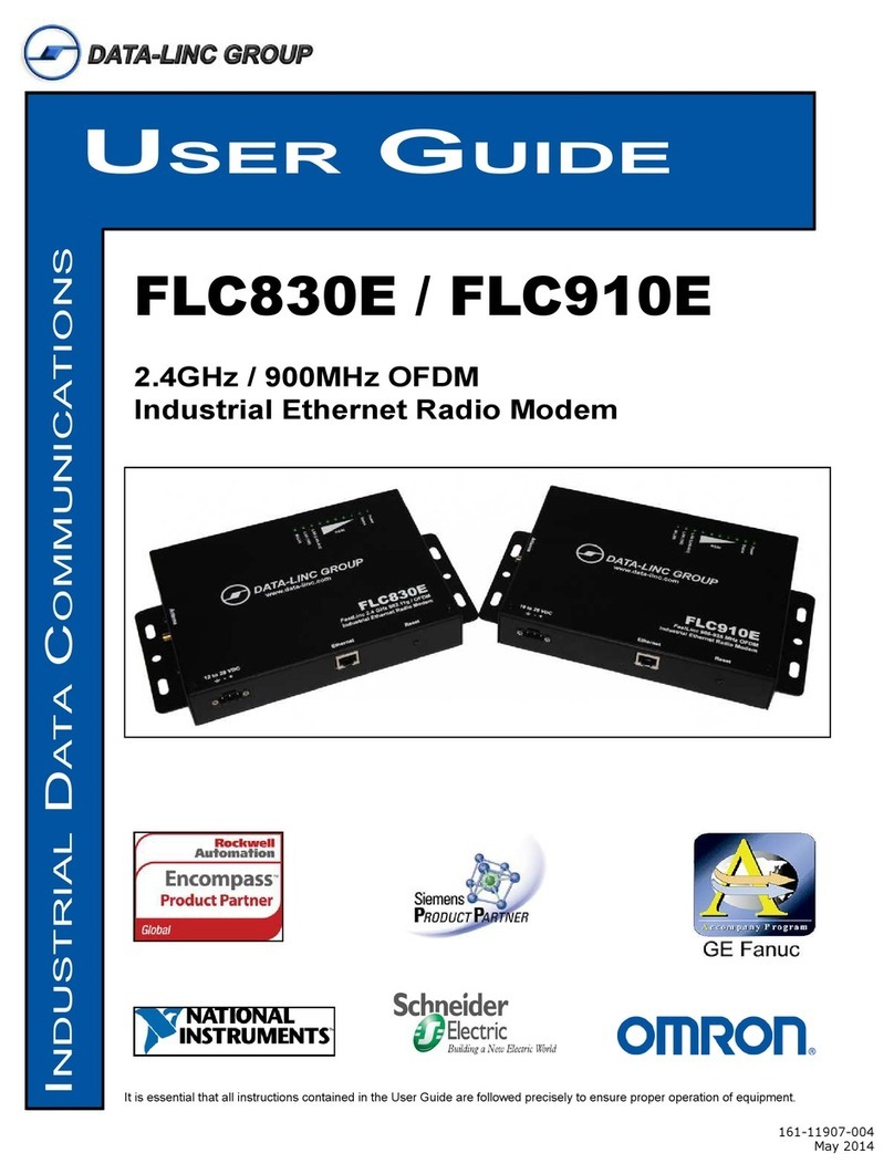
Data-Linc Group FLC910E User manual

User GUide
IndustrIal data CommunICatIons
It is essential that all instructions contained in the User Guide are followed precisely to ensure proper operation of equipment.
FLC910e
905-925 MHz OFDM
Industrial Ethernet Radio Modem

Notes:

1
FLC910E User’s Guide
PN 161-09856-001A
June 2010
Table of Contents
Warnings / FCC.................................................................................................... 2
Introduction.......................................................................................................... 3
Requirements....................................................................................................... 4
Features................................................................................................................ 4
Applications......................................................................................................... 4
Installation............................................................................................................ 5
Hardware Overview ....................................................................................................................5
Getting Started..................................................................................................... 6
Setup PC for Conguration .................................................................................................................. 6
Conguring the FLC910E ...........................................................................................................7
Setting up a system:............................................................................................................................... 8
Testing ......................................................................................................................................13
Troubleshooting ................................................................................................ 13
Technical Specications................................................................................... 14
Appendix A: Dimensions, Drawings and Accessories .................................. 15
Enclosure Dimensions..............................................................................................................15
Optional Antennas ....................................................................................................................15
Appendix B: Radio Setting Details .................................................................. 16
A – Basic Setup ........................................................................................................................17
B - Radio Settings.....................................................................................................................19
C - VBS / VLAN Settings ..........................................................................................................20
D - Access Control....................................................................................................................23
E - WDS Settings......................................................................................................................24
F - Connections ........................................................................................................................24
G - Statistics .............................................................................................................................25
H - Change Password ..............................................................................................................25
I - Remote Management...........................................................................................................25
J - Upgrade Firmware...............................................................................................................25
K - Backup/Restore Settings ....................................................................................................25
L - Event Log ............................................................................................................................25
M - Reboot................................................................................................................................25
Technical Support ............................................................................................. 26
Product Warranty .............................................................................................. 26
Return Material Authorization .......................................................................... 26
Contact Information .......................................................................................... 26

2PN 161-09856-001A
June 2010
FLC910E User’s Guide
Warnings / FCC
The FLC910E provides several wireless security options that can help make a safe and easy to setup wireless
network. Some security precautions to help make the wireless network safe are as follows:
Change the default SSID
Disable the SSID Broadcast
Change the default password
Enable MAC address ltering
Use the highest encryption type available (This may reduce the network performance).
Change the SSID and the encryption keys periodically
(See Appendix B in the VBS section for the details on changing the Security options)..

3
FLC910E User’s Guide
PN 161-09856-001A
June 2010
Introduction
Data-Linc Group (DLG) has prepared this user guide for use by customers as a guide to the proper installation, operation,
and maintenance of a FastLinc FLC910E wireless system.
The FLC910E is a member of the FastLinc Industrial Ethernet Wireless Modem Family that provides high speed, secure
wireless communications using 900MHz direct sequence and OFDM technology in a standalone form. They provide long
robust outdoor range and broader indoor coverage.
The FLC910E is an easy to congure and use wireless LAN solution. The unit can be congured using a web browser, a
SSH client connection and command-line interface (CLI) commands, or Simple Network Management Protocol (SNMP).
The FLC910E integrates into industrial plant and wireless networks with exibility and options required by networking
professionals.
The FLC910E includes Base Station (Access Point), Station Adaptor, Wireless Repeating (WDS), and Wireless
Inter-building modes for creating wireless plant networks, adding Ethernet devices to the plant network using the wireless
network, linking remote plant networks, or extending the network and coverage of the wireless network with the use of
repeating.
The FLC910E supports the use of external high gain antennas for increased performance and reliability and extending
the range of the radio signal. The unit supports the power over Ethernet standard or a wide input range 10-28 Volts DC
through the terminal connection on the front of the unit.

4PN 161-09856-001A
June 2010
FLC910E User’s Guide
Requirements
Power
10-28VDC Power connector
48V POE standard through the Ethernet pairs (turn on @ 39.5VDC)
Current Draw Max 1200mA @ 12V (during transmit)
Ethernet Operation
RJ45 - 10/100 BaseT Ethernet connected device.
RF Operation
SMA antenna or coax connection.
Ethernet Configuration
A Web browser such as Microsoft Internet Explorer 6.0 or above
-OR
A TCP Secure Shell (SSH) client
Features
-Encryption support for WEP64, WEP128, WEP152, WPA-PSK (TKIP), and WPA2-PSK (AES)
-DCHP Client support for obtaining a dynamic network IP address from a DHCP server.
-SNMP support using management information base (MIB).
-Congurable mode of operation. Select between Base Station (Access Point), Station Adaptor,
Wireless Repeating, or Inter-building modes.
-Congurable mode of modualation. Select between OFDM or CCK modulation
-Offers 900MHz reliability. The lower frequency reduces line of sight issues, minimizes multi-path fading for plant
oor and outdoor transmissions, and offers longer range communications over 2.4GHz solutions.
-Capable of transmission rates up to 54Mbps.
-Congurable transmit power. Select between full, half, quarter, eighth, and minimum.
-VLAN support for up to 8 VLANs with multiple security settings per each.
Applications
The FLC910E units are can be congured for multiple operating modes. All the modes essentially are used to extend
the Ethernet network wirelessly to reduce the cost to add Ethernet to remote sites or create an Ethernet bridge between
networks.
Base Station & Station Adaptor Modes
The FLC910E can either act as a base station or a station adaptor. As the base station the FLC910E acts as the center
point for wireless communications, allowing FLC910E congured as station adaptors to connect and build a network. As a
station adaptor the FLC910E acts as a node to attach an Ethernet device or LAN segment thru a FLC910E base station.
Wireless Repeating Mode
The FLC910E can act as a base station and repeater to repeat the transmission to other units to increase the reliability
and extend the coverage area of the wireless network. This mode uses a half duplex operation mode to communicate
with another wireless repeater and wireless stations. All the units are congured the same with the addition of the MAC
address of units to communicate with, or automatic detection of the MAC address.
Wireless Interbuilding Mode
The FLC910E can act in an interbuilding mode and create an interconnected wireless network. In this mode there is no
central point of communications any unit connected wirelessly can communicate to any other unit in the system creating a
mesh network. All the units are congured the same using the same channel and mode.

5
FLC910E User’s Guide
PN 161-09856-001A
June 2010
Installation
Unpacking the Hardware
•FLC910E OFDM Industrial High-Speed Modem
•120 VAC Wall Transformer (US Power Connector)
•Cat5 Ethernet Cable
•CD with Manual
•Quick Start Guide
•Test Antenna
The equipment was carefully packaged to prevent shipping damage. It should be free from any defect, electrical or me-
chanical, and in good operating condition. If your package contents are damaged or missing, please contact your place
of purchase immediately.
Hardware Overview
Front Panel
•Power 3 pin Pluggable Terminal Block.
Left to Right (Frame Ground, Power Ground, Power Positive)
•RJ45 Ethernet Connector.
•Reset Button.
Side Panel
•Antenna Connector with Standard Thread SMA Connector.
Top Panel
-LED Indicators:
LED Indication Note
Power Modem Power Should be on (green) at all times
Status Loading or Changing Start-Up
On = Entering Boot Mode
Off = While Finishing Boot Mode
Operating
Slow Blinking = Reset Button Held for ~ 3 Seconds
Fast Blinking = Reset Button Held for > 3 Seconds
Note: The Status LED will blink while a rmware up-
grade of reset to factory default occurs and the unit will
reboot automatically
RSSI (5 Levels) Signal Strength Shows signal strength for Station Adaptors and Wireless
Interbuilding Mode RF Links
Lan Act Lan Connection On = 100BaseT Connection
Off = 10BaseT Connection
Blinking = Lan Activity
Lan (100) 100BaseT Connection On = 100BaseT Connection
Off = 10BaseT if Lan Act is ON
W-Lan Wireless Link Status On = Wireless Connected (But no Activity)
Off = No Wireless Link
Blinking = Wireless Activity (Either Data or Linking)

6PN 161-09856-001A
June 2010
FLC910E User’s Guide
Getting Started
Connections
•Connect the Test Antenna,
•Connect the Cat5 Ethernet cable to PC (for Conguration)
•Connect the Power Supply from wall to unit
The unit will begin the boot process upon power connected.
Note: The boot process takes about 70 seconds before the unit will be fully operational and congurable.
The LAN Link LED should be lit for a connection to the PC.
Setup PC for Configuration
Congure the PC TCP/IP settings to match the network for the FLC910E to be congured. (Set the PC to a static
IP Address of 192.168.1.X, where X can be from 2 to 254, and set a Subnet Mask of 255.255.255.0)
Note: You will need privileges on your PC to be able to access the IP Address 192.168.1.1. This might be
changing your current IP address to be in the same subnet (ex. 192.168.1.2 with subnet mask 255.255.255.0), if
you are not already on that subnet. (See Appendix B for more information on changing your IP Address)
Default FLC910E Settings
IP Address 192.168.1.1
User Name admin
Password password
Mode Base Station
ESSID Wireless
Security None Set
Wireless Device
Name
DEVICExxxxxx
(xxxxxx = Last 6 digits of MAC Address)
Channel /
Frequency
CH 3 / 918 MHz
Bandwidth 5 MHz
Example PC Settings for Conguration:

7
FLC910E User’s Guide
PN 161-09856-001A
June 2010
Configuring the FLC910E
•Start a web browser client such as Internet Explorer© (6.0 or greater) or Mozilla Firefox©.
•In the address bar type: “http://192.168.1.1” to access the web based conguration.
Accept the “Security Alert” or “I Understand the Risks” and “Conrm Security Exception”.
Note: Firefox users must also click to Conrm Security Exception.
Note: To return the FLC910E to the default conguration and password, after the unit has fully booted, press and
hold the reset button for 5 seconds until the Status LED begins to ash quickly. This will reboot and reset the unit
to default conguration.
•Login into the unit using the defaults:
User Name: (admin)
Password: (password)
After successfully logging in the About page is
displayed and on the left margin of the browser is
the menu with information and setup options.
(See Appendix B for full details about the left
margin menu items and settings)

8PN 161-09856-001A
June 2010
FLC910E User’s Guide
Setting up a system
Basic Setup:
In the basic setup menu you have the option to set a differ-
ent wireless device name then the default, which is
DEVICExxxxxx, where the xx is a hexadecimal number
related to last 6 digits of the MAC address.
For a system the IP Addresses on the units must be unique
and use the same IP Subnet Mask. After changing the IP
Address, the PC IP address may have to change to be on
the same network to continue conguration.
Operating modes (Radio Settings):
The FLC910E can operate as a base station, station adaptor,
wireless repeater, or in wireless interbuilding mode to create
a wireless network. The following with describe the setup of
each type of unit and the connectivity between the units.
Base Station:
The “Base Station” operates as the central unit for the
connectivity. “Station Adaptors” and “Wireless Repeaters”
will connect and communicate with a “Base Station”.
To setup the “Base Station” select “Base Station” from the
drop down menu of “Operating Mode”.
Apply this setting; the unit will be in base station mode.
Select the type of modulation OFDM or CCK.
Select the data rate to use. Note: Best will try to establish
the highest possible data rate, but for longer distances using
a xed lower rate may improve system reliability.
Select the output power, from full – min depending on
distance.
Select the bandwidth to use. The bandwidth selected will
determine the usable channels / frequency.
Select the Channel to use based on the table below:
Bandwidth / Channels Available
20 MHz CH2 or CH3
10 MHz CH1, CH2, CH3, or CH4
5 MHz CH1, CH2, CH3, or CH4
Apply the setting changes, if any.

9
FLC910E User’s Guide
PN 161-09856-001A
June 2010
Select the Edit button next to Base Station ID or VBS/VLAN Settings from the left. This will go to the VBS / VLAN Settings
page.
Select the Prole and click the edit button.
Choose the SSID and Network Authentication settings for the network.

10 PN 161-09856-001A
June 2010
FLC910E User’s Guide
Authentication Types / Options
Open System None, WEP64, WEP128, and WEP152
Shared Key WEP64, WEP128, and WEP152
WPA-PSK TKIP
WPA2-PSK AES
If using encryption, remember the authentication type and key for use when setting up the station adaptors that
communicate with this base station.
Apply the settings.
The conguration is complete for the “Base Station”; some recommended additional actions are as follows:
•Change the unit password.
•Make a backup of the settings and save the le.
Station Adaptor:
The “Station Adaptor” can connect to a “Base Station” or “Wireless Repeater”.
To setup the “Station Adaptor” select “Station Adaptor” from the drop down menu of “Operating Mode”.
Apply this setting; the unit will be in “Station Adaptor” mode. If the base station is set to broadcast the SSID, select the
site survey button to join the SSID. If SSID is disabled enter the SSID and the use BSSID MAC from the Base station.
The data rate and bandwidth need to match the base station for a connection to be established.
Apply the settings.
Select the VBS/VLAN from the left margin to setup the security settings.
Select the sta_prole and click the edit button.

11
FLC910E User’s Guide
PN 161-09856-001A
June 2010
Select the Network Authentication and Data Encryption that is the same as the base station to associate with.
Authentication Types / Options
Open System None, WEP64, WEP128, and WEP152
Shared Key WEP64, WEP128, and WEP152
WPA-PSK TKIP
WPA2-PSK AES
Apply the settings.
The “Station Adaptor” should be connected to the “Base Station” and the RSSI LEDs on the top should indicate the signal
strength.
Wireless Repeater:
The FLC910E can operate as a “Wireless Repeater” to repeat “Base Station” or other “Wireless Repeaters” to extend the
area of the wireless network coverage. “Station Adaptors” can connect to the “Wireless Repeater”.
This unit will be setup similar to the “Base Station” since this device operates as a “Base Station” with repeating or WDS
operation. The security prole for BS_prole1 (or as many that are Enabled) and the wds_prole are active.
To setup the “Wireless Repeater” select “Wireless Repeater” from the drop down menu of “Operating Mode”.
Apply this setting; the unit will be in “Wireless Repeater” mode.
Select the type of modulation OFDM or CCK.
Select the data rate to use.
Note: Best will try to establish the highest possible data rate, but for longer distances using a xed lower rate may
improve system reliability.
Select the output power, from full – min depending on distance.
Select the bandwidth to use. The bandwidth selected will determine the usable channels / frequency.
Select the Channel to use based on the table below:
Bandwidth / Channels Available
20 MHz CH2 or CH3
10 MHz CH1, CH2, CH3, or CH4
5 MHz CH1, CH2, CH3, or CH4
Apply the setting changes, if any.
Select the Edit next to Base Station ID, this will go to the VBS / VLAN Settings menu page.
Select the Prole and click the edit button.
Choose the SSID and Network Authentication settings for the network. For the network to repeat use the wds_prole for
the encryption settings.

12 PN 161-09856-001A
June 2010
FLC910E User’s Guide
Apply the settings.
Using the WDS Settings enter the “Base Station” or other “Wireless Repeater” MAC Address of the unit to repeat, if the
unit to connect with is using encryption, enter the type and key in the wds_prole in the VBS/VLAN Settings.
Note: using automatic mode for WDS Settings will disable the “Base Station” operation and only function as a repeater.
Base Station Prole:
Authentication Types / Options
Open System None, WEP64, WEP128, and WEP152
Shared Key WEP64, WEP128, and WEP152
WDS Prole:
Authentication Types / Options
Open System None, WEP64, WEP128, and WEP152
Apply the settings.
The “Wireless Repeater” is congured. It will connect to the “Base Station” to repeat and the RSSI LEDs on the top
should indicate the signal strength.
InterBuilding Mode:
The FLC910E is capable of a proprietary version of wireless repeating mode. This mode is non- standard so it increases
the security of the communications. For this mode Channel / Frequency, Modulation, Bandwidth, and Encryption type and
key must match for the system. Access control can also be used in this mode for limiting the devices that can connect to
the wireless network.
To setup the “Wireless Interbuilding” select “Wireless Interbuilding” from the drop down menu of “Operating Mode”.
Apply this setting; the unit will be in “Wireless Interbuilding” mode.
Select the type of modulation OFDM or CCK.
Select the data rate to use. Note: Best will try to establish the highest possible data rate, but for longer distances using a
xed lower rate may improve system reliability.
Select the output power, from full – min depending on distance.
Select the bandwidth to use. The bandwidth selected will determine the usable channels / frequency.
Select the Channel to use based on the table below:
Bandwidth / Channels Available
20 MHz CH2 or CH3
10 MHz CH1, CH2, CH3, or CH4
5 MHz CH1, CH2, CH3, or CH4

13
FLC910E User’s Guide
PN 161-09856-001A
June 2010
Apply the setting changes, if any.
Select the VBS / VLAN Settings menu option from the left margin.
Select the inter_prole and click the edit button.
Select the encryption type and key.
Authentication Types / Options
Open System None, WEP64, WEP128, and WEP152
Apply the settings.
Testing
To verify connectivity a simple ping command can be used. Ping a device on the LAN connected to the opposing
FLC910E or the FLC910E modem itself. For more detailed information or troubleshooting information please refer to the
user’s guide.
Troubleshooting
Some helpful things to know before trouble shooting a FLC910E wireless network:
•The type of connection (Base Station/Station Adaptor/Wireless Repeater or Wireless Interbuilding).
•The network name (SSID) and/or BSSID.
•The type of network authentication and encryption used.
•The IP Address of the unit, if it is static.
•Does the unit respond to a ping request?
•The subnet mask of the unit.
I can’t connect to the “Base Station” or “Wireless Repeater”.
Verify the Network Authentication Type and Pass phrase or Key matches.
In a “Wireless Repeater” make sure the WDS setting “Use Automatic” is not used for “Station Adaptor” connectivity.
If using Access Control make sure the MAC address of the device is allowed to connect to the “Base Station” or “Wireless
Repeater”.

14 PN 161-09856-001A
June 2010
FLC910E User’s Guide
Technical Specications
Input Voltage Range: 10-28VDC
Max Current Draw: 1200mA @ 12VDC
Power Connector: 3 Position Pluggable Terminal Block
Ethernet Connector: RJ45
RF Specication:
•Operation Modes: Base Station, Station Adaptor, Wireless Repeater, and Wireless Interbuilding
•RF Frequency Range: 905-925 MHz
•RF Modulation based on connection speed (Mbps): (48&54 QAM-64), (24&36QAM-16), (12&18 QPSK), and (6&9
BPSK) using OFDM or DSSS(CCK).
•RF Data Rates: 54, 48, 36, 24, 12, 9, and 6 Mbps
•RF Channel Bandwidth: 5MHz, 10MHz, and 20MHz
•RF Receiver sensitivity less than 10% packet error rate: 54 Mbps: ≤ -72 dBm ± 2 dBm , 6 Mbps: ≤ -92 dBm ± 2 dBm
•RF Transmit Power: 25dBm ± 1.5dBm
•RF Antenna Impedance: 50 ohms
•RF Antenna Connector: Standard Thread Female SMA
Operation Temperature: -20C-75C (90% relative humidity (non-condensing))
Enclosure Material: 18 Gauge Steel
Enclosure Dimensions (without connectors: 7.6Wx5.6Lx1.4H inches (19.3Wx14.3Lx3.6H cm) without mounting feet or
9.4Wx5.6Lx1.5H inches (24Wx14.3Lx3.7H cm) using the mounting feet.
Weight: 2.3 lbs (1.05 kg)

15
FLC910E User’s Guide
PN 161-09856-001A
June 2010
Appendix A: Dimensions, Drawings and Accessories
Enclosure Dimensions
Optional Antennas
A-O6/ADJ 900MHz Omnidirectional Antenna 6”L, 0db Gain, SMA Female Connector
A-OB 900MHz Omnidirectional Antenna, 12”L, 5.14dBi (3dBd) Gain, Mounting Brkt.
A-O7B 900MHz Omnidirectional Antenna, 22”L, 7.14dBi (5dBd) Gain, Mounting Brkt.
A-Y8B 900MHz Yagi Directional Antenna, 17.5”L, 8dBi Gain, 4 Element, Mounting Brkt.
A-Y11B 900MHz Yagi Directional Antenna, 29.3”L, 11dBi Gain, 7 Element, Mounting Brkt.
1.5 in

16 PN 161-09856-001A
June 2010
FLC910E User’s Guide
Appendix B: Radio Setting Details
After successfully logging in the About page is the displayed page. This gives you the
current device name, MAC Address, and the rmware version.
Located on the left margin of the page is the list of setting to change for conguration.
A brief list of the elds in each section is as follows:
Basic Setup: (Described in detail in Part A)
Device Name, Ethernet Data Rate, Spanning Tree Protocol, VLAN(802.1Q),
Management VLAN ID, IP Address options, and Time server options.
Radio: (Radio Settings) (Described in detail in Part B)
Operating Mode, Modulation, Channel/ Frequency, Data Rate, Output Power,
Bandwidth, VQoS / TDM, Regatta Mode, and Advanced Parameters.
VBS/VLAN Settings: (Described in detail in Part C)
The Security Proles for Base Station, Station Adapter , WDS and Wireless
Interbuilding mode and VLAN (802.1Q) Setup.
Access Control: (Described in detail in Part D)
To add and remove access control based on MAC Addresses.
WDS Control: (Peer-to-Peer Links) (Described in detail in Part E)
Setup wireless point to point or multipoint WDS systems based on MAC
Addresses or automatic repeating.
Connections: (Described in detail in Part F)
Shows the units connected to the device or connection status of the
Station adaptor.
Statistics: (Described in detail in Part G)
Shows the Ethernet and Wireless statistics for a selected connection group.
Change Password: (Described in detail in Part H)
Changes the password with the known current password.
Remote Management: (Described in detail in Part I)
Remote Console (SSH) and SNMP options.
Upgrade Firmware: (Described in detail in Part J)
Load a new rmware le.
Backup/Restore Settings: (Described in detail in Part K)
Save or load store congurations.
Event Log: (Described in detail in Part L)
SysLog setup and Event Log.
Reboot: (Described in detail in Part M)
Reboots the FLC910E.

17
FLC910E User’s Guide
PN 161-09856-001A
June 2010
A – Basic Setup
Wireless Device Name: This is the name given to the unit for identication purposes; it is only viewable when logged into
the unit. It can only contain up to fteen (15) numbers 0-9, letters A-Z and/or a-z, or hyphens.
Ethernet Data Rate: Automatic – will automatically detect 10BaseT or 100BaseT Ethernet connection
•T-Base10Mb – force to 10BaseT Ethernet connection
•T-Base100Mb – force to 100BaseT Ethernet connection
Spanning Tree Protocol(STP): Enable or disable the use of the spanning tree protocol. Enabling STP can prevent data
storms or loops in the network.
VLAN(802.1Q): Enable or disable the use of VLAN separation. Enabling VLAN allows multiple bridged networks to
transparently share the same physical network link without sharing of information between the networks.
Management VLAN ID: The ID of the VLAN this device will operate on.

18 PN 161-09856-001A
June 2010
FLC910E User’s Guide
IP Address: Manual of DHCP assigned. If DHCP assigned the unit will acquire a network address from a DHCP server.
Using Manual settings:
•IP Address: Network address for the device.
•Subnet Mask: Mask for determining the number of nodes on that network.
•Gateway: Address for a gateway for routing data to another network.
•Primary DNS: Dynamic Name Server for resolving names to IP Address.
•Secondary DNS: same as above
Time Server: Allows the time to be synchronized by using a NTP time server.
•Time server: Address of the time server
•Time Server Port: The port that the server is running on to synchronize time.
•Time Zone: Time zone for the location of the unit.
•Current Time: shows the current time.
Other manuals for FLC910E
1
Table of contents
Other Data-Linc Group Radio Modem manuals
