Datum Trak-Slider User manual

Trak-Slider Instructions
American Filing Solutions P.O. Box 891719, Temecula, CA 92589 Toll Free: (888) 891-1970 x 8958 Fax: (888) 891-9970 Email: [email protected] www.FilingToday.com

1/4-20 x 3/4"
Hex Head Bolt
1/4-20 x 1/2"
Allen Cap Screw
1/4-20 x 3/8"
Pan Head Phillips
Machine Screw
#8 x 3/8"
Tek Screw Phillips
1/4-20 Flanged
Hex Nut
1/4-20 Nylock Nut
1/4 USS Flat Washer
1/4-20 "J" Type
Tinnerman Nut Wheel End Stop
3/4"SQ x 1/2" High
Black Self Adhesive
Rubber Bumper
3/4" Hex x 5/16-18 x 1 1/4" Max
Hex Stem/Base Glide
3/16" Allen Key
Short Arm
NOTE: All Hardware shown actual size.
Gusset
Rivet
2
American Filing Solutions P.O. Box 891719, Temecula, CA 92589 Toll Free: (888) 891-1970 x 8958 Fax: (888) 891-9970 Email: [email protected] www.FilingToday.com

Top Stabilizer Channel
A11858-36
Connector Channel
B11810-36
End Cap
B11798
Stainless Steel Front Cap
B11811-36
Conversion Plate
B11808
Tri-Slider Top Stabilizer
Bracket Assembly
TSRB
Tri-Slider Hat Channel
TSHC
Carriage Assembly
D11885
Decking
D11812
Rail Assembly
D11884
PARTS LIST
Safety Stop
A11891
One Piece Bi-Slide Roller Bracket
B12764
3
American Filing Solutions P.O. Box 891719, Temecula, CA 92589 Toll Free: (888) 891-1970 x 8958 Fax: (888) 891-9970 Email: [email protected] www.FilingToday.com

NOTE: All shelving used on a Datum Bi/Tri Slider system must have the same overall height. The
shelving must also have a minimum of 1-1/2" of clearance from the floor to the filing surface of the
bottom shelf.
TOOLS REQUIRED: 7/16" wrench & socket set
7/32" socket
small flat blade screwdriver
phillips screwdriver
5/16" drill bit
screw gun
4 foot bubble level
water level, laser level or transit
hammer
STEP 1: Assemble the rear stationary shelving sections according to the manufacturer's instructions
and position on the floor. Be sure to level this row before moving on to the next assembly step.
When using Datum stackable shelving you must use 2" bases with built-in leveling guides and 1"
tops. It is recommended that stationary sections be secured to wall.
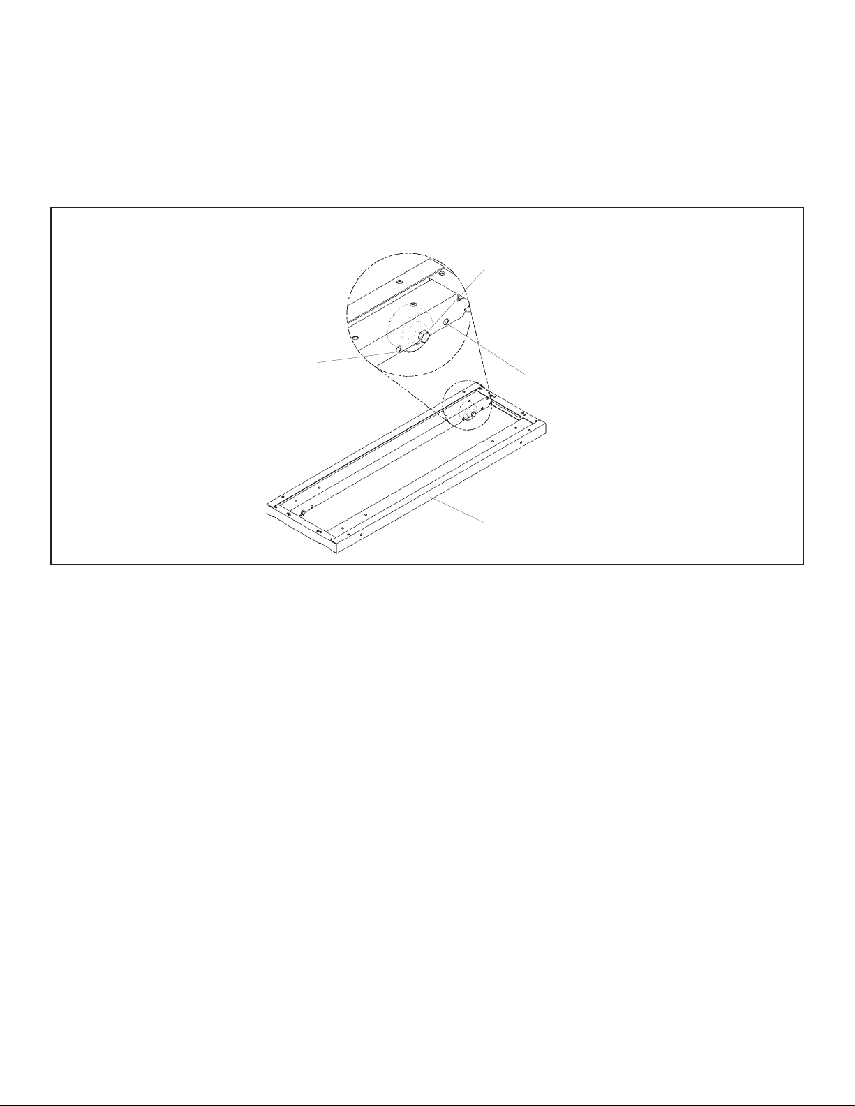
STEP 2: Attach the top stabilizer channels to the tops of the stationary sections. Position each
channel flush with the front and even with the sides of each of the top section (Holes are pre-
punched in the 1" high top when using Datum Stackable Shelving.) Attach the channel using three
1/4-20 X 3/4" bolts and flange nuts. Repeat for each rear stationary section. (See figure 1.)
STEP 2A: FOR TRI/QUAD SLIDER SYSTEM ONLY. Follow directions in step 2; however, attach
additional top stabilizer channels directly in back of the first row using three 1/4-20 x 3/4" bolts and
flange nuts. (As described in step 2, holes are pre-punched for Bi and Tri-Slider hat channels only
when using Datum 1" high tops.) Repeat for each rear stationary section.
NOTE: For Quad-Slider systems it will be necessary to pre-drill tops for attachment of top stabilizer
channel.
4
American Filing Solutions P.O. Box 891719, Temecula, CA 92589 Toll Free: (888) 891-1970 x 8958 Fax: (888) 891-9970 Email: [email protected] www.FilingToday.com

1/4-20 x 3/4" Hex Head Bolt
1/4-20 Flanged Hex Nut
Top Stabilization Channel
FIGURE 1
5
American Filing Solutions P.O. Box 891719, Temecula, CA 92589 Toll Free: (888) 891-1970 x 8958 Fax: (888) 891-9970 Email: [email protected] www.FilingToday.com
NOTE: All systems will consist of one starter rail assembly and the required amount of add-on rail
assemblies. Example: A B632LT consists of (1) #36LTBSST; starter and (2) 36LTBSAO; add-on
(Part numbers are found on each box.) The starter rail assembly contains one section of rail and
hardware. The add-on rail assembly contains one section of rail, hardware and one mobile carriage.
All mobile carriages are preset at the factory to include 2" of overtravel. Systems up to a 4/3
configuration for Bi/Tri/Quad do not require overtravel. Overtravel can be increased or decreased as
needed, please refer to the diagram below for more information.
STEP 3: Install 12 leveling glides per rail section making sure that each one is screwed in and flush
with the bottom of the rail assembly.
STEP 4: Position stationary connector channels on the front bottom of each stationary base. Attach
each connector channel using a minimum of (4) #8 x 3/8" tek screws (See figure 2, detail A).
STEP 5: Join rail assemblies together using (4) 1/4-20 X 3/4" bolts and flange nuts. Rail sections will
have corresponding holes for attaching side to side (See figure 2, detail B2). Position rail assembly
on floor, do not attach to connector channel at this time.
STEP 6: Attach the deck end cap to the rail section starting from the left end of the rail assembly
using (2) 1/4"-20 X 3/4" bolts and flange nuts (See figure 2; details B1, B3). Repeat procedure for
right side of system.
STEP 6A: FOR TRI/QUAD SLIDER SYSTEMS ONLY. Position additional row(s) of rail sections in
front of Bi-Slider rail sections described above. Attach deck end cap to Bi-Slider and Tri-Slider track
assembly using (4) 1/4-20 X 3/4" bolts and flange nuts. Repeat procedure for right side of system.
STEP 7: Attach the assembled rail section to the connector channel. The rail assembly will have
corresponding slots which will secure to the connector channel. (See figure 2).
Standard Placement Of Wheel Assembly
For 2" Overtravel (Center Holes). No Need
To Adjust For Systems Up To A 7/6
Bi/Tri/Quad Configuration.
Placement Of Wheel Assembly For No
Overtravel (Outside Holes). Adjustable If
Necessary Up To A 4/3 Bi/Tri/Quad
Configuration.
Placement Of Wheel Assembly For 4"
Overtravel (Inside Holes). For Systems
Greater Than 7/6 Configurations.
Typical Bi/Tri Slider Mobile Carriage
Proper Placement Of Carriage Wheels For Overtravel
6
American Filing Solutions P.O. Box 891719, Temecula, CA 92589 Toll Free: (888) 891-1970 x 8958 Fax: (888) 891-9970 Email: [email protected] www.FilingToday.com

FIGURE 2
DETAIL A
DETAIL B
DETAIL C
DETAIL D
Tek Screw
Connector Channel Glide
1/4-20 Flanged
Hex Nut
End Cap
Front Cap
Support
7
American Filing Solutions P.O. Box 891719, Temecula, CA 92589 Toll Free: (888) 891-1970 x 8958 Fax: (888) 891-9970 Email: [email protected] www.FilingToday.com

STEP 8: LEVELING: Determine highest point on the rail assembly. Working out from this point,
level the rail by adjusting the leveling glides. IMPORTANT! For system to function properly all rails
must be level from left-to-right, front-to-back, and rail to rail. All leveling glides must be in contact
with the
floor.
STEP 9: Install decking. Deck sections interlock with the rail assembly and should be flush with the
top of the rails when installed. (See figure 3).
STEP 9A: TRI/QUAD SLIDER SYSTEMS ONLY. Install additional sections of decking which span
between two rail assemblies (See figure 3).
STEP 10: Attach stainless steel front cap to each rail section by snapping over front rail cross-mem-
bers (See figure 3, Detail C). Repeat for remaining rail sections.
FIGURE 3
DETAIL C
DETAIL D
Stainless Steel Front Cap
1/4-20
Allen Cap Screw
Wheel End Stop
Decking
STEP 11: Attach 2" bases to mobile carriage using (4) 1/4-20 x 3/4" hex bolt and 1/4-20 nylock nut
(See figure 4). NOTE: When using Datum 2" bases, the carriages and bases will have pre-punched
holes for attachment.
STEP 11A: When installing 4-post shelving conversion plates are required to prevent shelves from
shifting on carriage (See figure 4). Assemble four-post shelving as per manufacturer's instructions
and attach to carriage. NOTE: It is recommended that single rivet shelf supports (Not included) be
used for secure attachment to mobile carriage.
STEP 12: Assemble Datum ThinStak Shelving, as per assembly instructions supplied, and attach to
2" base.
8
American Filing Solutions P.O. Box 891719, Temecula, CA 92589 Toll Free: (888) 891-1970 x 8958 Fax: (888) 891-9970 Email: [email protected] www.FilingToday.com

STEP 12B: Note: Gussets are used on moveable shelving units only. Assemble shelving as per
shelving instructions. Before securing top cover to top tier, slide a gusset into each rear corner of the
top cover and secure with 1/4-20 screws and nuts as shown. Secure remaining screws and nuts as
shown in shelving instructions. Repeat steps for all moveable units.
STEP 13: Install rolling carriages onto rail.
FIGURE 4
1/4-20 x 3/4" Hex Head Bolt
1/4-20 x 3/4" Hex Head Bolt
2" Stackable Base
Carriage Assembly
Conversion Plate
1/4-20 Nylock Nut
1/4-20 Nylock Nut
Self Adhesive Bumper
Install Rivets Here
4 Holes Per Tier
Install Additional Rivets Here When
Using On Trak-Slider Carriage
1/4-20 Pan Head Phillips
Screw
1/4-20 Flange Nut
Gusset
Tier
Top Cover
Important: Step 12a-12b for Datum Thinkstak Shelving
STEP 12A: Each movable shelf section will require 6 rivets per shelf opening. Please refer to the diagram
below for proper rivet placement. Additional rivets are included in each hardware kit.
9
American Filing Solutions P.O. Box 891719, Temecula, CA 92589 Toll Free: (888) 891-1970 x 8958 Fax: (888) 891-9970 Email: [email protected] www.FilingToday.com

FIGURE 5
1/4-20 x 3/4" Hex
Head Bolt (3 reqd.)
1/4-20 Nyloc Nut
(3 reqd.)
1/4-20
Nylock Nut
(Typical)
Quad-Slider
Top Stabilizer
1/4-20 x 3/4"
Hex Head Bolt
(Typical)
Tri-Slider
Top
Stabilizer
Tri-Slider
Hat
Channel
Quad-Slider
Hat
Channel
Top Cover
(Movable Unit
New Style Roller
Bracket
1/4" Flat Washer
STEP 14: Mount a top stabilizer bracket assembly to the top of each Bi-Slider rolling section using (3) 1/4-20 x 3/4" hex
bolts, (3) flat washers and (3) 1/4-20 nylock nuts (holes are prepunched when using 1" tops). See figure 5.
STEP 14A: Tri/Quad Slider system only. Mount the Tri-Slider hat section to each front rolling section using eight hex
1/4-20 x 3/4" bolts and (8) 1/4-20 nylock nuts. Attach Tri-Slider top stabilizer bracket to hat channel using (4) hex 1/4-20
bolts (See figure 5).
NOTE: If the top roller mount assembly rubs along the stabilizer channel, the roller must be adjusted. Loosen the two
bolts which secure the rollers to the roller bracket assemblies. Adjust so that each roller moves freely in the channel.
Firmly re-tighten each bolt after adjustment.
STEP 15: After all carriages have been installed, install wheel end stops onto rail using one 1/4"-20 x 1/2" allen cap
screw (See figure 3-detail D). One pair of end stops are required for each end of system.
STEP 16: Remove (1) 1/4-20 x 3/4" hex head bolt from far left and far right side of top stabilizer channel. Insert over-
head safety stop to each end of top stabilizer channel and re-attach using the 1/4-20 x 3/4" nut and bolt
(See figure 6).
STEP 17: Install 1 pair of black self-adhesive rubber bumpers to each rolling carriage (See figure 4). NOTE: One pair
is needed between two mobile carriages.
10
American Filing Solutions P.O. Box 891719, Temecula, CA 92589 Toll Free: (888) 891-1970 x 8958 Fax: (888) 891-9970 Email: [email protected] www.FilingToday.com

FIGURE 6
Safety Stop
SAFETY PRECAUTIONS
1) Read through these instructions again insuring that all steps were completed.
2) Recheck and tighten any loose bolts or fittings.
3) Check to see that all top stabilizer channels are securely fastened to the tops of the stationary sections.
4) Check to insure that the end stops are securely fastened to the rail assemblies.
5) If attaching stationary section to wall make sure to follow manufacturers recommendations.
LOADING FILES
Loading a Bi/Tri Slider system in the correct manner is very important. It balances the paper weight load
throughout the entire system and minimizes the odds of having to move the rolling sections every time the system is
accessed. Careful planning of this phase of the installation will make filing and retrieval a lot easier.
It is recommended the system be loaded first from the left rear section followed by the first rolling section on the
left side of the Bi-Slider. If a Tri-Slider is installed, next load the first rolling section on the left side of the front row
(See figure 7).
Repeat loading from the rear to the front until completed.
RE-LEVELING THE DATUM BI/TRI SLIDER SYSTEM
It rarely occurs; however, after the Bi/Tri Slider system has been loaded, the rolling sections may begin to move
or creep on their own. While this problem is more annoying than hazardous, it may be corrected by re-leveling the rail
assembly. The Datum Bi/Tri Slider system has been designed so that the deck plates can be easily removed for access
to the leveling glides.
To remove the deck plates, move the rolling sections to one side. Then, insert a slotted screw driver into the slot
provided on the decking and with even pressure pull the deck plates up and remove.
Next, re-adjust the leveling glides by turning them one-quarter turn at at time either raising or lowering the rail
assembly to the desired height to stop the unwanted movement. It is very important that all leveling glides maintain con-
tact with the floor. When this adjustment has been completed, re-install the deck plates.
If other problems occur which have not been addressed in these assembly instructions, please call Customer
Service at 888-891-1970 x 8958.
Thank you for purchasing and installing this system.
1
2
3
4
5
6
7
8
9
1
2
4
5
7
8
10
11
13
36912
BI-SLIDER
TRI-SLIDER
FIGURE 7
BI-SLIDER
TRI-SLIDER
11
American Filing Solutions P.O. Box 891719, Temecula, CA 92589 Toll Free: (888) 891-1970 x 8958 Fax: (888) 891-9970 Email: [email protected] www.FilingToday.com
Table of contents
Popular Indoor Furnishing manuals by other brands

WATSON
WATSON 360.394.1300 Assembly

Sjobergs
Sjobergs 701232 Assembly instructions

Studio Designs
Studio Designs HOME CORBEL 74000 Assembly instructions

PHI VILLA
PHI VILLA THD5-0601-118 Use and care guide

Livarno Living
Livarno Living 114815 Assembly instruction

Cooper Lighting
Cooper Lighting Cambria 403 Specification sheet


FMD Furniture
FMD Furniture HALLO 2 210-002 Assembly instructions

Alvin
Alvin Comfort Economy CH277 Assembly instructions

Easylife
Easylife EL6697 instruction manual

Triarch
Triarch Indoor Lighting 33190/1 instructions

Mocka
Mocka Jesse Entertainment Unit Assembly instructions

Assa Abloy
Assa Abloy Traka Touch Series user guide