DAVIS DriveRight 8127 User manual

Includes:
GPS/Wireless Interface Module (#8127)
GPS Module (#8128)
Wireless On-Board Module (#8129)
GPS/Wireless System
Installation Manual

For Products: #8127, #8128, #8129 Rev. C (8/22/06)
Davis Instruments Part Number: 7395.221 GPS/Wireless System Installation Manual
© Davis Instruments Corp. 2006. All rights reserved.
DriveRight®is a registered trademark of Davis Instruments Corp. Velcro®is a trademark of Velcro
Industries, Manchester, NH.
3465 Diablo Avenue, Hayward, CA 94545-2778 U.S.A.
510-732-9229 • Fax: 510-732-9188
Regulatory Compliance
E Mark
This product complies with the essential protection requirements of the EC EMC Vehicle Directive 95/54/EC.
CE EC EMC Compliance
This product complies with the essential protection requirements of the EC EMC Directive 89/336/EC.
FCC Part 15.247
FCC ID: OUR-XBEEPRO
IC RSS-210
IC ID: 4214A-XBEEPRO
FCC Part 15 Class B Registration Warning
This equipment has been tested and found to comply with the limits for a Class B digital device, pursuant to Part 15 of the
FCC Rules. These limits are designed to provide reasonable protection against harmful interference in a residential installa-
tion. This equipment generates, uses, and can radiate radio frequency energy and, if not installed and used in accordance
with the instructions, may cause harmful interference to radio communications.
However, there is no guarantee that interference will not occur in a particular installation. If this equipment does cause harm-
ful interference to radio or television reception, which can be determined by turning the equipment on and off, the user is
encouraged to try to correct the interference by one or more of the following measures:
• Reorient or relocate the receiving antenna.
• Increase the separation between the equipment and receiver.
• Connect the equipment into an outlet on a circuit different from that to which the receiver is connected.
• Consult the dealer or an experienced radio/TV technician for help.
Changes or modification not expressly approved in writing by Davis Instruments may void the warranty and void the user's
authority to operate this equipment.

1
GPS/Wireless System
Installation Manual
This manual provides the instructions necessary to install the DriveRight GPS/
Wireless Interface Module (#8127), GPS Module (#8128), and the Wireless
On-Board Module (#8129) with your DriveRight 600 or 600Edevice.
Refer to the DriveRight 600 User’s Guide or the DriveRight 600EUser’s
Guide, and the DriveRight Fleet Management Software Online Help for
instructions on how to configure and use the components in the GPS/Wireless
System.
Note: The GPS Module must be enabled in the DriveRight device prior to installation via the
DriveRight Fleet Management Software (FMS) for the module to function.
The Wireless On-Board Module itself must be configured in the Fleet Management
Software for your fleet before installation in a vehicle. See the FMS Online Help System
for information configuring both of these modules.
Some components of the GPS/Wireless System may have compatibility issues
with certain DriveRight devices. The compatibility limitations in the product
families are indicated in the chart below:
*Requires one #8127 GPS/Wireless Interface Module per vehicle installation.
Note: The GPS Module (#8128) is only compatible with the DriveRight 600Edevice (#8126). It
cannot be used with older DriveRight devices. The GPS/Wireless Interface Module
(#8127) and Wireless On-Board Module (#8129) are compatible with both DriveRight 600
and 600Edevices but not with earlier DriveRight models.
Device GPS Device Wireless Device
DriveRight 600 #8156 GPS Module #8157 Wireless On-Board
Module #8129*
DriveRight 600E
#8126 GPS Module #8128* Wireless On-Board
Module #8129*
2
Components and Mounting Hardware
Components and Mounting Hardware
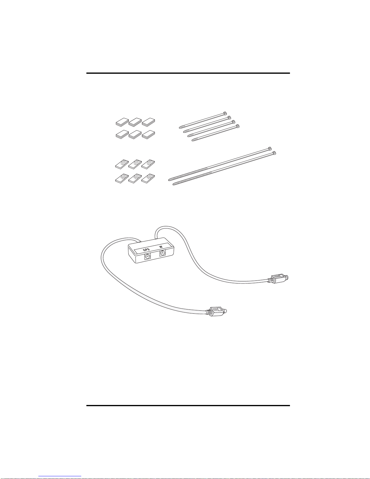
The following mounting hardware kit is included with GPS/Wireless Interface
Module (#8127) and can be used with all three components:
The GPS/Wireless Interface Module (#8127) should come with the mounting
hardware (above) and the component shown below:
Velcro Tape (6 pair)
®
Double-Sided
Foam Tape (6 strips)
5.5'' Cable Ties (4)
12'' Cable Ties (2)
GPS\Wireless
Interface Module
(#8127)

3
Components and Mounting Hardware
The GPS Module (#8128) is sold separately and comes with the component
shown below:
The Wireless On-Board Module (#8129) is also sold separately and comes
with the component shown below:
GPS Module
(#8128)
Wireless On-Board Module
(#8129)
4
GPS/Wireless System Wiring Diagram
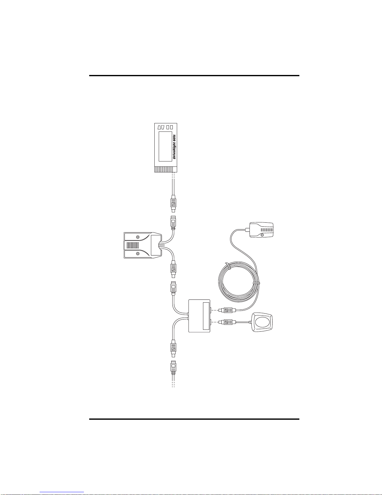
GPS/Wireless System Wiring Diagram
The following wiring diagrams display all the possible wiring solutions for
connecting the GPS/Wireless Interface Module, GPS Module, and Wireless
On-Board Module to an existing DriveRight 600 or 600Esystem.
Wiring the GPS/Wireless System with a DriveRight600E
WGPS
SmartCard
On-Board
Reader
#8104 or #8105
(optional)
DriveRight 600E
#8126
Wireless
On-Board
Module
#8129
8′ Cable
(244 cm)
GPS
Module
#8128
GPS/Wireless
Interface Module
#8127
Digital
Adapter Cable

5
GPS/Wireless System Wiring Diagram
Wiring the GPS/Wireless System with a DriveRight 600
WGPS
SmartCard
On-Board
Reader
#8104 or #8105
(optional)
DriveRight 600
#8156
Wireless
On-Board
Module
#8129
GPS/Wireless
Interface Module
#8127
Digital
A
dapter Cable
07381.129
(sold separately)
Required if #8157
is installed
GPS Module
#8157
(optional)
Requires
07381.129
to be installed
GPS
Antenna

6
GPS/Wireless System Wiring Diagram
Note: If installing the GPS/Wireless System with a DriveRight 600, use an #8157 GPS Module
instead of the #8128 GPS Module and connect it to the GPS Wireless Interface Module
as shown on the previous page. Make sure to plug part #07381.129 (sold separately) into
the connector labeled “GPS” on the GPS/Wireless Interface Module. If connecting the
GPS/Wireless System to a DriveRight 600 without a GPS Module present, the plug is not
needed as part of the installation. Contact Davis instruments or your local retailer or
distributor for details. See “Contacting Davis Technical Support” on page 14 for more
information.
Making Connections
The GPS/Wireless Interface Module can be installed with either the GPS
Module, the Wireless On-Board Module or both. The instructions below
assume an installation involving all three modules. Modify your own
installation as necessary.
1. Connect the GPS Module to the GPS/Wireless Interface Module by
plugging the male connector of the GPS Module cable into the socket
labeled “GPS” on the GPS/Wireless Interface Module.
2. Connect the Wireless On-Board Module to the GPS/Wireless Interface
Module by plugging the male connector on the Wireless On-Board Module
cable into the socket labeled “W” on the GPS/Wireless Interface Module.
3. Disconnect the DriveRight 600E, or 600 device or optional SmartCard On-
Board Reader cable from the Digital Input Adapter Cable or optional #8157
GPS Module.
4. Connect the male connector from the GPS/Wireless Interface Module cable
to the female connector on the Digital Adapter Cable or optional #8157
GPS Module.
5. Connect the female connector on the GPS/Wireless Interface Module to the
male connector on the DriveRight 600E, 600, or optional SmartCard On-
Board Reader cable.

7
GPS/Wireless System Wiring Diagram
See the diagrams below for help on disconnecting and connecting the cables
properly:
Disconnecting Cables:
Hold both cables by their connector housing and pull apart.
The housing of the male connector slides to separate the cables.
Connecting Cables:
Slide
Connector Housing
Holdthefemaleconnectorandpushthemaleconnectorfrombehindthehousing,allowing
the housing to slide back. The cables lock together when a connection is made.
8
GPS/Wireless System Wiring Diagram
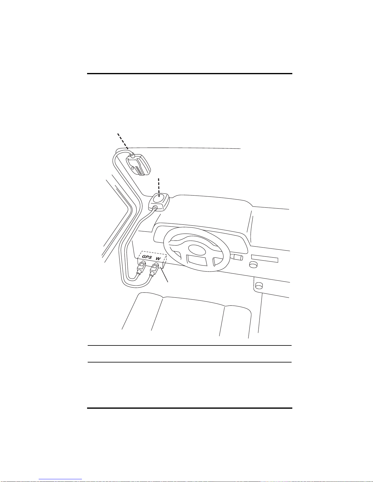
Installing the GPS/Wireless System
See the installation diagram below for correct placement and installation of all
the components in the GPS/Wireless System into a vehicle:
Note: If using a DriveRight 600 with a #8157 GPS Module, place the #8157 GPS antenna in the
same location as the #8128 GPS Module shown in the drawing above.
1. Place the GPS/Wireless Interface Module under the dashboard of the
vehicle, near the DriveRight 600Edevice or SmartCard On-Board Reader.
2. Secure the GPS/Wireless Interface Module in place using the provided
cable ties, two pieces of velcro tape, or two pieces of double-sided tape.
Cable must enter
unit from the top
GPS Module
#8128
Situated line-of-sight
to the sky
GPS/Wireless
Interface Module
#8127
Wireless
On-Board Module
#8129
Other manuals for DriveRight 8127
1
This manual suits for next models
2
Table of contents
Other DAVIS GPS manuals


