DIGITALCONTROLINCORPORATED
1 DigiTrak Falcon F5 iGPSSupplement A
Important Safety Instructions
Always operate your DigiTrak locating system properly to obtain accurate depth, pitch, roll, and locate
points. If you have any questions about the operation of the system, please contact DCI Customer Service
for assistance.
This document is a companion to your Falcon F5®guidance system operator's manual, which contains a
more thorough list of warnings regarding the potential for serious injury and death, work slowdowns, property
damage, and other hazards and warnings regarding the operation of horizontal drilling equipment. Please read
and understand your system operator's manual completely before operating the equipment described in this
manual.
The GPS receiver contained within DCI’s iGPS module was designed, by a third-party manufacturer, to
operate at up to sub-meter accuracy (according to the manufacturer’s design specification, limited to North
America, with WAAS correction). However, the accuracy of GNSS readings may in some cases be less
than the design specification due to a variety of factors such as the weather, obstruction from trees, buildings
and other impediments, interference from other signals or from solar activity, geographic location, inability to
read from a sufficient number of satellites for proper triangulation and error correction, whether the datum of
the GPS receiver matches up with the datum used by mapping tools such as Google Earth, other
environmental conditions, and other factors. Accordingly, DCI does not warrant or guarantee, and disclaims
liability for, the accuracy of GNSS data. It is also possible that satellite signals may be unavailable in some
cases. DCI does not assume responsibility for the operation or failure of satellite-based positioning systems
or the lack of availability of satellite-based positioning signals.
The iGPS module is designed to provide GNSS coordinates at up to sub-meter accuracy (in North America)
for your DataLog and convenient White Lining of the bore site. It is not intended for use as a bore planner, for
high-precision as-builts, or to guide the drill head during drilling. Accurate guidance of the drill head requires
accurate tracking of the transmitter locate points as discussed in the Falcon F5 guidance system operator's
manual.
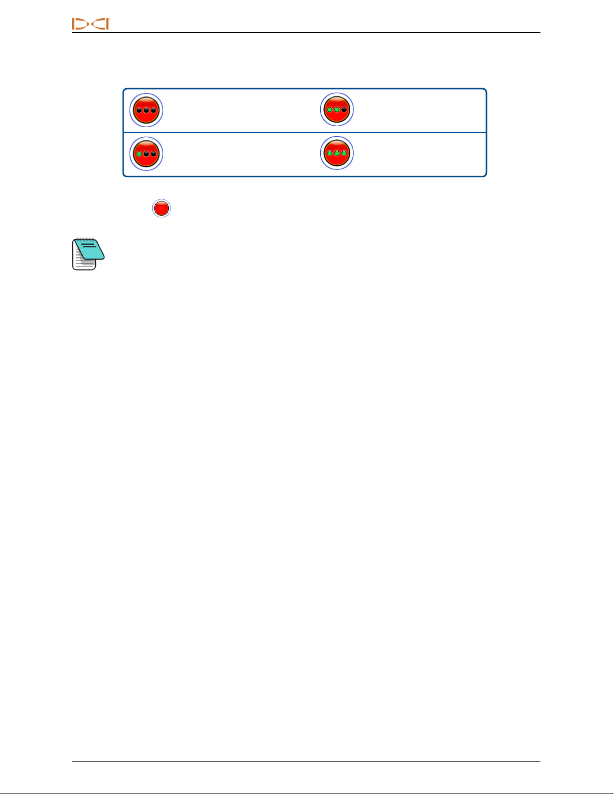
Monitor GNSS signal quality carefully using the iGPS LEDs and do not use GNSS readings unless at least
one of the three LED signal quality indicators is solid green (see GNSS Signal Quality on page 3).
Data logged, displayed, obtained, stored, and used by the Falcon F5, iGPS module, and LWD 3.04 is not
guaranteed to be accurate or complete. Human review and judgment is required. The accuracy and
completeness of data generated by HDD locating systems may be impacted by active or passive
interference and other environmental conditions, failure to calibrate or use the device properly, as well as a
variety of other factors.
The iGPS module is for use with DataLog files generated by a Falcon F5 receiver only. It is not compatible
with classic F5 or its DataLog files. Users of classic F5 or Eclipse receivers should continue using
LWD2.12.
Acronyms
GNSS Global Navigation Satellite System
GPS Global Positioning System
iGPS Integrated GPS
KML Keyhole Markup Language (used for Google Earth maps)
SBAS Satellite Based Augmentation System (increases GPSaccuracy)
WAAS Wide Area Augmentation System