SAFETY AND WARNINGS
1
IMPORTANT SAFETY INSTRUCTIONS!
Do not remove permanently affixed labels, warnings, or plates from the product. This may void the
warranty.
Please make this information available to the person installing the appliance as it could reduce your
installation costs.
Please leave these instructions with the appliance. Inform the customer to retain for future reference
and for the local inspectors’ use.
Failure to install the appliance correctly could invalidate any warranty or liability claims.
Only genuine replacement parts may be used for servicing the appliance. These are available from
your nearest Fisher & Paykel Service Center.
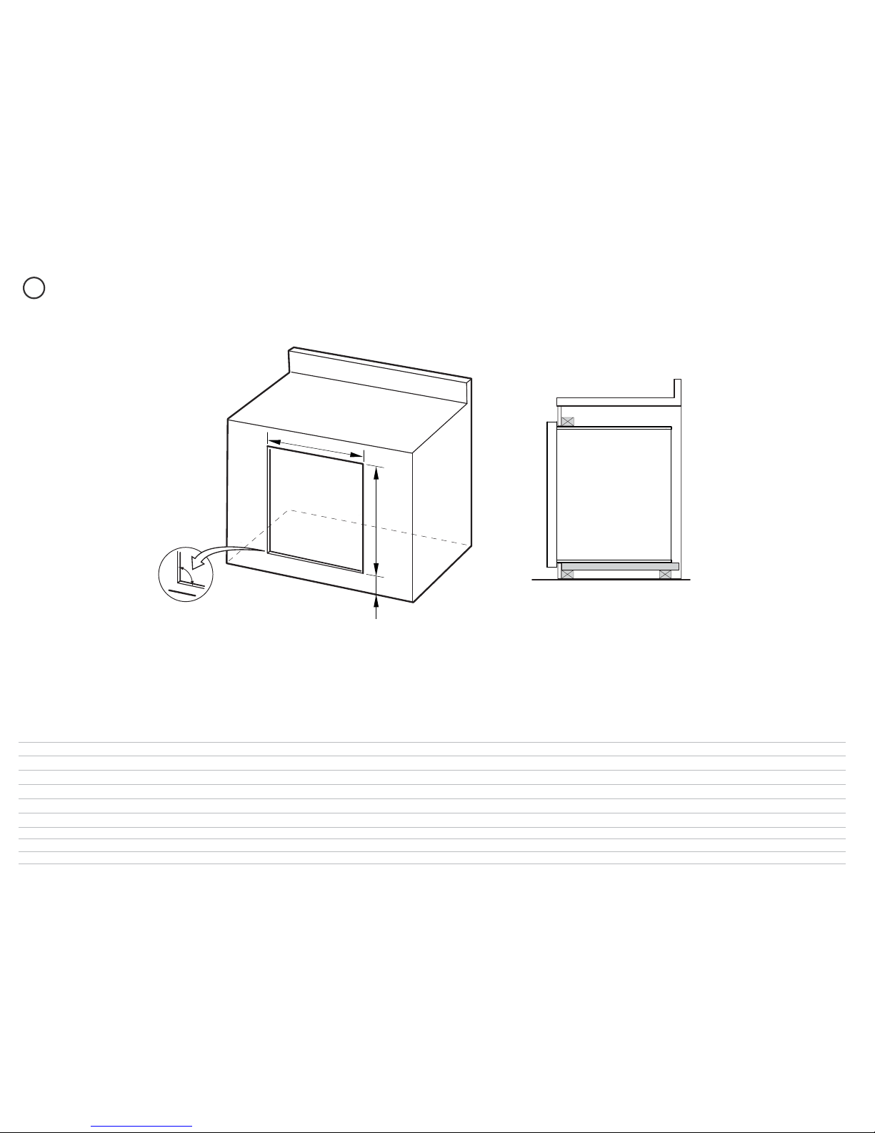
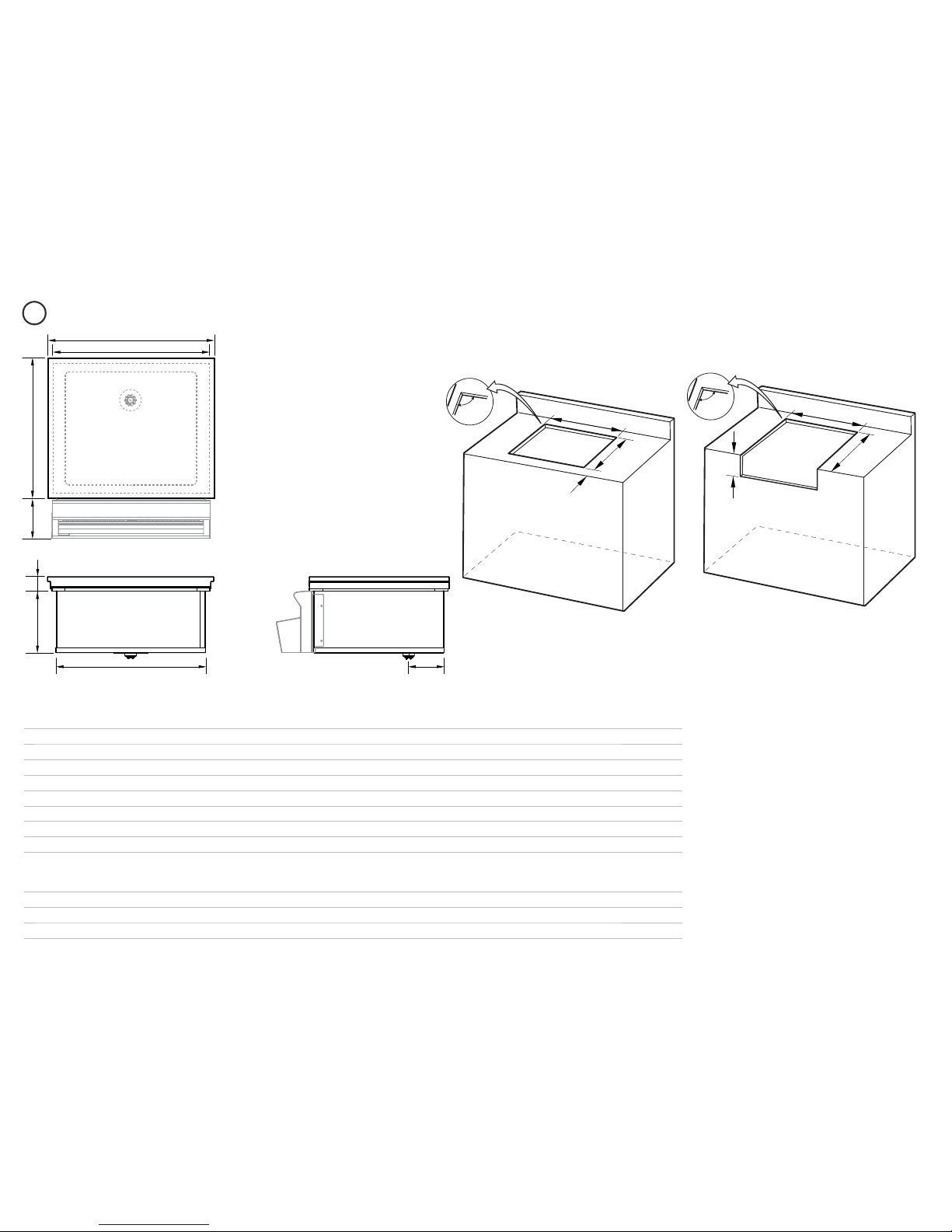
the countertop is square and level and no structural members interfere with space requirements
Do Not store or use gasoline or other flammable vapors and liquids inside or in the vicinity of this or
any other appliance.
An LP cylinder not connected for use shall not be stored inside or in the vicinity of this unit.
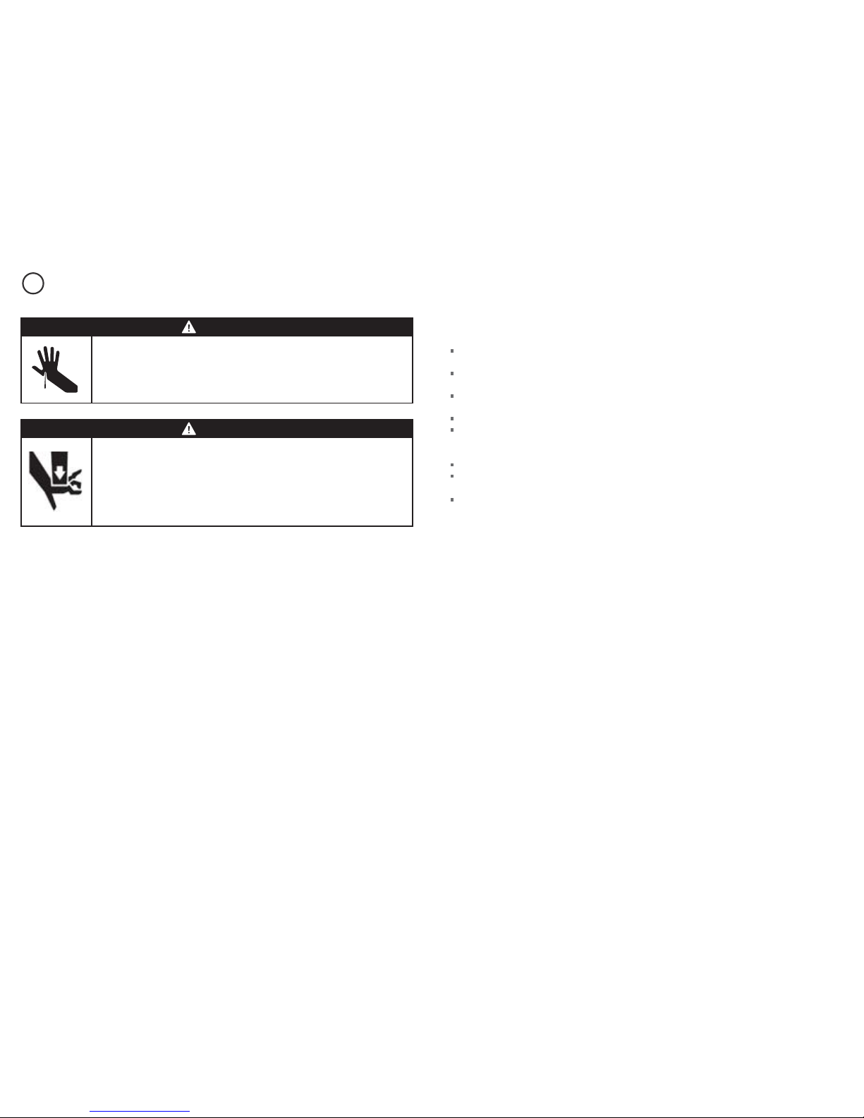
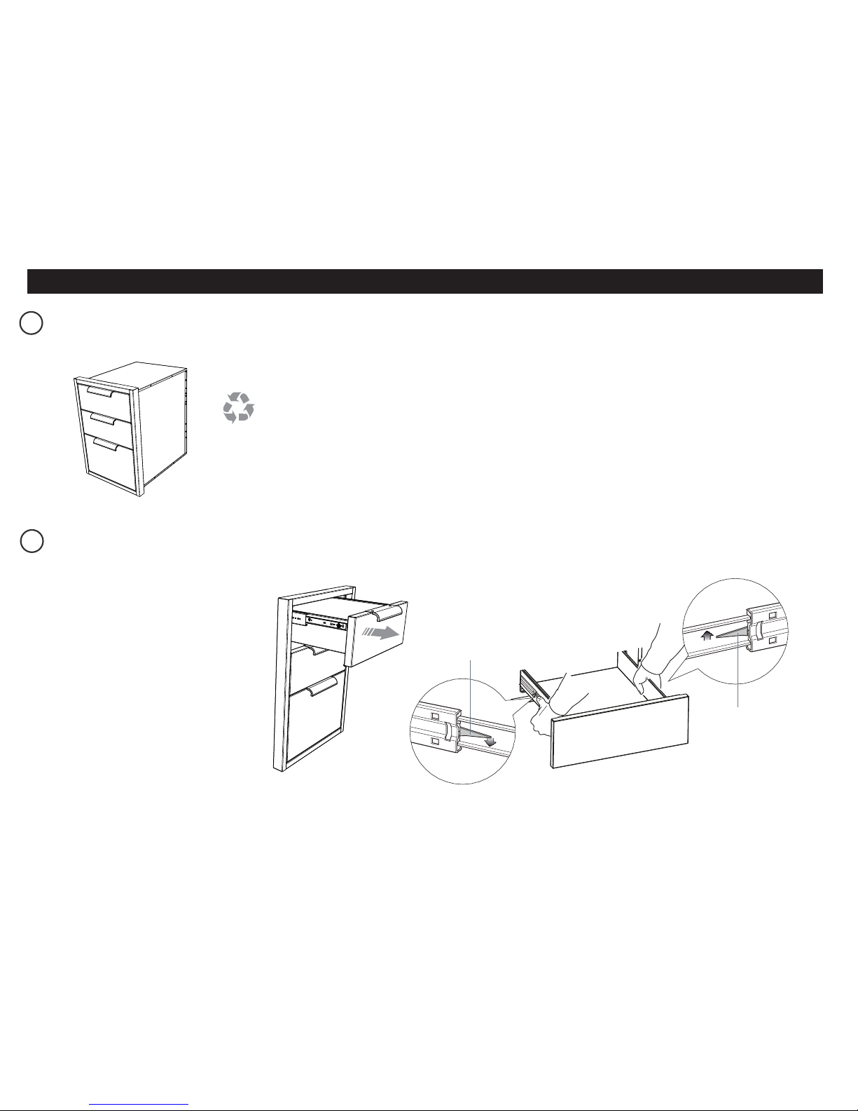
WARNING!
Cut hazard
Take care - panel edges are sharp.
Failure to use caution could result in injury or cuts.
WARNING!
Crush hazard
Closing drawers may cause injury to your hands or fingers.
Always close or open drawers using their handles.
Be sure to keep hands away from drawer edges when opening or closing
drawers.
Failure to use caution could result in injury or cuts.