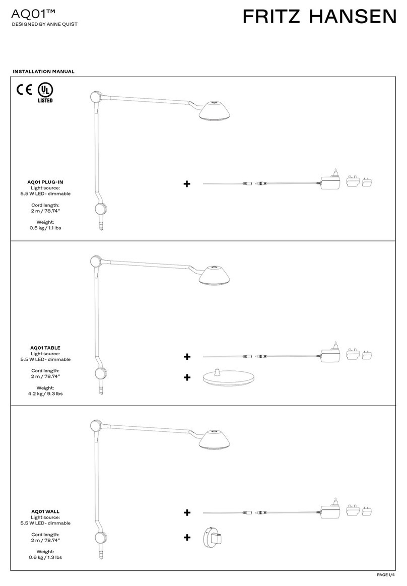
De Padova Nota Elisa Ossino User manual

Nota ––
Elisa Ossino
Schema di montaggio –– Assembly Instructions

32
Ferramenta e componenti in dotazione per lampada da terra:
Hardware and components supplied for floor lamp:
aBraccio lampada
Lamp arm
c1 Base (1 pz.)
Base (1 pc.)
c2 Base (1 pz.)
Base (1 pc.)
eVite M12x30 TSEI ( 1pz.)
Screw M12x30 TSEI (1 pc.)
gRipiani (1+1 pz.)
Small tops (1+1 pc.)
fChiave #8 (1 pz.)
Allen wrench #8 (1 pc.)
dAsta (1 pz.)
Bar (1 pc.)
bAlimentatore 2 canali (1 pz.)
Dual-output power supply (1 pc.)
Componenti in dotazione per lampada da terra e a parete:
Components supplied for floor and wall lamp:
IP42
Lampada da terra e da pare-
te per applicazioni civili.
– –
Costruita conforme alle norme di
riferimento del prodotto.
Floor/Wall lamp for personal
and civil use.
– –
Built in compliance with product
reference standards.
Attenzione:
– –
. Dopo aver tolto l’imballaggio
assicurarsi dell’integrità del pro-
dotto.
. In caso di dubbio non utilizzare
l’apparecchio e rivolgersi a per-
sonale professionalmente quali-
ficato.
. Tenere lontano dalla portata dei
bambini.
. Non tirare mai il cavo per scol-
legarlo dalla presa di corrente
elettrica.
. Non utilizzare con il cavo dan-
neggiato.
. In caso di guasto e/o malfun-
zionamento dell’apparecchio,
spegnerlo e non manometterlo.
. Per la riparazione rivolgersi sola-
mente a personale qualificato.
Please note:
– –
. After unpacking check the en-
tirety of the product.
. Should you have any doubts, do
not use the product and con-
tact a qualified professional.
. Keep out of the reach of chil-
dren.
. Never stretch the cable to dis-
connect it from the socket.
. Do not use the product if the
cable is damaged.
. If the product is broken and/or
damaged, switch it o and do
not tamper with it.
. For product repair, contact only
a qualified professional.
Ferramenta e componenti in dotazione per lampada da parete:
Hardware and components supplied for wall lamp:
hAsta a parete (1 pz.)
Wall Bar (1 pc.)
i
Supporto per il fissaggio
a parete
(2 pz.)
Bracket for wall
attachment (2 pc.
j Vite + tassello per muro (2 pz.)
Screw + wall anchor (2 pc.)
lGrano M3x4 (4 pz.)
Grub screw M3x4 (4 pc.)
k
Vite + tassello cartongesso (2 pz.)
Screw + plasterboard anchor (2 pc.)
mChiave #1.5 (1 pz.)
Allen Wrench #1.5 (1 pc.)
f1. braccio corto/short arm
f2. braccio medio/medium arm
f3. braccio lungo/long arm
Componenti UR/UR components
1 o 2 x 12W
Alimentazione/ Voltage:100/240V, 50-60Hz - Output 24 Vdc, 30W
f1.
f2.
f3.
0.3m

54
A
Montaggio della lampada da
terra:
1– –
Assemblare le basi (c1) e (c2)
con l’asta (d). Avvitare la vite (e)
usando la chiave a brugola (f).
A
2 – –
Allentare la ghiera di bloccag-
gio. Inserire il ripiano (g) dall’alto
dell’asta (d).
Fare attenzione al corretto posi-
zionamento del O-ring all’interno
della ghiera di bloccaggio.
A
Floor lamp assembly:
1 ––
Assembly the bases (c1) and (c2)
with the bar (d). Screw the screw
(e) using the allen wrench (f).
A
2 – –
Loosen the locking ring. Insert the
small top (g) from the top of the
bar (d).
Pay attention to the correct po-
sitioning of the O-ring inside the
locking ring.
LAMPADE A, B
– –
A. Lampada da terra con braccio
corto/medio.
B. Lampada da terra con braccio
corto/medio e due ripiani.
LAMPS A, B
– –
A. Floor lamp with short/medi-
um arm.
B. Floor lamp with short/medi-
um arm and two small tops.
B.A.
c1
c2
d
e
f
g
d
O.R.
d

76
A
3 – –
Per bloccare il ripiano (g) all’asta
(d) avvitare la ghiera di bloccag-
gio.
A
4 – –
Allentare la ghiera di bloccaggio.
Inserire il braccio lampada (a)
dall’alto dell’asta (d).
Fare attenzione al corretto posi-
zionamento del O-ring all’interno
della ghiera di bloccaggio.
Per bloccare il braccio lampada
(a) all’asta (d) avvitare la ghiera
di bloccaggio.
A
4 – –
Loosen the locking ring.
Insert the lamp arm (a) from the
top of the bar (d).
Pay attention to the correct po-
sitioning of the O-ring inside the
locking ring.
To block the lamp arm (a) to the
bar (d), please screw the locking
ring.
A
3 – –
To block the top(g) to the bar (d),
please screw the locking ring.
a
a
d
Attenzione:
– –
. Accertarsi che in prossimità del-
la foratura per il fissaggio non ci
siano attraversamenti elettrici o
idrici.
. È importante identificare il tipo
e la condizione della parete sulla
quale andrà installata la lampa-
da e verificarne la tenuta.
. Usare tasselli adeguati al tipo di
parete.
. De Padova non si assume al-
cuna responsabilità in caso di
danni dovuti a montaggio o uso
scorretto della lampada.
. In caso di incertezza sulla natu-
ra della parete, rivolgersi ad uno
specialista.
Please note:
– –
. Verify there are no plumbing
pipes or electric wires passing
where the light will be mounted.
. It is important to identify the
type, condition, and durability
of the wall where the lamp will
be installed.
. Use appropriate anchors based
on wall type.
. De Padova is not responsible for
damages caused by improper
assembly or misuse of the lamp.
. In case of uncertainty on wall
durability, contact a specialist.
d
g
LAMPADE C, D
– –
C. Lampada da parete con brac-
cio lungo.
D. Lampada da parete con brac-
cio lungo e medio.
LAMPS C, D
– –
C. Wall lamp with long arm.
D. Wall lamp with long and
medium arm.
D.C.

98
B
Montaggio della lampada a
parete
1 – –
Posizionare l’asta (h) e verificare
che sia perfettamente a piom-
bo. Segnare la posizione del foro
in alto e di quello in basso. La di-
stanza tra un foro e l’altro è di 190
cm ca.
B
2 – –
Drill the top hole. Insert the pin
(i) into the disk and screw the
screw(j/k).
B
2 – –
Eseguire il foro in alto. Inserire il
perno (i) nel disco e avvitare la
vite (j/k).
190 cm ca
B
Wall lamp assembly
1 – –
Position the bar (h); make sure
the bar is perpendicular to the
ground. Mark the position of top
and bottom holes. The distance
between the centres of two holes
is 190 cm about.
B
3 – –
Assembly the bar (h) on the up-
per bracket. Check if the axis of
the lower pin is in axis with the
hole below.
Drill the bottom hole. Insert the
pin into the disk and screw the
screw.
B
3 – –
Montare l’asta (h) sul supporto
per il fissaggio a parete superiore
e verificare che l’asse del perno in
basso corrisponda con il foro.
Eseguire il foro in basso. Inserire il
perno nel disco e avvitare la vite.
Dettaglio 2
Detail 2
Dettaglio 2
Detail 2
h
i
j
k
Dettaglio 1
Detail 1
Dettaglio 1
Detail 1
h

1110
a
h
m
h
B
5 – –
Svitare la vite usando la chiave a
brugola (m) e separare i due ele-
menti (h1) e (h2).
B
5 – –
Unscrew the screw using the allen
wrench (m) and separate the two
elements (h1) and (h2).
h1
h2
i
i
B
4 – –
Before assembly the lamp arm
check that the bar (h) can be as-
sembly on the brackets(i).
B
4 – –
Prima di montare il braccio lam-
pada verificare che sia possibile il
montaggio dell’asta (h) sui sup-
porti (i).
B
6 – –
Allentare la ghiera di bloccaggio.
Inserire il braccio lampada (a)
dall’alto dell’asta (h).
Fare attenzione al corretto posi-
zionamento del O-ring all’interno
della ghiera di bloccaggio.
Per bloccare il braccio lampada
(a) all’asta (h) avvitare la ghiera
di bloccaggio.
b
6 – –
Loosen the locking ring.
Insert the lamp arm (a) from the
top of the bar (h).
Pay attention to the correct po-
sitioning of the O-ring inside the
locking ring.
To block the lamp arm (a) to the
bar (h), please screw the locking
ring.
O.R.
h

1312
B
7 – –
Inserire (h1) in (h2) e avvitarli in-
sieme.
B
8 – –
Assemblare l’asta (h) sui supporti
per il fissaggio a parete (i). Avvi-
tare i grani (l) usando la chiave a
brugola (m).
B
7 – –
Insert (h1) into (h2) and screw
them together.
B
8 – –
Assembly the bar (h) on the
brackets (i). Screw the grub
screws (l) using the allen wrench
(m).
h1
h2
m
l
h
i
Istruzioni per l’Uso –– Instructions for use
Nota ––
Elisa Ossino

1514
b
C
Collegare la lampada all’ali-
mentatore 2 canali.
1 – –
Inserire il jack all’estremità del
cavo nell’apposito foro alla base
dell’alimentatore (b).
C
Connect the lamp to the du-
al-output power supply.
1 – –
Insert the jack at the end of the
cable into the hole in the base of
the power supply (b).
D
Per accendere le luci:
1 – –
Premendo l’interruttore, la luce si
accende alla massima intensità.
D
Switching on the lights:
1 – –
Pushing the switch, the light turns
on at maximum intensity.
E
Per dimmerare:
1 – –
Tenere premuto l’interruttore per
dimmerare la luminosità della
luce da massima a minima; e vi-
ceversa.
E
Dimming:
1 – –
Press and hold the switch to dim
the light brightness from maxi-
mum to minimum and vice-versa.
MAX
MAX
ON
ON
MIN
MIN
OFF
OFF
F
Per spegnere la luce:
1 – –
Premere l’interruttore per spe-
gnere la luce.
F
Switching o the light:
1 – –
Push the switch to switch o the
light.
A+B
A+B

_09.2018_
De Padova srl
Strada Padana Superiore 280A
20090 Vimodrone (Mi) –– Italy
T+39 02 27 43 97 95
www.depadova.com
Popular Home Lighting manuals by other brands
JONATHAN Y
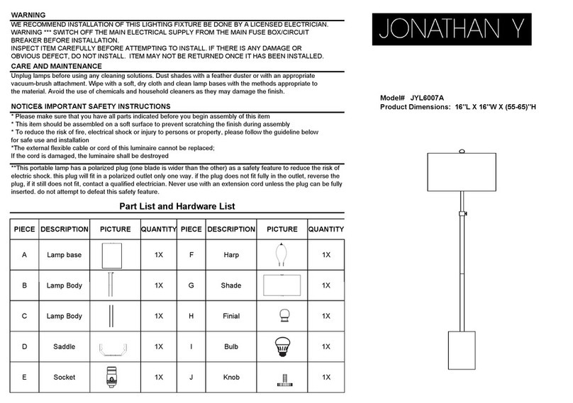
JONATHAN Y JYL6007A quick start guide
Philips
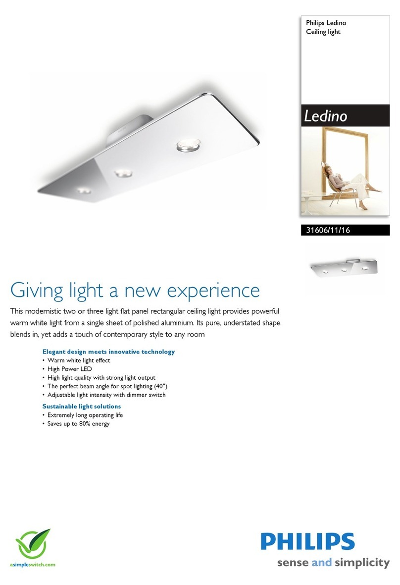
Philips Ledino 31606/11/16 Specifications
Safavieh Lighting
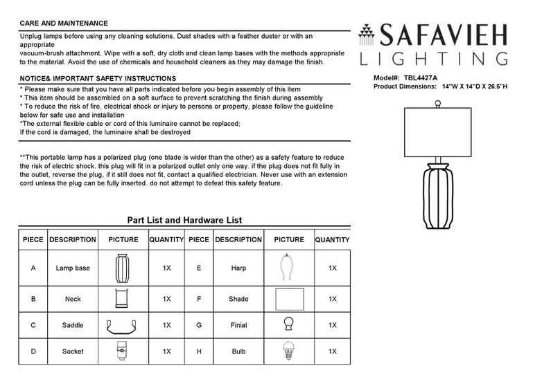
Safavieh Lighting CANDRI TBL4427A manual

Hunter
Hunter Bullet Spotlight Kit Owner's guide and installation manual

Philips
Philips 405441213 user manual
Philips
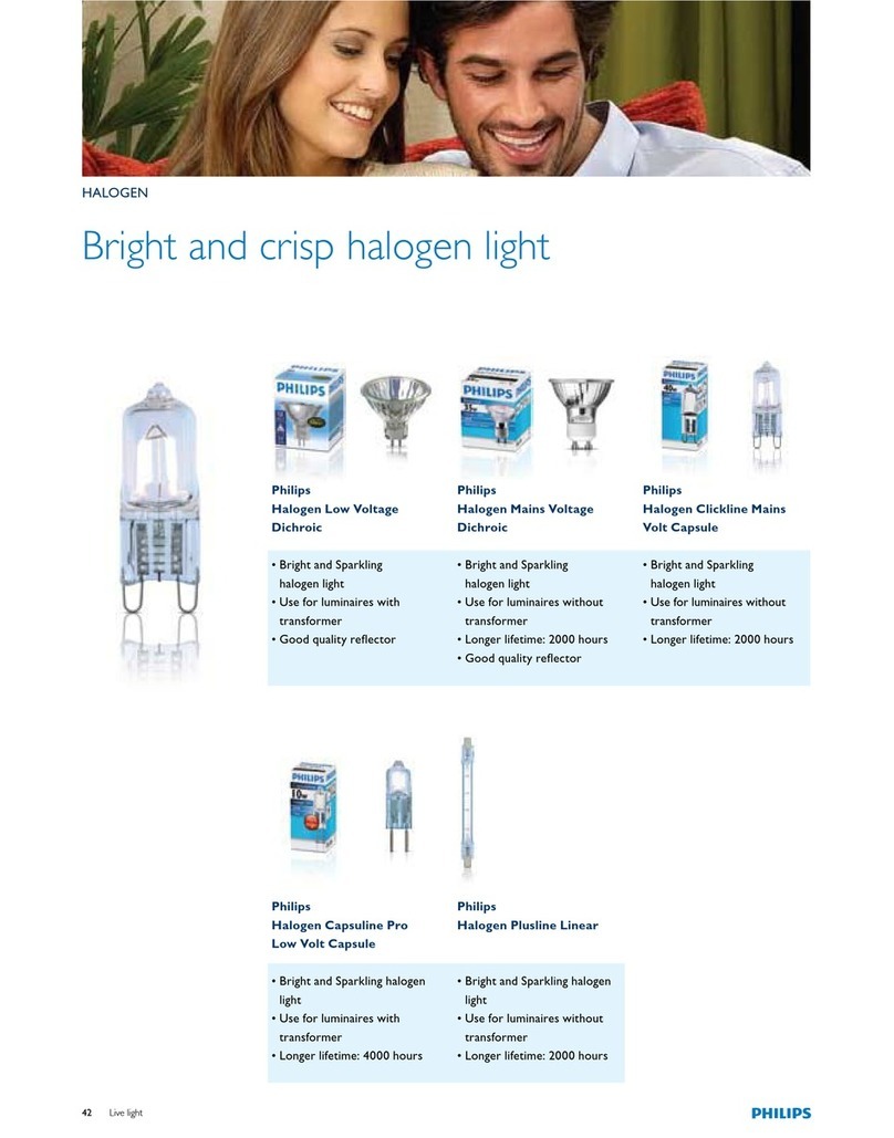
Philips Halogen Light Brochure & specs

