decaWave MDEK1001 User manual

MDEK1001 Kit User Manual
© Decawave 2017
OP-MDEK1001-System-User-Manual-1.0
MDEK1001 Kit User Manual
Module Development &
Evaluation Kit for the
DWM1001
Version 1.0
This document is subject to change without
notice

MDEK1001 Kit User Manual
© Decawave 2017
OP-MDEK1001-System-User-Manual-1.0
Page 2
TABLE OF CONTENTS
1INTRODUCTION..................................................................................................................... 8
1.1 OVERVIEW ...................................................................................................................................8
1.2 THE DWM1000 MODULE AND RTLS ..............................................................................................8
1.3 MAIN FEATURES OF THE MDEK1001 ..............................................................................................8
1.4 ANALYTICS ...................................................................................................................................8
1.5 MORE INFORMATION ....................................................................................................................8
2KIT CONTENTS....................................................................................................................... 9
2.1 SUPPLIED IN THE MDEK1001 BOX..................................................................................................9
2.2 ITEMS NOT INCLUDED..................................................................................................................10
2.3 AVAILABLE FROM THE DECAWAVE WEBSITE ....................................................................................11
3THE DWM1001-DEV DEVELOPMENT BOARD ........................................................................ 12
4THE DWM1001-DEV DEVELOPMENT BOARD LEDS ................................................................ 13
5SYSTEM SETUP & PREPARATION.......................................................................................... 14
5.1 PREPARE THE ANCHORS ...............................................................................................................14
5.2 PREPARE THE TAGS......................................................................................................................14
5.3 PREPARE THE ANDROID TABLET.....................................................................................................14
6SYSTEM CONFIGURATION EXAMPLES................................................................................... 15
6.1 1 ANCHOR +1TAG .....................................................................................................................15
6.2 CONFIGURE 4ANCHORS +8TAGS .................................................................................................15
6.3 11 ANCHORS +1TAG .................................................................................................................17
6.4 4 ANCHORS +7TAGS +1LISTENER ...............................................................................................18
7USAGE GUIDE...................................................................................................................... 19
7.1 OPEN THE ANDROID APPLICATION .................................................................................................19
7.2 START DEVICE DISCOVERY ............................................................................................................20
7.3 CREATE A NETWORK....................................................................................................................22
7.4 NETWORK DEVICE CONFIGURATION...............................................................................................23
7.4.1 ‘Networks & Devices page’..............................................................................................23
7.4.2 Remove a Device from a Network...................................................................................24
7.4.3 Device ‘Details’ page.......................................................................................................24
7.4.4 Tip: Label your Devices....................................................................................................26
7.4.5 Position the Anchors........................................................................................................27
7.5 SHOW LOCATION ........................................................................................................................28
7.6 SIDE MENU OPTIONS...................................................................................................................31
7.6.1 Position Log .....................................................................................................................31
7.6.2 Settings............................................................................................................................32
8LOGGING DATA VIA THE USB PORT...................................................................................... 34
8.1 INSTRUCTIONS ............................................................................................................................34
8.2 EXAMPLE OUTPUT.......................................................................................................................35
8.3 OTHER COMMANDS ....................................................................................................................35
9REFERENCES........................................................................................................................ 37
9.1 LISTING .....................................................................................................................................37
10 DOCUMENT HISTORY ....................................................................................................... 38

MDEK1001 Kit User Manual
© Decawave 2017
OP-MDEK1001-System-User-Manual-1.0
Page 3
10.1 REVISION HISTORY...................................................................................................................38
10.2 MAJOR CHANGES ....................................................................................................................38
11 ABOUT DECAWAVE.......................................................................................................... 39
LIST OF TABLES
TABLE 1: KIT CONTENTS ...............................................................................................................................9
TABLE 2: ALSO REQUIRED OR USEFUL,NOT PROVIDED IN THE BOX....................................................................10
TABLE 3: AVAILABLE ON THE DECAWAVE WEBSITE..........................................................................................11
TABLE 4: TABLE OF REFERENCES..................................................................................................................37
TABLE 5: DOCUMENT HISTORY ....................................................................................................................38
LIST OF FIGURES
FIGURE 1: FRONT VIEW OF THE DWM1001-DEV MODULE DEVELOPMENT BOARD............................................12
FIGURE 2: FRONT VIEW OF THE DWM1001-DEV MODULE DEVELOPMENT BOARD............................................13
FIGURE 3: POSITIONING OF ANCHORS AND TAGS ............................................................................................14
FIGURE 4: SYSTEM CONFIGURATION OPTION:1ANCHOR,1TAG ......................................................................15
FIGURE 5: SYSTEM CONFIGURATION OPTION:4ANCHORS,8TAGS ...................................................................15
FIGURE 6: SYSTEM CONFIGURATION OPTION:4ANCHORS,8TAGS &PC LOGGING .............................................16
FIGURE 7: SYSTEM CONFIGURATION OPTION:11 ANCHORS,1TAG...................................................................17
FIGURE 8: SYSTEM CONFIGURATION OPTION:4ANCHORS,7TAGS,1LISTENER ..................................................18
FIGURE 9: DECAWAVE DRTLS MANAGER HOME SCREEN ................................................................................19
FIGURE 10: DEVICE DISCOVERY SCREEN ........................................................................................................20
FIGURE 11: DEVICE DISCOVERY SCREEN –SELECT MULTIPLE DEVICES................................................................21
FIGURE 12: NAME NETWORK SCREEN ..........................................................................................................22
FIGURE 13: NETWORKS&DEVICES LIST.........................................................................................................22
FIGURE 14: NETWORK DETAILS SCREEN ........................................................................................................23
FIGURE 15:NETWORK DETAILS SCREEN:DEVICE INFORMATION........................................................................23
FIGURE 16: NETWORK DETAILS SCREEN:EXPANDED DEVICE PARAMETERS .........................................................24
FIGURE 17: DEVICE DETAILS SCREEN –ANCHOR &TAG...................................................................................25
FIGURE 18: AUTO-POSITIONING SCREEN.......................................................................................................27
FIGURE 19: AUTO-POSITIONING:ANCHOR POSITIONING RULES .......................................................................28
FIGURE 20: GRID SCREEN –ANCHOR PLACEMENT &TAG TRACKING .................................................................29
FIGURE 21: GRID SCREEN –ANCHOR SELECTION ............................................................................................29
FIGURE 22: DECAWAVE DRTLS MANAGER SIDE MENU SCREEN .......................................................................31
FIGURE 23: DECAWAVE DRTLS MANAGER POSITION LOG...............................................................................32
FIGURE 24: DECAWAVE DRTLS MANAGER SETTINGS SCREEN ..........................................................................33
MDEK1001 Kit User Manual
© Decawave 2017
OP-MDEK1001-System-User-Manual-1.0
Page 4
DOCUMENT INFORMATION
Disclaimer
Decawave reserves the right to change product specifications without notice. As far as possible changes to
functionality and specifications will be issued in product specific errata sheets or in new versions of this
document. Customers are advised to check with Decawave for the most recent updates on this product.
Copyright © 2017 Decawave Ltd.
LIFE SUPPORT POLICY
Decawave products are not authorized for use in safety-critical applications (such as life support) where a
failure of the Decawave product would reasonably be expected to cause severe personal injury or death.
Decawave customers using or selling Decawave products in such a manner do so entirely at their own risk
and agree to fully indemnify Decawave and its representatives against any damages arising out of the use of
Decawave products in such safety-critical applications.
Caution! ESD sensitive device. Precaution should be used when handling the device in order
to prevent permanent damage.
REGULATORY APPROVALS
This MDEK1001 evaluation kit based on Decawave’s DW1000 IC & DWM1001 module is intended
solely for use by competent engineering personnel for the purposes of evaluating the use of
Decawave’s DW1000 IC & DWM1001 module in wireless location and communications systems.
The MDEK1001, as supplied from Decawave, has not been certified for use in any particular
geographic region by any regulatory body governing radio emissions in such regions.
The MDEK1001 is supplied under the following conditions: -
The distribution and sale of the MDEK1001 is intended solely for use in future development
of devices which may be subject to regulations or other authority governing radio emission.
This MDEK1001 may not be resold by users for any purpose.
The MDEK1001 as supplied by Decawave may not be incorporated directly into user
devices or products unless such products undergo the appropriate certification.
Operation of the MDEK1001 in the development of future devices is at the discretion of the
user and the user bears all responsibility for any compliance with regulations laid down by
the authority governing radio emissions in the user’s jurisdiction.
All products developed by the user incorporating the DW1000 or DWM1001 must be approved by
the relevant authority governing radio emissions in a jurisdiction prior to the marketing or sale of
such products in that jurisdiction. User bears all responsibility for obtaining such approval.
If the user has obtained the MDEK1001 for any purpose other than those listed above the user
should return the MDEK1001 to the supplier immediately.
FCC NOTICE: This kit is designed to allow (i) product developers to evaluate electronic
components, circuitry, or software associated with the kit to determine whether to incorporate such
items in a finished product and (ii) software developers to write software applications for use with
the end product. This kit is not a finished product and when assembled may not be resold or
otherwise marketed unless all required FCC equipment authorizations are first obtained. Operation
is subject to the conditions that this device not cause harmful interference to licensed radio stations
and that this device accept harmful interference. Unless the assembled kit is designed to operate
under Part 15, Part 18 or Part 95 of the FCC Rules, the operator of the kit must operate under the
authority of an FCC license holder or must secure an experimental authorization under Part 5 of the
FCC Rules.

MDEK1001 Kit User Manual
© Decawave 2017
OP-MDEK1001-System-User-Manual-1.0
Page 5
DISCLAIMER
(1) This Disclaimer applies to the software provided by Decawave Ltd. (“Decawave”) in
support of its DWM1001 module product (“Module”) all as set out at clause 3 herein
(“Decawave Software”).
(2) Decawave Software is provided in two ways as follows: -
(a) pre-loaded onto the Module at time of manufacture by Decawave (“Firmware”);
(b) supplied separately by Decawave (“Software Bundle”).
(3) Decawave Software consists of the following components (a) to (d) inclusive:
(a) The Decawave Positioning and Networking Stack (“PANS”), available as a
library accompanied by source code that allows a level of user customisation.
The PANS software is pre-installed and runs on the Module as supplied, and
enables mobile “tags”, fixed “anchors” and “gateways” that together deliver the
DWM1001 Two-Way-Ranging Real Time Location System (“DRTLS”)
Network.
(b) The Decawave DRTLS Manager which is an Android™ application for
configuration of DRTLS nodes (nodes based on the Module) over Bluetooth™.
(c) The Decawave DRTLS Gateway Application which supplies a gateway
function (on a Raspberry Pi ®) routing DRTLS location and sensor data traffic
onto an IP based network (e.g. LAN), and consists of the following components:
DRTLS Gateway Linux Kernel Module
DRTLS Gateway Daemon
DRTLS Gateway MQTT Broker
DRTLS Gateway Web Manager
(d) Example Host API functions, also designed to run on a Raspberry Pi, which
show how to drive the Module from an external host microprocessor.
(4) The following third party components are used by Decawave Software and are
incorporated in the Firmware or included in the Software Bundle as the case may be: -
(a) The PANS software incorporates the Nordic SoftDevice S132-SD-v3 version
3.0.0 (production) which is included in the Firmware and is also included in the
Software Bundle;
(b) The PANS software uses the eCos RTOS which is included in the Software
Bundle. The eCos RTOS is provided under the terms of an open source licence
which may be found at: http://ecos.sourceware.org/license-overview.html;
(c) The PANS software uses an open source CRC-32 function from FreeBSD which
is included in the Software Bundle. This CRC-32 function is provided under the
terms of the BSD licence which may be found at:
https://github.com/freebsd/freebsd/blob/386ddae58459341ec56760470780581
4a2128a57/COPYRIGHT;

MDEK1001 Kit User Manual
© Decawave 2017
OP-MDEK1001-System-User-Manual-1.0
Page 6
(d) The Decawave DRTLS Manager application uses open source software which
is provided as source code in the Software Bundle. This open source software
is provided under the terms of the Apache Licence v2.0 which may be found at
http://www.apache.org/licenses/LICENSE-2.0;
(e) The Decawave DRTLS Gateway Application uses the following third party
components: -
(i) The Linux Kernel which is provided as source code in the Software
Bundle. The Linux Kernel is provided under the terms of the GPLv2
licence which may be found at: https://www.gnu.org/licenses/old-
licenses/gpl-2.0.en.html and as such the DWM1001 driver component
of the DRTLS Gateway Application is provided under the same license
terms;
(ii) The three.js JavaScript library, the downloadable version of which is
available here https://threejs.org/, is provided under the terms of the MIT
Licence which may be found at https://opensource.org/licenses/MIT.
Items (a), (b), (c), (d) and (e) in this section 4 are collectively referred to as the “Third
Party Software”
(5) Decawave Software incorporates source code licensed to Decawave by Leaps s.r.o., a
supplier to Decawave, which is included in the Firmware and the Software Bundle in
binary and/or source code forms as the case may be, under the terms of a license
agreement entered into between Decawave and Leaps s.r.o.
(6) Decawave hereby grants you a free, non-exclusive, non-transferable, worldwide license
without the right to sub-license to design, make, have made, market, sell, have sold or
otherwise dispose of products incorporating Decawave Software, to modify Decawave
Software or incorporate Decawave Software in other software and to design, make,
have made, market, sell, have sold or otherwise dispose of products incorporating such
modified or incorporated software PROVIDED ALWAYS that the use by you of Third
Party Software as supplied by Decawave is subject to the terms and conditions of the
respective license agreements as set out at clause 4 herein AND PROVIDED ALWAYS
that Decawave Software is used only in systems and products based on Decawave
semiconductor products. NO OTHER LICENSE, EXPRESS OR IMPLIED, BY
ESTOPPEL OR OTHERWISE TO ANY OTHER DECAWAVE INTELLECTUAL
PROPERTY RIGHT, AND NO LICENSE TO ANY THIRD PARTY TECHNOLOGY
OR INTELLECTUAL PROPERTY RIGHT, IS GRANTED HEREIN, including but
not limited to any patent right, copyright, mask work right, or other intellectual property
right relating to any combination, machine, or process in which Decawave
semiconductor products or Decawave Software are used.
(7) Downloading, accepting delivery of or using Decawave Software indicates your
agreement to the terms of (i) the license grated at clause 6 herein, (ii) the terms of this
Disclaimer and (iii) the terms attaching to the Third Party Software. If you do not agree
with all of these terms do not download, accept delivery of or use Decawave Software.
(8) Decawave Software is solely intended to assist you in developing systems that
incorporate Decawave semiconductor products. You understand and agree that you
remain responsible for using your independent analysis, evaluation and judgment in
designing your systems and products. THE DECISION TO USE DECAWAVE

MDEK1001 Kit User Manual
© Decawave 2017
OP-MDEK1001-System-User-Manual-1.0
Page 7
SOFTWARE IN WHOLE OR IN PART IN YOUR SYSTEMS AND PRODUCTS
RESTS ENTIRELY WITH YOU AND DECAWAVE ACCEPTS NO LIABILTY
WHATSOEVER FOR SUCH DECISION.
(9) DECAWAVE SOFTWARE IS PROVIDED "AS IS". DECAWAVE MAKES NO
WARRANTIES OR REPRESENTATIONS WITH REGARD TO DECAWAVE
SOFTWARE OR USE OF DECAWAVE SOFTWARE, EXPRESS, IMPLIED OR
STATUTORY, INCLUDING ACCURACY OR COMPLETENESS. DECAWAVE
DISCLAIMS ANY WARRANTY OF TITLE AND ANY IMPLIED WARRANTIES
OF MERCHANTABILITY, FITNESS FOR A PARTICULAR PURPOSE AND NON-
INFRINGEMENT OF ANY THIRD PARTY INTELLECTUAL PROPERTY
RIGHTS WITH REGARD TO DECAWAVE SOFTWARE OR THE USE THEREOF.
(10) DECAWAVE SHALL NOT BE LIABLE FOR AND SHALL NOT DEFEND OR
INDEMNIFY YOU AGAINST ANY THIRD PARTY INFRINGEMENT CLAIM
THAT RELATES TO OR IS BASED ON DECAWAVE SOFTWARE OR THE USE
OF DECAWAVE SOFTWARE. IN NO EVENT SHALL DECAWAVE BE LIABLE
FOR ANY ACTUAL, SPECIAL, INCIDENTAL, CONSEQUENTIAL OR
INDIRECT DAMAGES, HOWEVER CAUSED, INCLUDING WITHOUT
LIMITATION TO THE GENERALITY OF THE FOREGOING, LOSS OF
ANTICIPATED PROFITS, GOODWILL, REPUTATION, BUSINESS RECEIPTS
OR CONTRACTS, COSTS OF PROCUREMENT OF SUBSTITUTE GOODS OR
SERVICES; LOSS OF USE, DATA, OR PROFITS; OR BUSINESS
INTERRUPTION), LOSSES OR EXPENSES RESULTING FROM THIRD PARTY
CLAIMS. THESE LIMITATIONS WILL APPLY REGARDLESS OF THE FORM
OF ACTION, WHETHER UNDER STATUTE, IN CONTRACT OR TORT
INCLUDING NEGLIGENCE OR ANY OTHER FORM OF ACTION AND
WHETHER OR NOT DECAWAVE HAS BEEN ADVISED OF THE POSSIBILITY
OF SUCH DAMAGES, ARISING IN ANY WAY OUT OF DECAWAVE
SOFTWARE OR THE USE OF DECAWAVE SOFTWARE.
(11) You acknowledge and agree that you are solely responsible for compliance with all
legal, regulatory and safety-related requirements concerning your products, and any use
of Decawave Software in your applications, notwithstanding any applications-related
information or support that may be provided by Decawave.
(12) Decawave reserves the right to make corrections, enhancements, improvements and
other changes to its software, including Decawave Software, at any time.
Mailing address: Decawave Ltd.,
Adelaide Chambers,
Peter Street,
Dublin D08 T6YA
IRELAND.
Copyright (c) 15 November 2017 by Decawave Limited. All rights reserved. All trademarks
are the property of their respective owners

MDEK1001 Kit User Manual
© Decawave 2017
OP-MDEK1001-System-User-Manual-1.0
Page 8
1 INTRODUCTION
1.1 Overview
The MDEK1001 is a development and evaluation kit that allows the user to evaluate the
Decawave DWM1001 module.
MDEK1001 stands for Module Development & Evaluation Kit for the Decawave DWM1001.
1.2 The DWM1000 module and RTLS
The DWM1001 is a module product that comes complete with firmware to allow system
developers to quickly implement an RTLS to suit their particular end application, or add
RTLS capability to an existing system. The module may be configured to behave as an
“anchor” one of the fixed nodes in the system or a “tag” one of the mobile located nodes in
the system. The module configuration may be achieved either via Bluetooth using the
companion application (Decawave DRTLS Manager) or via an SPI or UART connection from
an external host.
The module incorporates Decawave’s DW1000 UWB transceiver which the module’s on-
board firmware drives to implement the network of anchor nodes and perform the two-way
ranging exchanges with the tag nodes enabling each tag to compute its own location.
The module also incorporates the Nordic Semiconductor NRF52832 IC providing the
Bluetooth connectivity used for configuration and the microprocessor that runs the firmware
which drives the DW1000 and provides the RTLS enabling functionality. A more complete
description of this may be found in DWM1001 System Overview.
The module is typically mounted on a PCB, such as the DWM1001-DEV product. The
MDEK1001 kit provides 12 DWM1001 modules already mounted on “development” boards
enabling system developers evaluate the product and/or begin their system development
before embarking on their own designs.
1.3 Main Features of the MDEK1001
Out-of-the-box wireless Real-Time Location System (RTLS), including anchors and
tags (and gateway support) without designing any hardware or writing a single line of
code
Quick and easy installation and setup
12 RTLS units (DWM1001-DEV) configurable as 4 to 11 anchors and 1 to 8 tags
Configure and control the module via APIs via UART/SPI/Bluetooth
Modify the module firmware to customise your application
Configuration & location application for tablets/smartphones (Android 6.0 or 7.0)
Configuration & location web client (Q1 2018)
1.4 Analytics
Note: the Android application (Decawave DRTLS Manager) reports application crash
diagnostics back to Decawave (and design partner) in order to improve future versions.
1.5 More Information
More information about the MDEK1001, the DWM1001-DEV Development Board, the
DWM1001 module and the DW1000 IC can be found on the Decawave website.
MDEK1001 Kit User Manual
© Decawave 2017
OP-MDEK1001-System-User-Manual-1.0
Page 9
2 KIT CONTENTS
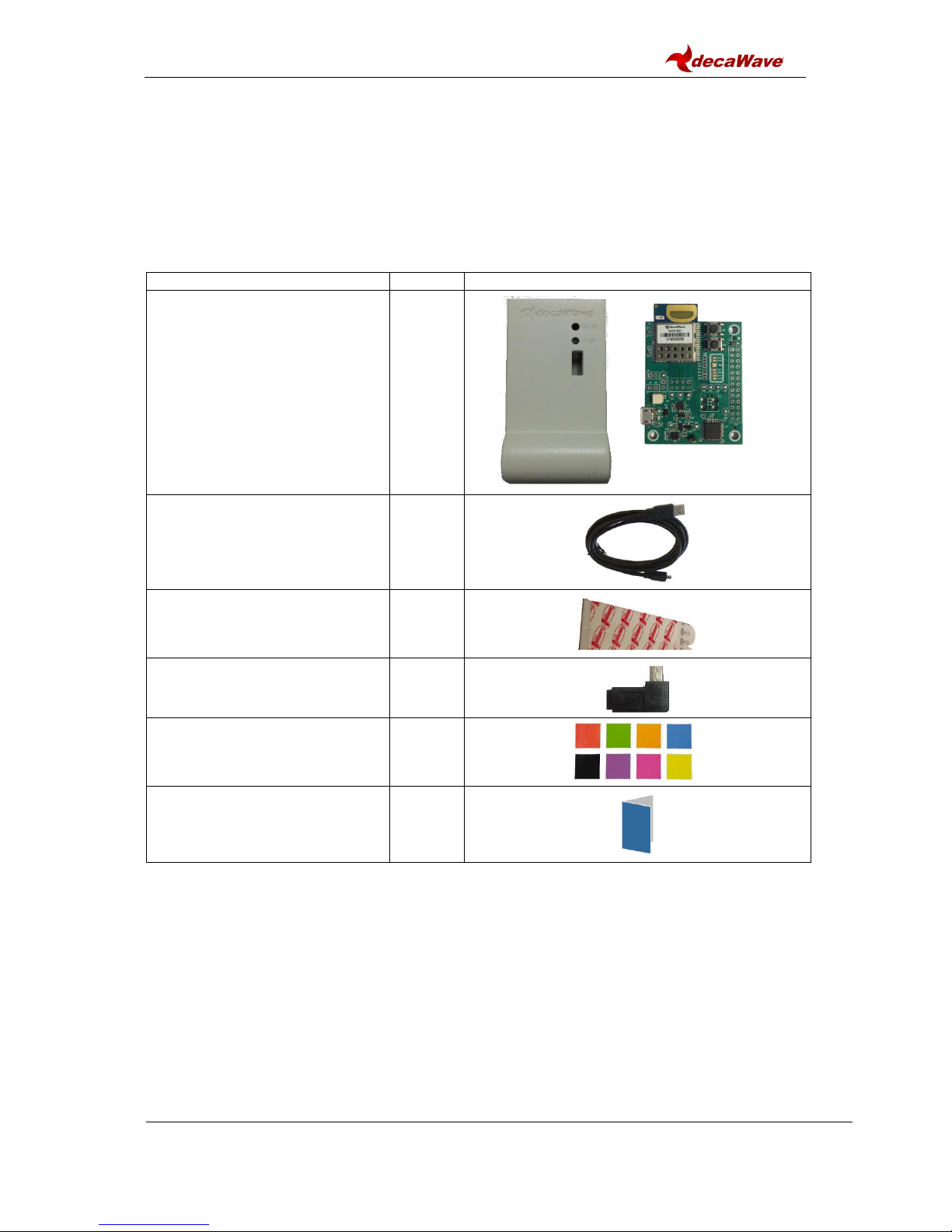
2.1 Supplied in the MDEK1001 Box
The following items are included in the box.
Table 1: Kit Contents
Description
Quantity
Image
RTLS units
- Containing DWM1001-DEV
Development Boards
12
1.0 m USB Cable
1
Adhesive Pads
8
Right-Angled USB Connectors
4
Colored Stickers
8
Quick Start Guide
1
MDEK1001 Kit User Manual
© Decawave 2017
OP-MDEK1001-System-User-Manual-1.0
Page 10
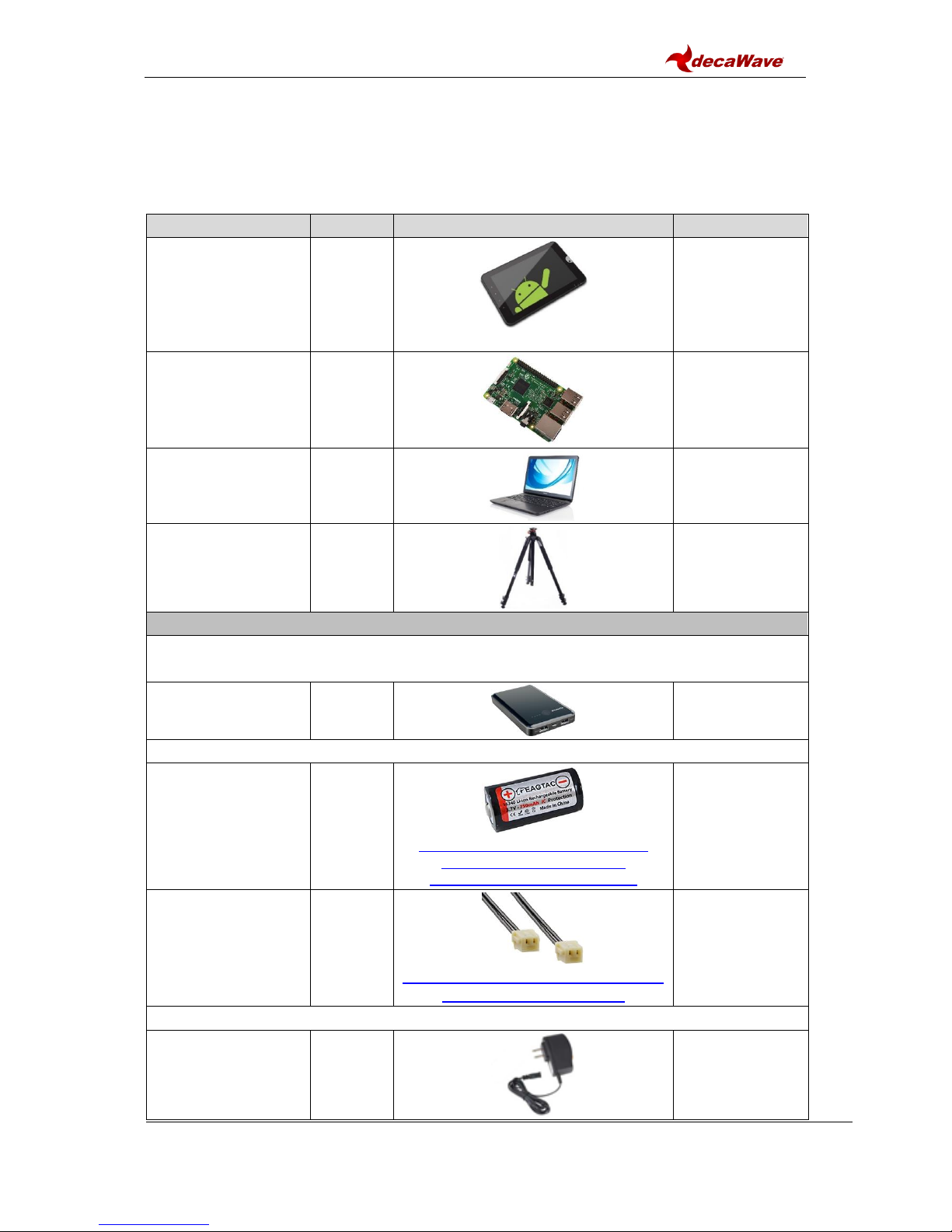
2.2 Items Not Included
Other items, not included in the box are listed below.
Table 2: Also Required or Useful, Not Provided in the Box
Description
Quantity
Image
Notes
Android Tablet or
Smartphone
(to run the
configuration/location
application)
1
OS should be Android 6.x or 7.x
Required
Raspberry PI 3, Model
B
1
To act as a
gateway
(Q1 2018)
PC
(Windows 7 or 10)
1
For visualisation
of gateway data
(Q1 2018)
Tripods
(to mount the anchors)
4+
Useful
Options for Powering RTLS Units
Note: for long duration tests it is recommended to power anchors from mains or
larger power banks rather than low capacity batteries
USB Battery
OR
3.7V RCR123a or
16340 rechargeable
battery.
Note: overcharge
protection not
necessary.
https://www.amazon.com/Eagletac-
16340-RCR123A-Protected-
Rechargeable/dp/B00YAVB7U2
Connect mobile
battery to board via
mating battery
connector:
JST:
A02SR02SR30K51B
https://www.digikey.com/products/en
?keywords=455-3009-ND
OR
Power Adaptor to USB
or
PC to USB
(USB micro type B)
MDEK1001 Kit User Manual
© Decawave 2017
OP-MDEK1001-System-User-Manual-1.0
Page 11
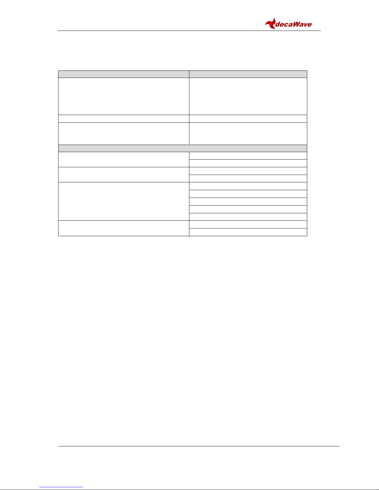
2.3 Available from the Decawave Website
Table 3: Available on the Decawave Website
Description
Details
Decawave DRTLS Manager:
tablet/smartphone application
Android application file (.apk) for
configuration & location
(Note: configuration and logging of
locations can also be done on a PC
terminal)
PC Configuration/Location Application
Available: Q1 2018
Links To
Battery connectors
Raspberry PI
Raspberry PI connectors
Documentation
MDEK1001: Module Development &
Evaluation Kit for the Decawave DWM1001
MDEK1001 System User Manual
MDEK1001 Quick Start Guide
DWM1001-DEV: DWM1001 Module
Development Board
DWM1001-DEV Product Brief
DWM1001-DEV Hardware Datasheet
DWM1001: Module
DWM1001 Product Brief
DWM1001 Hardware Datasheet
DWM1001 System Overview
DWM1001 Firmware User Guide
DWM1001 API Guide
DW1000: IC
DW1000 Datasheet
DW1000 User Manual
MDEK1001 Kit User Manual
© Decawave 2017
OP-MDEK1001-System-User-Manual-1.0
Page 12
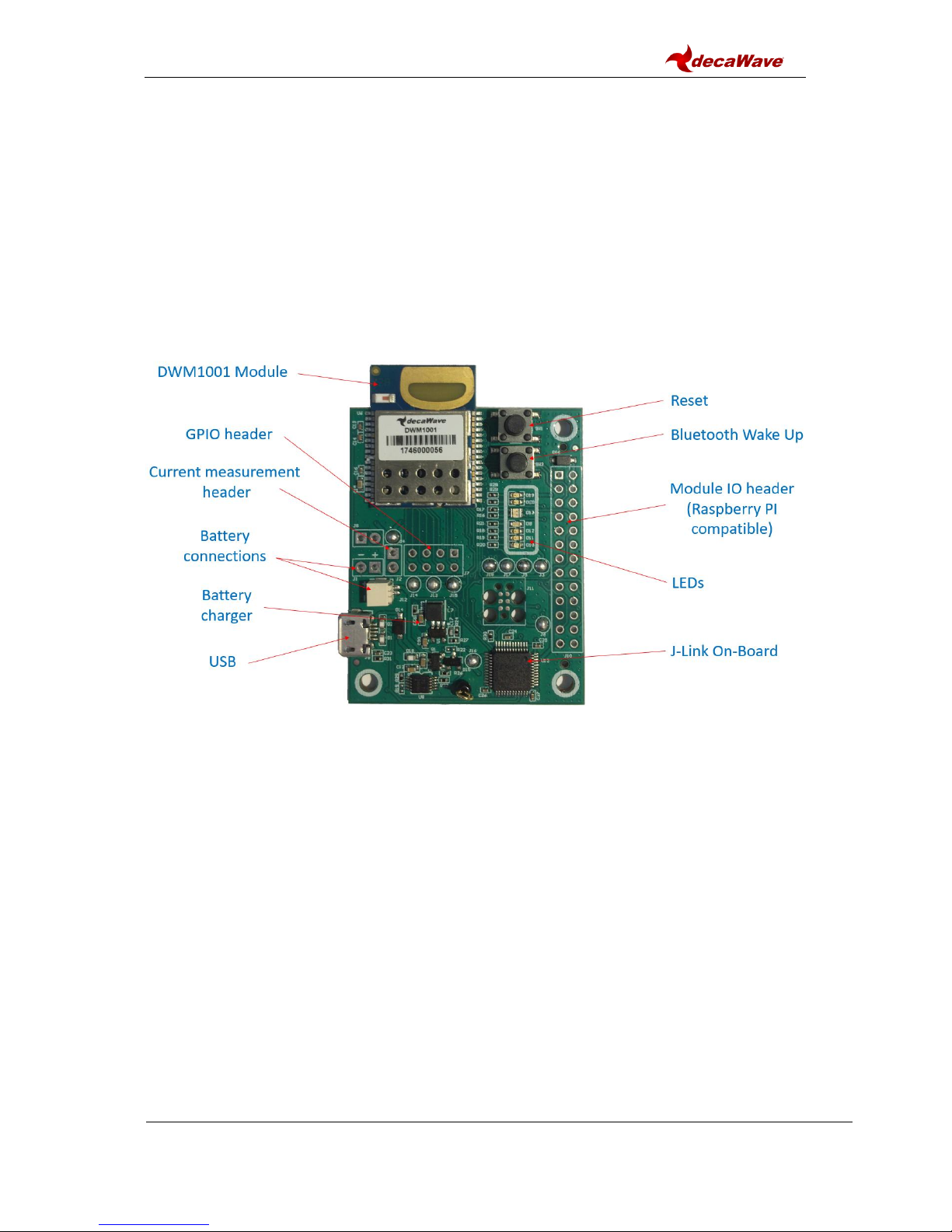
3 THE DWM1001-DEV DEVELOPMENT BOARD
The image below shows the key features of a DWM1001-DEV development board.
The key features of this board are:
Decawave DWM1001 module soldered in place
Li-Po/Li-ion battery charging circuit
Connectors:
oBattery connector for Li-Ion or Li-Po rechargeable batteries, or non-
rechargeable batteries
oUSB connector for power, flashing and debug
oRaspberry PI connector footprint for expansion and host interface control
Figure 1: Front View of the DWM1001-DEV Module Development Board

MDEK1001 Kit User Manual
© Decawave 2017
OP-MDEK1001-System-User-Manual-1.0
Page 13
4 THE DWM1001-DEV DEVELOPMENT BOARD LEDS
Figure 2: Front View of the DWM1001-DEV Module Development Board
NOTE: Details of the functions of these LEDs are given in the DWM1001-DEV Datasheet.
MDEK1001 Kit User Manual
© Decawave 2017
OP-MDEK1001-System-User-Manual-1.0
Page 14
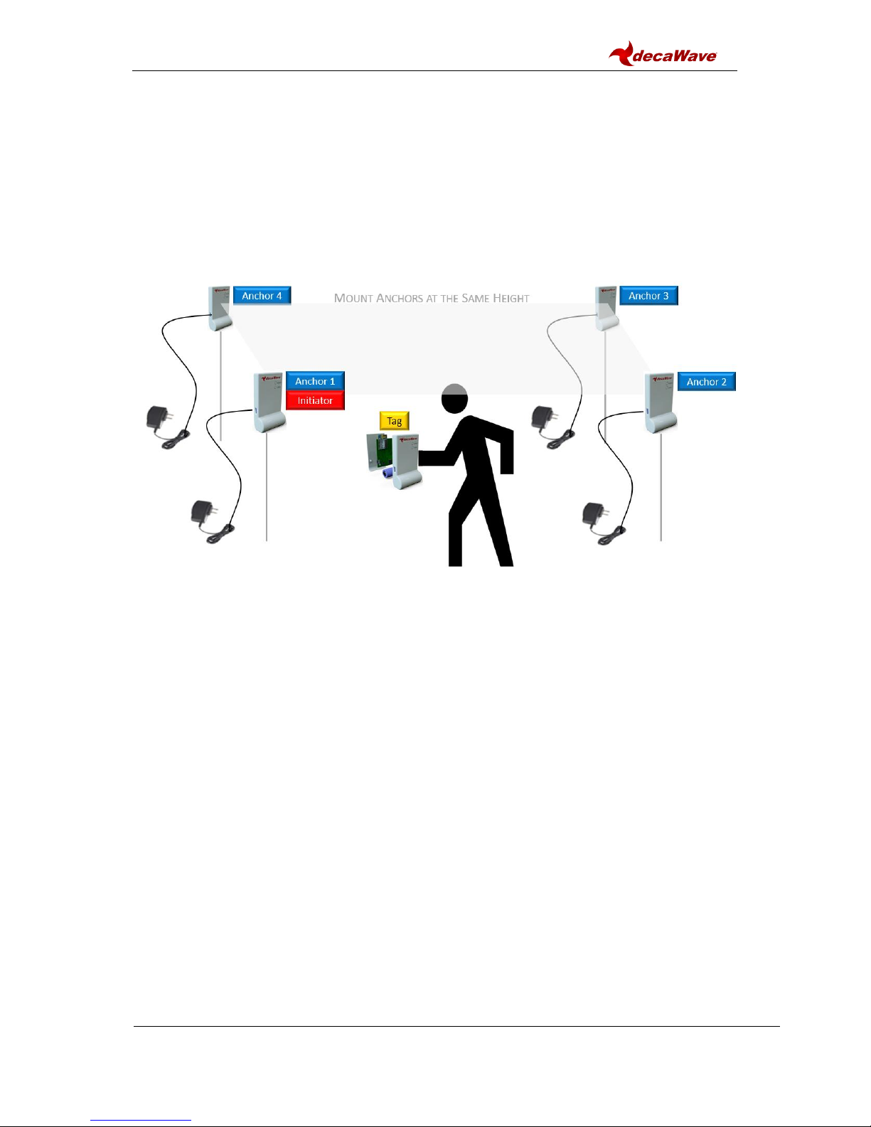
5 SYSTEM SETUP &PREPARATION
5.1 Prepare the Anchors
Select some of the RTLS units as anchors –3 is the minimum for RTLS but at least 4
is recommended for accuracy
Mount the anchors on the wall or on tripods (as shown in the figure below)
oMounting them high will give better performance (due to Line-of-Sight)
Power the anchors using USB batteries or USB power supplies
Figure 3: Positioning of Anchors and Tags
5.2 Prepare the Tags
Select the remaining RTLS units as tags - at least 1 is required
Battery Power
oOpen the plastic enclosure of each unit
oInsert the rechargeable battery (purchased separately)
oClose the plastic enclosure
USB Power Supply
oPower the tags using USB power supply or USB battery
5.3 Prepare the Android Tablet
Download the latest Android .apk file for the “RTLS System Manager” application
from the Decawave website
Install the file on your Android device by tapping the APK file in the Downloads
section

MDEK1001 Kit User Manual
© Decawave 2017
OP-MDEK1001-System-User-Manual-1.0
Page 15
6 SYSTEM CONFIGURATION EXAMPLES
6.1 1 Anchor + 1 Tag
This configuration can be used for a simple proximity demonstration:
Configure 1 RTLS unit as an initiator anchor by using the tablet (section 7) or PC
(section 8)
Configure 1 RTLS unit as a tag by using the tablet (section 7) or PC (section 8)
The PC can capture the ranges between the 2 devices into a log-file using a terminal
Figure 4: System Configuration Option: 1 Anchor, 1 Tag
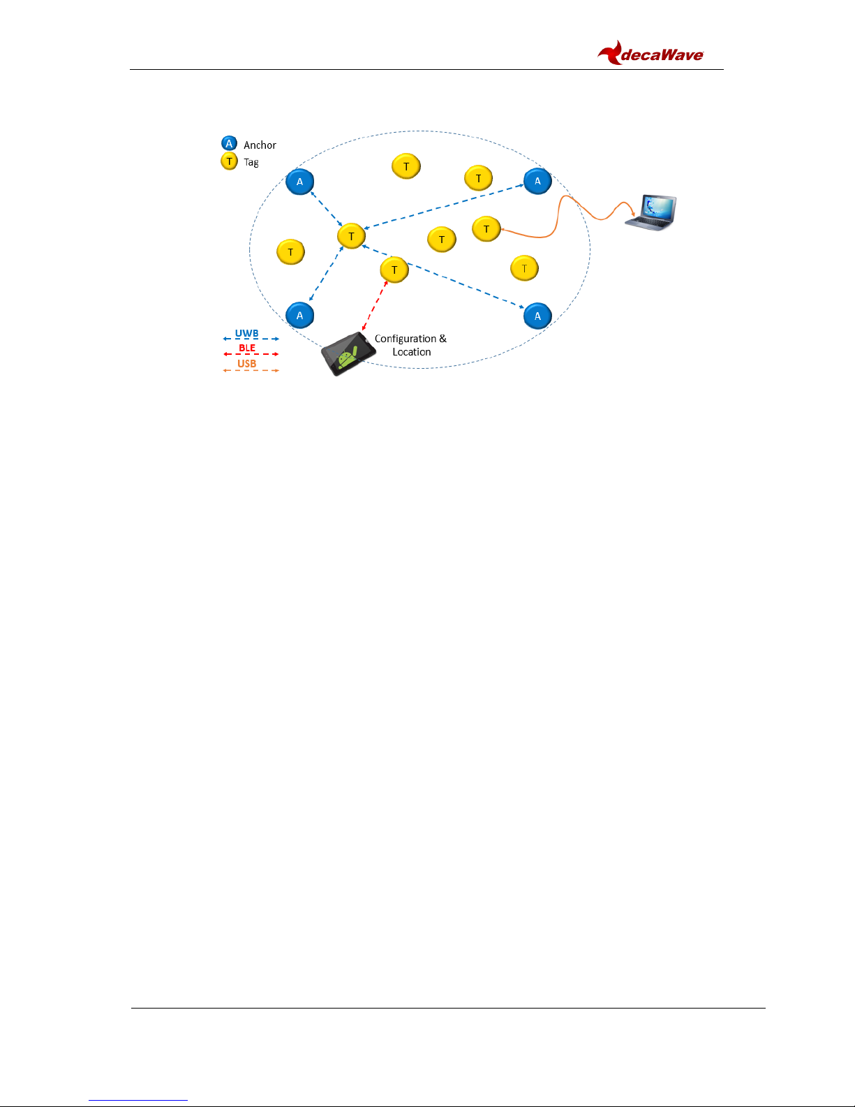
6.2 Configure 4 Anchors + 8 Tags
This configuration is the minimum recommended anchor configuration for an RTLS system:
Configure 4 RTLS units as anchors
Configure 8 RTLS units as tags
The tablet shows the tablet positions of up to 2 tags
Figure 5: System Configuration Option: 4 Anchors, 8 Tags
The number of open Bluetooth connections to the tablet will be limited to 3
All RTLS units in this demonstration system must be in Bluetooth range of the tablet
A tag can also be connected to a PC as shown in Figure 6
MDEK1001 Kit User Manual
© Decawave 2017
OP-MDEK1001-System-User-Manual-1.0
Page 16
Figure 6: System Configuration Option: 4 Anchors, 8 Tags & PC logging

MDEK1001 Kit User Manual
© Decawave 2017
OP-MDEK1001-System-User-Manual-1.0
Page 17
6.3 11 Anchors + 1 Tag
This configuration uses as many anchors as possible (in this kit) to show how the anchors
scale and a tag can dynamically select the best anchors, as it traverses though the area
covered by the anchors.
Configure 11 RTLS units as anchors
Configure 1 RTLS unit as a tag
The tag that is being tracked on the tablet must be in Bluetooth range of the tablet.
Figure 7: System Configuration Option: 11 Anchors, 1 Tag
MDEK1001 Kit User Manual
© Decawave 2017
OP-MDEK1001-System-User-Manual-1.0
Page 18
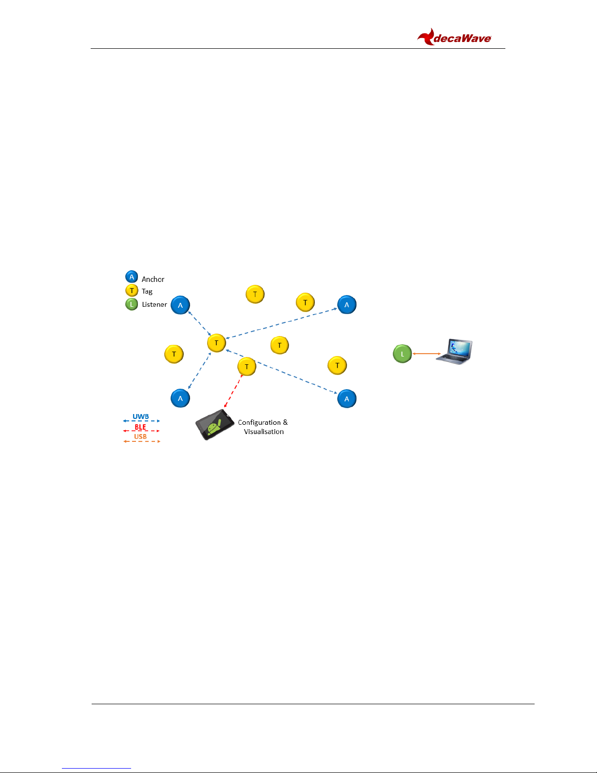
6.4 4 Anchors + 7 Tags + 1 Listener
By configuring one of the devices as a listener device, the data can be captured to a PC
directly.
Set one of the RTLS units (tag or anchor) into PASSIVE mode. In this mode the
UWB is enabled but it is not participating in the network
Connect a PC to this RTLS unit via a USB cable
On the PC open a shell terminal
To report the position of all tags that the listener can hear
oType the command “les”(location-engine-show: ASCII format)
or type: “lec”(location-engine-show: csv format) –
oSave data from terminal to log file
In this mode, only position is printed (not individual ranges)
The tag that is being tracked on the tablet must be in Bluetooth range of the tablet.
Figure 8: System Configuration Option: 4 Anchors, 7 Tags, 1 Listener
MDEK1001 Kit User Manual
© Decawave 2017
OP-MDEK1001-System-User-Manual-1.0
Page 19
7 USAGE GUIDE
Follow the steps below to get the DWM1001 Two-Way-Ranging Real Time Location System
(DRTLS) up-and-running.
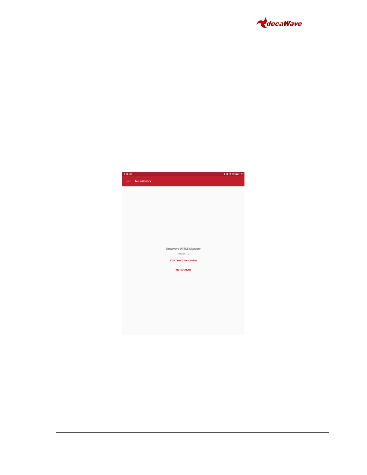
7.1 Open the Android Application
Open the Decawave DRTLS Manager
If no networks have been previously saved the application will open on the home
screen
If a network was previously saved the application will open on the last viewed
network screen
The home screen will show:
o“Decawave DRTLS Manager”
oApplication version
oButton to “Start Device Discovery”
oButton to go to the “Instructions” page
Figure 9: Decawave DRTLS Manager Home Screen

MDEK1001 Kit User Manual
© Decawave 2017
OP-MDEK1001-System-User-Manual-1.0
Page 20
7.2 Start Device Discovery
Tap “Start Device Discovery”
The application will automatically discover all devices that are in range and powered
on
Figure 10: Device Discovery Screen
Devices will be grouped into
o‘NETWORKS’
o‘UNASSIGNED DEVICES’
o‘UNASSIGNED NETWORKS’
The following information is shown under each device:
oDevice Type (Anchor or Tag)
oDevice Name in the form DW1234
oNetwork
oBluetooth address
oDevice ID
The user can select a specific device by tapping an individual device
oThe user will get the option to create a New Network name
Alternatively, to select multiple devices:
oTap-and-hold a single device
oThe checkmark symbol will be shown on the left of that device
oOther devices can be tapped and added to the selection
oOnce selected, the button “ASSIGN” in the upper right-hand corner can be
tapped to add these devices to a new (or existing) network
Other manuals for MDEK1001
2
Table of contents
Other decaWave Motherboard manuals


