Siemens Nixdorf D818 User manual

PC
System board with PCI Bus
PCD-5H
The Intel Inside Logo is
a registered trademark
Technical Manual of Intel Corporation

PC
Published by
Siemens Nixdorf Informationssysteme AG
33094 Paderborn
81730 München
Order No.: A26361-D818-Z120-1-7619
Printed in the Federal Republic of Germany
AG 1293 12/93
A26361-D818-Z120-1-7619

Is there ...
... any technical problem or other ... anything you want to tell us
question you need clarified? about this manual?
Please send us your comments quoting
Please contact: the order number of the manual.
– one of our IT Service Shops
– your sales partner Siemens Nixdorf Informationssysteme AG
– your sales office User Documentation Department
BS2000 QM2, Otto-Hahn-Ring 6,
You will find the addresses of the 81730 München, Germany
IT Service Shops in the enclosed
warranty coupon booklet. Fax: (0 89) 6 36-4 04 43
This manual was produced using paper treated with chlorine-free bleach.
Introduction
Important notes
System board Settings and
add-on modules
with PCI Bus
Interface assignment
Error messages
Technical Manual Index
December 1993 edition

Would you like to know more ...
... about this product
... or about another aspect of information technology?
Our Training Centers will be glad to help.
Siemens Nixdorf has Training Centers at strategic
locations in Germany and more than 20 countries worldwide.
Please write to:
Siemens Nixdorf
Area Training Management Europe North
125-135 Staines Road, Hounslow, Middlesex, TW3 3JB
United Kingdom
or call
Ron Johnson, Hounslow
Tel.: .44 344 850 990
Fax.: .44 344 850 991
Adaptec is a registered trademark of Adaptec Inc
Pentium is a registered trademark of Intel Corporation, USA.
Microsoft, MS and MS-DOS are registered trademarks and Windows is a trademark of
Microsoft Corporation.
PS/2 is a registered trademark of International Business Machines, Inc.
UNIX is a registered trademark of UNIX System Laboratories.
Copyright Siemens Nixdorf Informationssysteme AG 1993
The reproduction, transmission or use of this document or its contents is not permitted without
express written authority.
Offenders will be liable for damages
All rights, including rights created by patent grant or registration of a utility model or design,
are reserved.
Delivery subject to availability. Right of technical modification reserved.

Contents
Introduction 1
Explanation of symbols 1
Features 2
Important notes 5
Notes on software 6
Settings and add-on modules 7
Settings in the setup menu 7
Settings using the STANDARD CMOS SETUP option 9
Settings using the ADVANCED CMOS SETUP option 11
Settings using the PERIPHERAL MANAGEMENT SETUP option 18
Settings using jumpers 21
Jumper J7A1 21
Recovering BIOS 22
BIOS update 22
Deleting CMOS RAM 22
Video mode 23
Invoking setup menu 23
Main memory 24
Installing a memory module 25
Removing a memory module 25
Interface assignment 27
Connector J11H1 for power supply 27
Connector J3A1 for fan 27
Connector J1F1 for external loudspeaker 28
Connector J1G1 for indicator hard disk drive 28
Connector J1F3 for indicator system unit on 28
VESA feature connector J10A1 29
Error messages 31
Beep codes 31
Error messages 32
Index 37
A26361-D818-Z120-1-7619

Introduction
This description applies for the system board with PCI Bus (Peripheral Component
Interconnect) and the Pentium 60 MHz processor.
Explanation of symbols
The meanings of the symbols and fonts used in this manual are as follows:
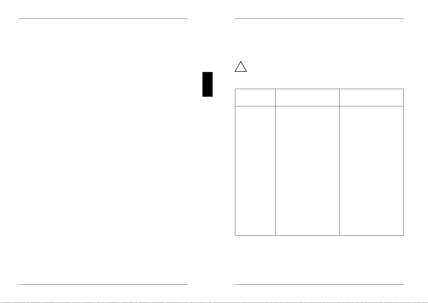
!Pay particular attention to texts marked with this symbol. Failure to observe
this warning endangers your life, destroys the system, or may lead to loss of
data.
This symbol is followed by supplementary information, remarks and tips.
i
Texts which follow this symbol describe activities that must be performed in the
order shown.
This symbol means that you must enter a blank space at this point.
↵ This symbol means that you must press the Enter key.
Texts in this typeface are screen outputs from the PC.
Texts in this bold typeface are the entries you make via the keyboard.
Texts in italics indicate commands or menu items.
"Quotation marks" indicate highlighted text and names of chapters.
A26361-D818-Z120-1-7619 1
Introduction
Features
– 64-bit microprocessor Pentium 60MHz with integrated math coprocessor and
2*8 Kbyte internal cache memory (first level cache; 8 Kbyte data cache, 8 Kbyte
address cache)
– Second level cache memory on the system board: 256 Kbyte
– Memory configuration on system board: 8 Mbyte to 128 Mbyte RAM onboard
– Video memory on the system board: 1 Mbyte
– Flash EPROM
– Real-time clock chip with battery and 128 Byte Setup memory in CMOS RAM
– Loudspeaker
– Floppy disk drive controller (up to 2.88 Mbyte format)
– Hard disk controller for IDE hard disk drives
– VGA controller
– Bus interface for platter with 4 ISA slots and 2 PCI slots
– Connector for IDE hard disk drive
– Connector for floppy disk drive
– Connector for external loudspeaker
– VESA feature connector
– Parallel interface
– Two serial interfaces
– PS/2 mouse interface
– PS/2 keyboard port
– Monitor interface
2A26361-D818-Z120-1-7619

Introduction
12345678910 11 12
13
14
15
16
17
18
19
20
21
1 = Monitor interface 12 = Sockets J4H1 and J4H2
2 = Parallel interface for main memory (Bank 0)
3 = Serial interface (Ser 2) 13 = Connector J1G1 for indicator
4 = Serial interface (Ser 1) hard disk drive
5 = PS/2 mouse interface (bus mouse) 14 = Connector J1F3 for indicator
6 = PS/2 keyboard port system unit on
7 = Connector J11H1 for power supply 15 = Connector J1F1 for external
8 = Real-time clock chip with lithium battery loudspeaker
9 = Connector J8J2 for standard 16 = Processor with heat sink
IDE hard disk drive 17 = Connector J3A1 for fan
10 = Connector J8J1 for floppy disk drive 18 = Bus interface
11 = Sockets J4F1 and J4G1 19 = Video memory
for main memory (Bank 1) 20 = VESA feature connector J10A1
21 = Sockets for additional video memory
A26361-D818-Z120-1-7619 3
Introduction
Possible screen resolution
The screen resolutions in the following table refer to the VGA controller on the
system board.
If you are using an external CRT controller, you will find the possible screen
resolution in the Operating Manual of the CRT controller.
Screen Refresh Horizontal- Max. number
resolution rate (Hz) rate (kHz) of colours
640x480 60 31,5 256
640x480 60 31,5 65536
640x480 60 31,5 16777216
640x480 72 37,7 256
640x480 72 37,7 65536
800x600 56 35,3 256
800x600 56 35,3 65536
800x600 60 37,8 256
800x600 60 37,8 65536
800x600 70 44,4 256
800x600 72 48,2 256
800x600 75 49,6 256
800x600 47,5 (interl.) 34 256
800x600 47,5 (interl.) 34 65536
1024x768 60 48,5 256
1024x768 66 54,5 256
1024x768 70 56,7 256
1024x768 72 58,5 256
1024x768 75 60,2 256
1024x768 43,5 (interl.) 35,4 256
1280x1024 43,5 (interl.) 49,9 16
*) 1280x1024 43,5 (interl.) 49,9 256
1280x1024 47,5 (interl.) 50,4 16
*) 1280x1024 47,5 (interl.) 50,4 256
*) Only with 2 Mbyte of video memory
The screen resolution depends on the connected monitor. How to set the screen
resolution is described in the Operating Manual of the PC.
4A26361-D818-Z120-1-7619

Important notes
!Please note the information provided in the chapter "Safety" in the
Operating Manual of the PC.
The real-time clock chip on the system board includes a lithium battery
which may be replaced only by authorized personnel. Incorrect handling
may lead to a risk of explosion.
The chip may be replaced only with an identical chip or with a type
recommended by the manufacturer.
The chip must be disposed of in accordance with local regulations
concerning special waste.
Be sure to read this page carefully and note the information before you
open the PC.
Modules with electrostatic sensitive devices (ESD) may be identified by labels.
When you handle modules fitted with ESDs, you must observe the following points
under all circumstances:
– When you handle modules fitted with ESDs, you must always discharge yourself
(e.g. by touching a grounded object) before working.
– The equipment and tools you use must be free of static charges.
– Pull out the power plug before inserting or pulling out modules containing ESDs.
– Always hold modules with ESDs by their edges.
– Never touch pins or conductors on modules fitted with ESDs.
A26361-D818-Z120-1-7619 5
Important notes
Notes on software
Program with time loops
Problems can occur with programs in which time loops have been implemented
through software loops. This applies in particular to older programs which were
written for 8 MHz processors.
SCO-UNIX on devices with Pentium processor
If you use the Pentium processor, the Adaptec-SCSI controller cannot be
addressed under SCO-UNIX 3.2.4 and ODT 2.0.
To solve this problem, you can order from SCO a set of SLS (Support Level
Supplement) floppies (consisting of 3 floppy disks) under the number uod361,
free of charge, or contact SNI's spare parts service.
The problem no longer exists in the new releases of SCO-UNIX 3.2.4.2 and
ODT 2.1.
There will be no support for older versions (SCO-UNIX versions lower than 3.2.4
and ODT versions lower than 2.0).
6A26361-D818-Z120-1-7619
Settings and add-on modules
You can make settings in the setup menu or using the jumpers on the system
board.
Settings in the setup menu
The setup menu displays settings and technical information on the PC
configuration. The Operating Manual describes how to invoke the setup menu and
change menu entries. Pressing the function key F1 provides help information on
each entry field.
AMIBIOS SETUP PROGRAM - BIOS SETUP UTILITIES
(C)1992 American Megatrends Inc., All Rights Reserved
ADVANCED CMOS SETUP
PERIPHERAL MANAGEMENT SETUP
CONFIGURE WITH BIOS DEFAULTS
CONFIGURE WITH POWER-ON DEFAULTS
CHANGE PASSWORD
WRITE TO CMOS AND EXIT
DO NOT WRITE TO CMOS AND EXIT
Standard CMOS Setup for Changing Time, Date, Hard Disk Type, etc.
ESC:Exit
↓→↑←
: Sel
F2
/
F3
:Color
F10
:Save & Exit
STANDARD CMOS SETUP
Example of a first screen page of the setup menu
A26361-D818-Z120-1-7619 7
Settings and add-on modules
The setup menu provides eight items. The first three offer a variety of setting
options that are described below.
STANDARD CMOS SETUP
This option enables you to make the following basic settings:
– Date and time on your PC
– Floppy disk drives
– Hard disk drives
– Keyboard
ADVANCED CMOS SETUP
This option enables you to set the following functions:
– Key repeat function
– Message "Press <F1> Key if you want to run Setup"
– Num Lock function
– Loading the operating system
– Cache memory
– Prompting for network password
– ISA Linear Frame Buffer
– Shadowing function
– Base memory
– IDE-DMA transfer
– IDE Multiple Sector Mode
– ISA bus timing
– Interrupts IRQ9, IRQ10 and IRQ11
PERIPHERAL MANAGEMENT SETUP
This option enables you to set the following peripherals:
– Floppy disk drive controller
– Hard disk drive controller
– Addresses of the serial ports
– Addresses of the parallel ports
– Interrupt status
– Parallel port mode
CONFIGURE WITH BIOS DEFAULTS
This option enables you to set all settings of the setup menu to default values
(ROM).
8A26361-D818-Z120-1-7619

Settings and add-on modules
CONFIGURE WITH POWER-ON DEFAULTS
This option enables you to set all settings of the setup menu to default values, by
means of which it is always possible to start the PC.
CHANGE PASSWORD
This option enables you to assign, change or delete a password (see Operating
Manual of the PC).
WRITE TO CMOS AND EXIT
This option saves the settings you have made to CMOS RAM and exits the setup
menu.
DO NOT WRITE TO CMOS AND EXIT
This option exits the setup menu without saving the settings you have made.
Settings using the STANDARD CMOS SETUP option
Date
Time The field for Date contains the current date, and the field for Time contains
the current time of the PC. If you change the date or time, you must use the
formats mm/dd/yy (month/day/year) and hh/mm/ss (hours/minutes/seconds)
respectively.
!If the fields for Date and Time show the wrong values after switching
the PC off and back on, then the battery is empty. Please contact the
service department.
Floppy Drive A:
Floppy Drive B:
Both fields show the type of floppy disk drives installed.
Possible entries: 360K, 1.2M, 720K, 1.44M, 2.88M and NOT INSTALLED.
Default entry for Floppy Drive A:1.44M
Default entry for Floppy Drive B:NOT INSTALLED
A26361-D818-Z120-1-7619 9
Settings and add-on modules
Drive C: Type
Drive D: Type
Drive E: Type
Drive F: Type
These fields show the type of hard disk drives installed. The values for
Drive C: Type are valid for the default hard disk drive.
Possible entries:
AUTO-CONFIG
The BIOS checks the installed hard disk drive and, in the case of IDE hard
disk drives, automatically configures the values for Cyln, Head, Sect and
Size.
USER TYPE 1
You are responsible for entering the values for Cyln, Head, Sect and Size
yourself if the BIOS does not recognize the installed hard disk drive (e.g.
SCSI or ESDI hard disk drives).
USER TYPE 2
Same as USER TYPE 1.
It is not possible to load the operating system if the wrong hard disk
itype is entered. In this case an MS-DOS message indicating that the
operating system is missing is displayed.
Default entry for C: USER TYPE 1
Default entry for D: to F: AUTO-CONFIG
Drive C: Timeout
Drive D: Timeout
Drive E: Timeout
Drive F: Timeout
In this field you specify the time allowed for the BIOS to detect the installed
hard disk drive for automatic configuration. An error message is displayed if
the BIOS exceeds this time. The values for Drive C: Timeout are valid for the
default hard disk drive.
Possible entries: 0, 5, 15, 31 seconds
Default entry: 5 seconds
10 A26361-D818-Z120-1-7619

Settings and add-on modules
Keyboard
In this field you indicate whether you have attached a keyboard.
Possible entries:
Installed
A keyboard is attached.
Not Installed
No keyboard is attached.
Default entry: Installed
Base Memory
This field indicates the size of the available base memory below 1 Mbyte.
Extended Memory
This field indicates the size of the memory above 1 Mbyte.
Settings using the ADVANCED CMOS SETUP option
Typematic Rate Programming
This field allows you to enable or disable the Typematic Rate Delay and
Typematic Rate fields.
Possible entries:
Enabled
You can make settings in the fields Typematic Rate Delay and
Typematic Rate.
Disabled
You cannot make settings in the fields Typematic Rate Delay and
Typematic Rate.
Default entry: Disabled
A26361-D818-Z120-1-7619 11
Settings and add-on modules
Typematic Rate Delay
The Typematic Rate Programming field must indicate Enabled.
In this field you can specify the time, in milliseconds, after which the key
repeat function takes effect. Key repeat means that a key is repeated for as
long as the key is held down.
Possible entries: 250, 500, 750 or 1000 (milliseconds)
Default entry: 500
Typematic Rate
The Typematic Rate Programming field must indicate Enabled.
In this field you can specify how often the key character is repeated in a
second if the key is held down.
Possible entries: 30, 24, 20, 15, 12, 10, 8 or 6(characters/second)
Default entry: 15
Press <F1> Message Display
This field enables you to specify whether your PC is to display the message
Press <F1> Key if you want to run Setup when the system is
booted.
Possible entries:
Enabled
The message Press <F1> Key if you want to run Setup is
displayed.
Disabled
The message Press <F1> Key if you want to run Setup is
not displayed.
Default entry: Enabled
12 A26361-D818-Z120-1-7619

Settings and add-on modules
System Boot UP Num Lock
This field enables you to specify whether the lowercase level or uppercase
level of the numeric keypad is active when the system is booted.
Possible entries:
OnThe uppercase level, i.e. the digit and comma keys, is active.
OffThe lowercase level is active, i.e. on the numeric keypad the lower
characters of double-labeled keys are valid.
Default entry: On
System Boot UP Sequence
This field enables you to specify from which drive the operating system is to
be booted.
Possible entries:
A:, C:
When the system is booted, the BIOS attempts to start the operating
system from drive A:. If it does not find the operating system there, it loads
the operating system from drive C:.
C:, A:
When the system is booted, the BIOS attempts to start the operating
system from drive C:. If it does not find the operating system there, it
loads the operating system from drive A:.
C: When the system is booted, the BIOS starts the operating system from
drive C:. It is not possible to load the operating system from drive A:.
Default entry: A:, C:
System Boot UP CPU Speed
This field enables you to set the CPU speed.
Possible entries: High (60 MHz) or Low (8 MHz)
Default entry: High
A26361-D818-Z120-1-7619 13
Settings and add-on modules
Cache Memory
In this field you can specify whether a part of the main memory is mapped to
the very fast cache memory (SRAM). This results in faster program execution
and faster data access operations.
Possible entries:
Enabled
The function is enabled.
The first-level cache memory (in the CPU) and the second-level cache
memory (on the system board) are used.
Disabled
The function is disabled.
Neither the first-level cache memory nor the second-level cache memory
can be used.
You must disable the function if the access time for application
iprograms is too short.
Default entry: Enabled
Network Password Checking
This field applies only if you have assigned a password.
You use it to set the effect of a password.
Possible entries:
Disabled
You are prompted to enter a password before the operating system is
started. The operating system is started once you have entered the
correct password.
Enabled
The keyboard is locked after the operating system is started. The
keyboard is released once you have entered the correct password.
Default entry: Disabled
14 A26361-D818-Z120-1-7619

Settings and add-on modules
ISA Linear Frame Buffer
This field enables you to make available a linear frame buffer for an external
ISA graphics controller. Performance is enhanced if the external ISA
graphics controller can use a linear frame buffer.
Possible entries: 1MB, 2MB, 4MB or Disabled
Default entry: Disabled
Set Linear Frame Buffer to
This field shows the address of the linear frame buffer if the field ISA Linear
Frame Buffer contains a value.
If the field ISA Linear Frame Buffer contains the entry Disabled, this field
contains N/A (not applicable).
Disable Shadow Memory Size
If your PC contains an ISA expansion board, it may be necessary that a
memory area is not copied to shadow RAM. The size and location of this
memory area depends on the ISA expansion board.
This field enables you to specify the size of the memory area (max. 64
Kbytes) not to be copied into fast shadow RAM. The area must lie within the
addresses C0000H and DFFFFH.
Possible entries:
Disabled
The entire memory area (C0000H to DFFFFH) is copied into fast shadow
RAM.
16KB, 32KB, 48KB or 64KB
This entry specifies the size of the memory area that is not to be copied
into fast shadow RAM.
You must specify the location of the memory area (base address) in the
field Disable Shadow Memory Base.
Default entry: Disabled
A26361-D818-Z120-1-7619 15
Settings and add-on modules
Disable Shadow Memory Base
This field is not applicable if the field Disable Shadow Memory Size contains the
entry Disabled.
This field enables you to specify the base address of the memory area that is
not to be copied into fast shadow RAM.
Possible entries: C0000H, C4000H, C8000H, CC000H, D0000H, D4000H,
D8000H or DC000H
Default entry: C0000H
Base Memory Size
This field enables you to set the size of the base memory (below 1 Mbyte).
Possible entries: 640 KB or 512 KB
Default entry: 640 KB
IDE DMA Transfer Mode
This entry enables you to set the IDE-DMA transfer mode for your IDE hard
disk drive.
The IDE-DMA transfer mode actually used depends on the installed IDE hard
disk drive.
Possible entries:
Standard
Compatible with DMA transfer mode.
Type B
ISA-DMA transfer mode.
Type F
The fastest IDE-DMA transfer mode. The optimum values are used for the
installed IDE hard disk drive.
Disabled
The function is disabled.
Default entry: Type F
16 A26361-D818-Z120-1-7619

Settings and add-on modules
IDE Multiple Sector Mode
This field enables you to specify how many sectors are transferred during
each hard disk access.
The actual number of transferred sectors per access depends on the
installed IDE hard disk drive. The entry 64 S/B automatically sets the optimum
values for the installed IDE hard disk drive.
Possible entries: 1, 2, 4, 8, 16, 32 or 64 S/B (sectors/access operation)
Default entry: 64 S/B
Enhanced ISA Timing
This field enables you to set the timing of the ISA bus.
Possible entries:
Enabled
The timing of the ISA bus is 10 MHz.
Disabled
The timing of the ISA bus is 8 MHz.
Default entry: Disabled
ISA IRQ9
ISA IRQ10
ISA IRQ11
You must enter Used in the Interrupt field if one of the three interrupts is used
by an installed ISA board.
Possible entries:
Used
The interrupt is used by an ISA board.
Free
The interrupt is available for automatic PCI configuration.
Default entry: Free
A26361-D818-Z120-1-7619 17
Settings and add-on modules
Settings using the PERIPHERAL MANAGEMENT SETUP option
Programming Option
This field enables you to specify whether the peripherals (controlled by the
I/O controller) are configured automatically or manually.
Possible entries:
Auto
Peripheral devices are detected and configured automatically. The fields
that follow are not applicable.
Manual
The peripheral devices must be set manually using the fields that follow.
Default entry: Auto
On-Board Floppy Drive
Any entry in this field is not applicable if the Programming Option field contains
the entry Auto.
This field allows you to enable or disable the floppy drive controller on the
system board.
Possible entries:
Enabled
The floppy drive controller is enabled.
Disabled
The floppy drive controller is disabled.
Default entry: Enabled
18 A26361-D818-Z120-1-7619

Settings and add-on modules
On-Board IDE Drive
Any entry in this field is not applicable if the Programming Option field contains
the entry Auto.
This field allows you to enable or disable the hard disk drive controller on the
system board.
Possible entries:
Enabled
The hard disk drive controller is enabled.
Disabled
The hard disk drive controller is disabled.
Default entry: Enabled
First Serial Port Address
Second Serial Port Address
Any entry in this field is not applicable if the Programming Option field contains
the entry Auto.
This field enables you to set the first and second serial port.
Possible entries:
3F8H
The serial port is set to the address 3F8H and to IRQ4.
3E8H
The serial port is set to the address 3E8h and to IRQ4.
2F8H
The serial port is set to the address 2F8H and to IRQ3.
2E8H
The serial port is set to the address 2E8H and to IRQ3.
DISABLED
The serial port is disabled.
Default entry: 3F8H
A26361-D818-Z120-1-7619 19
Settings and add-on modules
Parallel Port Address
Any entry in this field is not applicable if the Programming Option field contains
the entry Auto.
This field enables you to set the parallel port.
Possible entries:
378H
The parallel port is set to the address 378H and to IRQ7.
278H
The parallel port is set to the address 278H and to IRQ5.
3BCH
The parallel port is set to the address 3BCH and to IRQ7.
DISABLED
The parallel port is disabled.
Default entry: 378H
IRQ active State
This field enables you to specify whether the interrupt signals are high or low.
Possible entries: High or Low
Default entry: High
Parallel Port Mode
Any entry in this field is not applicable if the Programming Option field contains
the entry Auto.
This field enables you to set the transfer mode for the parallel port. The
parallel port supports extended transfer in accordance with EPP and fast
transfer in accordance with EPP.
Possible entries:
Normal
The parallel port can send only.
Extended
The parallel port can send and receive.
Default entry: Normal
20 A26361-D818-Z120-1-7619

Settings and add-on modules
Settings using jumpers
FG
1
2
3
BC
1
2
3
DE
1
2
3
J12H1
J13H1
J13H3
J7A1
A
1
2
3
J7A1 = may not be changed J13H3 = jumper for Video mode
J12H1 = jumper for Flash BIOS and setup menu
J13H1 = jumper for CMOS RAM
Jumper J7A1
The setting of jumper J7A1 may not be changed.
A26361-D818-Z120-1-7619 21
Settings and add-on modules
Recovering BIOS
Using jumper J12H1-B you can recover the BIOS after an errored BIOS update. To
do so, you need a recovery diskette (please contact the service department).
If you enable recovery, BIOS starts from drive A: and restores the BIOS in the
EEPROM.
BIOS recovery = Jumper J12H1-B set to 1-2
Normal operation = Jumper J12H1-B set to 2-3
Default setting:
Jumper J12H1-B set to 2-3 = Normal operation
BIOS update
Using jumper J12H1-C you can enable or disable BIOS updating.
If you enable updating, the BIOS in EEPROM can be overwritten.
BIOS update not possible = Jumper J12H1-C set to 1-2
BIOS update possible = Jumper J12H1-C set to 2-3
Default setting:
Jumper J12H1-C set to 1-2 = BIOS update not possible
Deleting CMOS RAM
Using jumper J13H1-D you can delete the CMOS RAM. If you delete CMOS RAM,
the setup menu contains default entries.
Normal operation = Jumper J13H1-D set to 1-2
Delete CMOS RAM = Jumper J13H1-D set to 2-3
Default setting:
Jumper J13H1-D set to 1-2 = Normal operation
22 A26361-D818-Z120-1-7619
Settings and add-on modules
Video mode
Using jumper J13H3-F you can set the video mode for the screen controller.
Monochrome display = Jumper J13H3-F set to 1-2
Color display = Jumper J13H3-F set to 2-3
Default setting:
Jumper J13H3-F set to 2-3 = Color display
Invoking setup menu
Using jumper J13H3-G you can enable or disable invocation of the setup menu.
Setup menu invocation is possible = Jumper J13H3-G set to 1-2
Setup menu invocation not possible = Jumper J13H3-G set to 2-3
Default setting:
Jumper J13H3-G set to 1-2 = Setup menu invocation is possible
A26361-D818-Z120-1-7619 23
Settings and add-on modules
Main memory
Four locations (J4H1 and J4H2 = Bank 0; J4F1 and J4G1 = Bank 1) are available
on the system board for connecting memory modules.
!You may only use quick memory modules (Access time = 70 nsec or less)!
Only the upgrade levels and slots listed in the table are permissible for the
memory configuration.
Memory memory modules in Bank 0 memory modules in Bank 1
configuration
8 Mbyte 2 of 4 Mbyte ----
10 Mbyte 2 of 1 Mbyte 2 of 4 Mbyte
12 Mbyte 2 of 2 Mbyte 2 of 4 Mbyte
16 Mbyte 2 of 4 Mbyte 2 of 4 Mbyte
16 Mbyte 2 of 8 Mbyte ----
18 Mbyte 2 of 1 Mbyte 2 of 8 Mbyte
20 Mbyte 2 of 2 Mbyte 2 of 8 Mbyte
24 Mbyte 2 of 4 Mbyte 2 of 8 Mbyte
32 Mbyte 2 of 8 Mbyte 2 of 8 Mbyte
32 Mbyte 2 of 16 Mbyte ----
34 Mbyte 2 of 1 Mbyte 2 of 16 Mbyte
36 Mbyte 2 of 2 Mbyte 2 of 16 Mbyte
40 Mbyte 2 of 4 Mbyte 2 of 16 Mbyte
48 Mbyte 2 of 8 Mbyte 2 of 16 Mbyte
64 Mbyte 2 of 16 Mbyte 2 of 16 Mbyte
64 Mbyte 2 of 32 Mbyte ----
66 Mbyte 2 of 1 Mbyte 2 of 32 Mbyte
68 Mbyte 2 of 2 Mbyte 2 of 32 Mbyte
72 Mbyte 2 of 4 Mbyte 2 of 32 Mbyte
80 Mbyte 2 of 8 Mbyte 2 of 32 Mbyte
96 Mbyte 2 of 16 Mbyte 2 of 32 Mbyte
128 Mbyte 2 of 32 Mbyte 2 of 32 Mbyte
X150 = Bank 0; X151 = Bank 1; X152 = Bank 2; X153 = Bank 3;
24 A26361-D818-Z120-1-7619
Settings and add-on modules
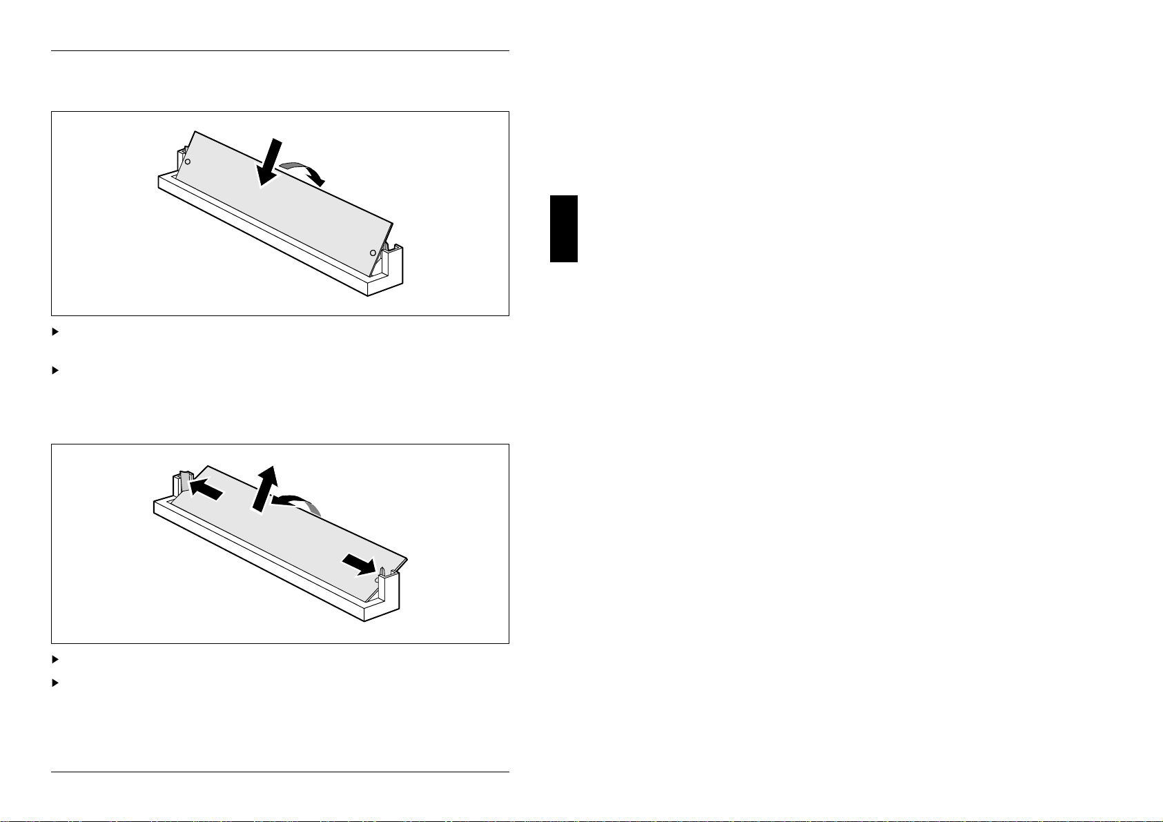
Installing a memory module
2
1
Insert the memory module at an angle into the appropriate slot (1).
Ensure that the two holes in the memory module line up with the holding pins.
Tilt the module back until it snaps into place (2).
Removing a memory module
2
1
1
3
Force the plastic holders carefully outward at left and right (1).
Tilt the module forward (2) and pull the module off upward (3).
A26361-D818-Z120-1-7619 25
Interface assignment
The assignment of the standard interfaces is described in the technical manual of
the PC (section "Technical data").
Connector J11H1 for power supply
1
12
Pin Meaning
1 Power Good
2 +5V
3 +12 V
4 -12 V
5 0 V
6 0 V
7 0 V
8 0 V
9 -5 V
10 +5 V
11 +5 V
12 +5 V
Connector J3A1 for fan
1
Pin Meaning
1 0 V
2 +12 V
3 0 V
4 0 V
5 +12 V
6 0 V
A26361-D818-Z120-1-7619 27
Interface assignment
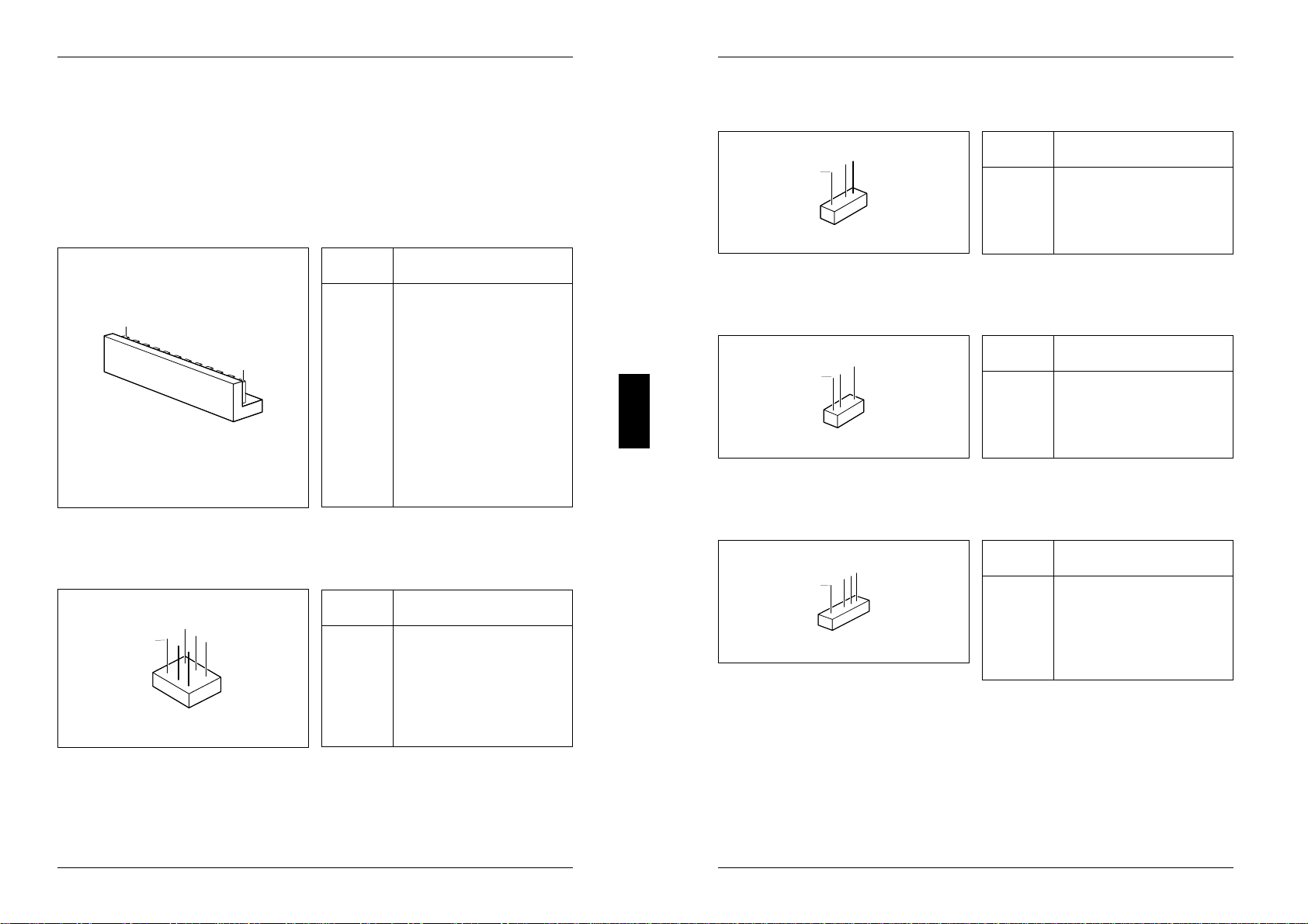
Connector J1F1 for external loudspeaker
1
Pin Meaning
1 data loudspeaker
2 coded
3 not used
4 +5 V
Connector J1G1 for indicator hard disk drive
1
Pin Signal name
1 +5 V
2 hard disk drive
3 coded
4 +5 V
Connector J1F3 for indicator system unit on
1
Pin Signal name
1 system unit on
2 coded
3 0 V
4 not used
5 0 V
28 A26361-D818-Z120-1-7619

Interface assignment
VESA feature connector J10A1
1
26
Pin Meaning Pin Meaning
1 0 V 14 Data 6
2 Data 0 15 0 V
3 0 V 16 Data 7
4 Data 1 17 0 V
5 0 V 18 Clock
6 Data 2 19 0 V
7 Select video 20 Blinking
8 Data 3 21 0 V
9 Select synchronization 22 Horizontal sync.
10 Data 4 23 not used
11 Select DAC 24 Vertical Sync.
12 Data 5 25 coded
13 not used 26 0 V
A26361-D818-Z120-1-7619 29
This manual suits for next models
1
Table of contents
Other Siemens Nixdorf Motherboard manuals

Siemens Nixdorf
Siemens Nixdorf D1111 User manual

Siemens Nixdorf
Siemens Nixdorf D756 User manual

Siemens Nixdorf
Siemens Nixdorf D1085 User manual

Siemens Nixdorf
Siemens Nixdorf D1042 User manual

Siemens Nixdorf
Siemens Nixdorf D969 User manual

Siemens Nixdorf
Siemens Nixdorf D802-C User manual

Siemens Nixdorf
Siemens Nixdorf D824 User manual

Siemens Nixdorf
Siemens Nixdorf D1025 User manual

Siemens Nixdorf
Siemens Nixdorf Fujitsu D1160 User manual

Siemens Nixdorf
Siemens Nixdorf D858 User manual


 manual ")


