Decoproyec CP19 Instructions for use

REF. 81 06 03 026 DECOPROYEC (rev0)
DECOPROYEC
C/Trilladores nº47 - Nave 4 y 5 (P.I. Los Molinos)
C.P.: 02520 –Chinchilla de Montearagón
(ALBACETE) –Spain
Tel. +34 967 261787 / +34 616897845
decoproyec@decoproyec.com
INSTRUCTION AND MAINTENANCE MANUAL
2
1. INFORMATIVE NOTE
This document has to be at disposal of the staff involved in the equipment use and
maintenance. If you have any questions or problems, please contact us.
In order to ensure that the equipment characteristics correspond to those specified in your
order, please, check it when you receive it and contact us in case any disagreement is
detected.
2. WASTE AND ENVIRONMENT
3. CHARACTERISTICS
TECHNICAL DATA
CP19
Nozzles
6 mm (5 & 8 mm as an option)
Body
Anodized external treatment
Air consumption
110 l./m. at 2.5 bar
125 l./m. at 3 bar
Funnel capacity:
5 Litros nylon
Weight
605 gr.
Air inlet
CR ¼
Supply system
Gravity
Functioning
Valve / continuous air
ATTENTION:
In order to ensure that the equipment characteristics correspond to those specified in
your order, please, check it when you receive it and contact us in case any
disagreement is detected.
REMEMBER:
To get rid of polluting and dangerous products, packaging, disused equipment
and tools and any type of waste produced by its activity in general, please use
the suitable waste sorting and treatment point for each case.
CP19
3
4. APPLICATIONS
Applicactions with projected cork, stippled-finish paints or “gotele”, textile
coatings on medium-sized surfaces.
5. OPERATING MODES
The gun can work in two different modes:
a) Valve mode
In this mode, the air outlet through the needle only happens whenever the trigger is
pulled. It is the default configuration, and the gun leaves the factory with it.
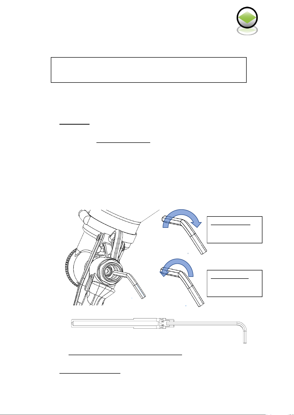
To change from the Continuous Air Mode to the Valve Mode, follow these steps:
1) Disassemble the product regulator (no.12 of the exploded view) and take the spring
out (no.13 of the exploded view).
2) Insert an Allen key size 4 at the back of the needle, whose cap has an Allen groove
(no.10 of the exploded view).
3) Turn the Allen key clockwise to tighten the cap.
b) Continuous air mode
Tighten the cap
Turn clockwise
Loosen the cap
Turn
counterclockwise

INSTRUCTION AND MAINTENANCE MANUAL
4
The air outlet through the needle is continuous in this mode regardless of when the
trigger is pulled.
To change from the Valve Mode to the Continuous Air Mode, follow these steps:
1) Disassemble the product regulator (no.12 of the exploded view) and take the spring
out (no.13 of the exploded view)
2) Insert an Allen key size 4 at the back of the needle, whose cap has an Allen groove
(no.10 of the exploded view).
3) Turn the Allen key counterclockwise to unlock the cap. Be careful when removing
the cap enough to open the continuous air holes but it can NEVER protrude the
needle.
6. WORKING INSTRUCTIONS
The size of the drop can be adjusted with the product regulator (no.12 of the exploded view);
turning clockwise you get bigger drops and counterclockwise smaller drops.
It is also important to know that the higher the product viscosity, the bigger the sprayed drops
will be.
Tighten the cap
Turn clockwise
Loosen the cap
Turn
counterclockwise

CP19
5
7. CLEANING PROCEDURE AND MAINTENANCE
First, empty the product tank. Fill it with water or the appropriate solvent, spray until it is
completely clean and dry the gun.
Finally, grease properly all the points where wear occurs more often such as the needle,
threads, trigger, and so on.
8. SAFETY DATA SHEET
Take in mind the following rules:
Do not use the spray gun in those operations for which it has not been designed.
Read all the warnings on the products you use.
Use approved masks.
Do not aim gun at people or animals.
Disconnect it from the compressed air network before any repair.
Use the gun in a well-ventilated area where there are no risks of explosion or fire.
Never exceed pressure of 8 bar.
Once the work is finished, close the product regulator completely (no.12 of the exploded
view) to prevent vaporization.
9. WARRANTY CERTIFICATE
1. It extends only and exclusively against any manufacturing defect.
2. The period of validity is 2 years from the date of purchase.
3. Warranty covers the repair in our facilities or our technical services.
4. The machine, whose fault is due to bumps, falls or similar facts, is excluded from any
warranty.
ATTENTION:
A misuse of the equipment can cause accidents, defects or malfunctioning.
Please, read carefully the following instructions.

INSTRUCTION AND MAINTENANCE MANUAL
6
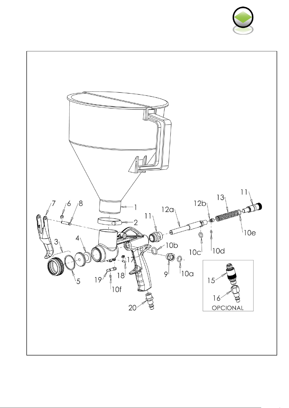
10. EXPLODED VIEW - CP 19
No.
Ref.
Description
1
50160B
Tank
2
50145B
Clamp
3
50566B
Nozzle nut and joint
4
502605B
Nozzle Ø 5 (as an option, not included as standard)
4
502606B
Boquilla Ø 6
4
502608B
Nozzle Ø 8 (as an option, not included as standard)
5
50267B1
Joint, 1unit
6
500061B
Seeger ring, 2 units
7
50150B
Trigger
8
50586B
Inox stud bolt
9
50152B
Packing nut
10
50609
Joints complete kit , (10a, 10b, 10c, 10d & 10e)
11
50154B
Bushing with regulator
12a
50607B
Needle
12b
50601B
Needle screw
13
50599B
Spring, 1 unit
15
50022B
Air regulator (as an option, not included as standard)
16
10CR1/4HB1
Female air inlet adaptor (as an option, not included as
standard)
17
50399
Seeger ring for the trigger limiter, 2 units
18
50606B
Stud bolt
19
50602B
Trigger limiter
20
10CR1/4MB1
Male air inlet adaptor
0308RX02
Complete kit
CP19
7
Exploded view Rev. 0

DECOPROYEC
C/Trilladores nº47 - Nave 4 y 5 (P.I. Los Molinos)
C.P.: 02520 –Chinchilla de Montearagón
(ALBACETE), Spain
Tel. +34 967 261787 / +34 616 897845
decoproyec@decoproyec.com
Table of contents
Popular Paint Sprayer manuals by other brands


Titan
Titan HELIX 0138010 operating manual

WAGNER
WAGNER PEA-C4 Twin-HiCoat operating manual

Task Force Tips
Task Force Tips G-Force INSTRUCTIONS FOR SAFE OPERATION AND MAINTENANCE

Boyens Backservice
Boyens Backservice Jelly instruction manual

Mesto
Mesto FERROX 3565 Instructions for use

Maruyama
Maruyama MS050 Owner's/operator's manual