Dedicated Mircros Dennard 2060 User manual
OPERATION MANUAL
HANDLEIDING
MANUEL D’INSTALLATION
MANUALE DI FUNZIONAMENTO
MANUAL DE FUNCIONAMIENTO

This product is marked with the CE symbol and indicates
compliance with all applicable directives.
Directive 89/336/EEC.
A “Declaration of Conformity” is held at Dedicated Micros Ltd.,
11 Oak Street, Swinton, Manchester, M27 4FL.

Dennard 2060 Operation Manual Page. 1
1. Introduction
Congratulations on choosing a Dennard 2060 Precision Dome camera.
Models covered in this guide include Dennard 2060, Dennard 2060 with drx, Dennard 2060
outdoor, Dennard 2060 outdoor with drx and Dennard 2060 fixed attitude.
This operation manual will provide all the necessary information to install the Dennard 2060
Precision Dome Camera. Please refer to the Menu System manual for operation and programming
features.
2. Index
1. Introduction. 1
2. Index. 1
3. List of contents. 2
4. Mounting configurations. 3
5. Safety bond. 4
6. Standard ceiling mounting. 5
7. Bracket mounting. 6
8. Tile mounting. 7
9. Dome mounting. 8
10. Electrical connections. 9
11. Address switches. 10
12. Control configurations. 11
13. Circuit diagrams. 12
14. Addendum contents. 13
addendum 1. Dennard 2060 fixed attitude dome camera. Addendum 1
addendum 2. Dennard 2060 fixed attitude connections. Addendum 2
addendum 3. Dennard 2060 fixed attitude ‘zoom cam’. Addendum 3
Dennard 2060 Operation Manual Page. 2
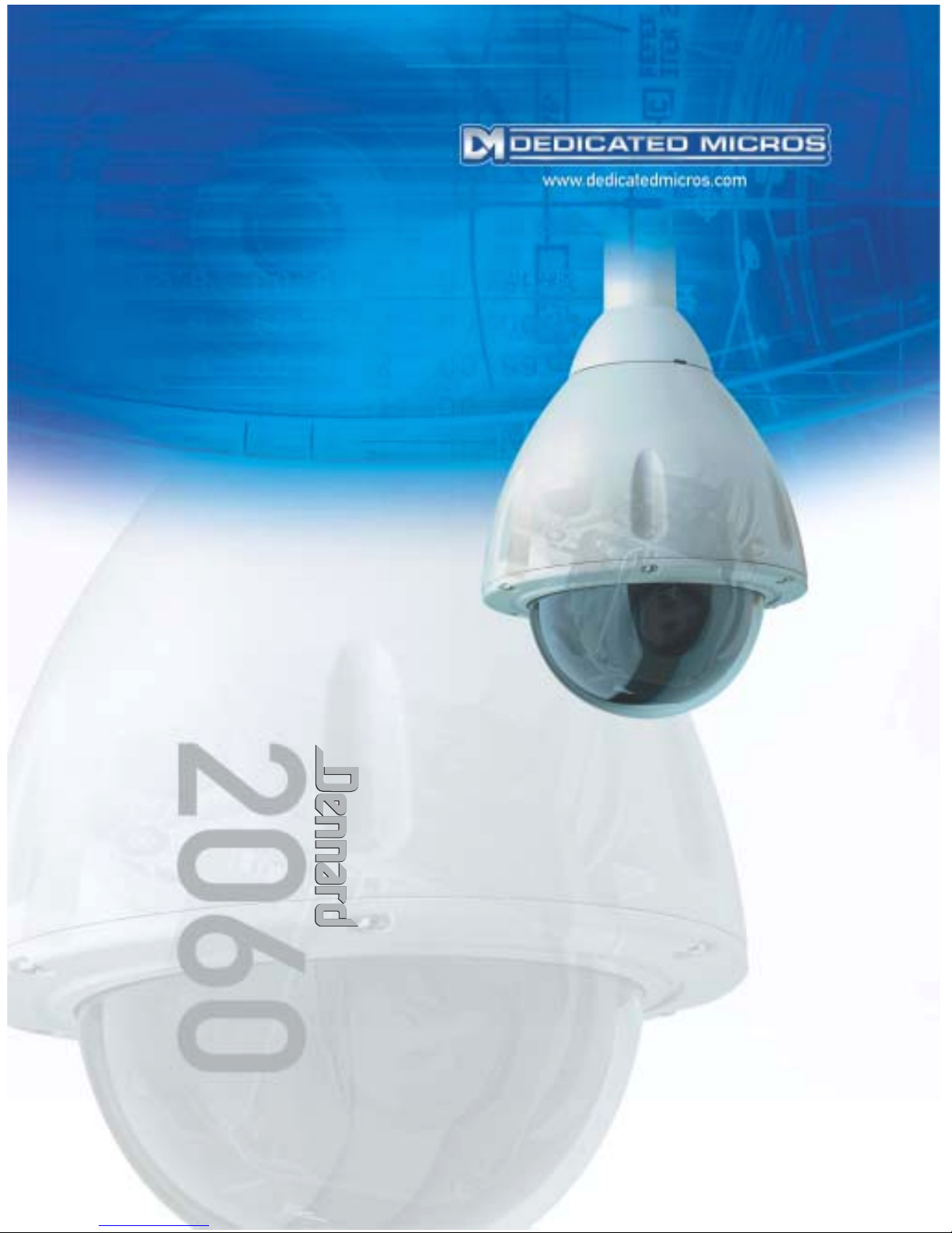
3. List of contents
Components supplied
Before installing the dome, please remove the components from the packaging
and verify that all items listed below have been supplied:
1 x Dennard 2060 Dome enclosure (with safety bond)
1 x Power supply
1 x Flying lead connector
1 x Fixing bag containing the following:
1 x 4mm A/F Hexagonal socket key
1 x 5mm A/F Hexagonal socket key (Indoor only)
4 x M6x16 Soc. Cap. Screws (Indoor only)
N.B. Mounting bracketry may have been ordered and delivered separately.
In addition to the above components, the following paperwork is supplied:
A
CD
B
- Dennard 2060 Operation Manual - Dennard 2060 quick setup guide
- Dennard 2060 Menu System Manual - Final test procedure
Dennard 2060 Operation Manual Page. 3
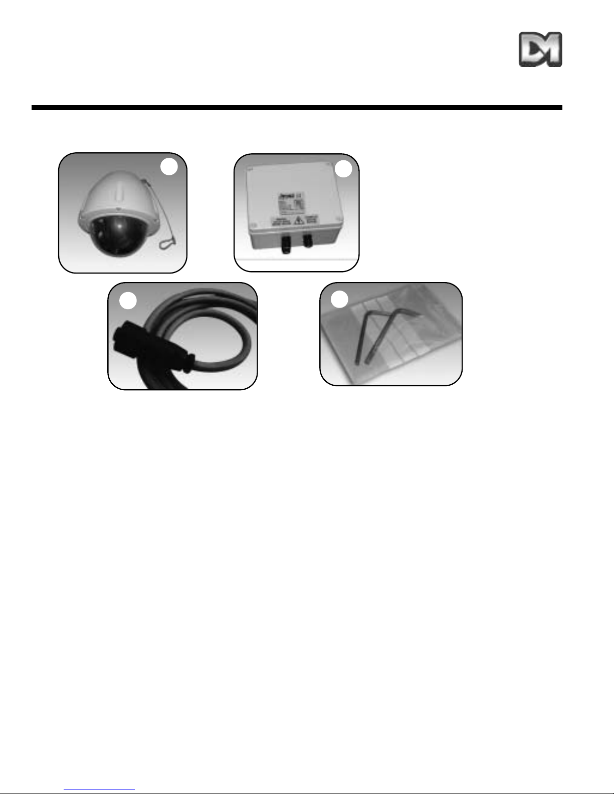
4. Mounting Configurations
With appropriate bracketry the Dennard 2060 dome enclosure can be mounted in any of the
orientations shown above.
1. Wall/Pendant Mount (order code Dennard 90002) giving pendant or wall mount options.
2. Pendant mount bracket (order code Dennard 90003) with drop length to suit customers
requirements.
3. Snowdrop mount bracket (order code Dennard 90004) for mounting at the top of a pole or
column.
4. Vintage mount bracket (order code Dennard 90005) for a vintage feel around historical
buildings.
5. Ceiling mount bracket (order code Dennard 90006) for solid or suspended ceilings.
6. Tile mount (order code Dennard 90001) for suspended ceilings.
7. Corner Bracket (order code Dennard 90007) for mounting to corners of buildings in conjunction
with Dennard 90002.
8. Extended corner bracket (order code Dennard 90008) for mounting to corners of buildings with
Dennard 90002.
9. Extended wall mount (order code Dennard 90009) for extending out from a wall.
All bracket variants can be supplied with optional rain shield (order code Dennard 90010).
All mounting variants are suitable for both weatherproof ( IP66 BS EN 60529 ) & indoor units.
1. 2. 4.
5.
8.
Fig.2 Bracket mounting variants
3.
9.
6.
7.
Dennard 2060 Operation Manual Page. 4
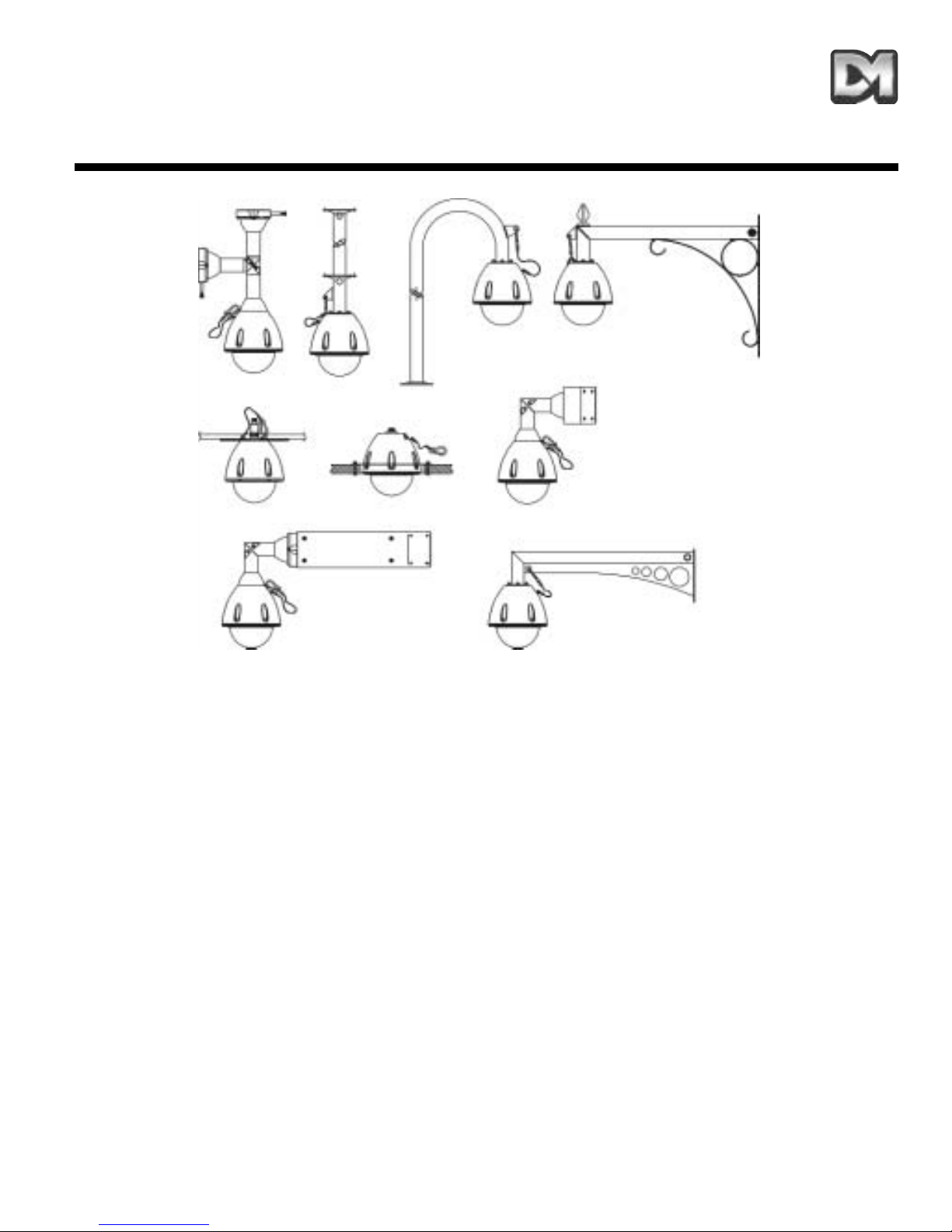
5. Safety Bond
For wall, pendant & snowdrop mounted domes (wall mount shown in Fig.3), clip carbine to the
mounting bracket eyelet (B) on flange of bracket to secure.(shown above).
For standard ceiling mounted domes attach the supplied safety bond, as shown in Fig.4. Fit bond
over M6 stud (position D) and secure with M6 nut, plain washer & spring washer supplied. Clip
carbine to eyelet (E) on dome to secure (see sheet 5 ‘Ceiling mounting instructions’ for details on
eyelet mounting).
Note: Always support dome with bond prior to mating connector (C). Weight of dome should be supported by
bond ensuring no stress is placed on centre connector (C) at any time.
Fig.3 Safety bond (Bracket mount) Fig.4 Safety bond (Ceiling mount)
B
C
E
D
B

Dennard 2060 Operation Manual Page. 5
6. Ceiling Mounting
Cut/drill hole pattern in ceiling as shown in (fig.5) (Note: fixings for hole (A) are not supplied by
Dedicated Micros due to the variation of ceiling materials / thicknesses found on site. Use suitable
M6 fixings, with countersunk head, for your application.) Attach mounting disc (B) to ceiling with
chosen fixings and screw 4 off M6 x 16 soc cap hd. screws supplied into bushes as shown (C).
Attach transfer disc (E) to top of dome enclosure (G) with 4 off M6 dome hd. self tapping trilobular
screws (D) pre-fitted (fig.6) (Note: Fit safety bond bracket (F) as shown) Offer dome enclosure to
ceiling mounting disc (fig.7) engaging the screw heads (C) into keyhole slots (G). Twist to locate
and tighten fixings (C) to secure.
Please ensure safety bond is fitted as descibed on sheet 4.
Fig. 7
Fig.5 Ceiling hole pattern
5mm
B
C
D
E
GDFG
4 x Ø6.5mm
A
Fig. 6
7. Wall Mounting Bracket
A. Remove bracket base casting by unscrewing outer trilobular fixings, then assuming masonry
wall mounting, mark & drill 4 x Ø7 holes using bracket base casting as pattern, shown above.To
assist with orientation flats are provided on all 4 axes allowing the use of a spirit level for
alignment. (Fig 8) (use goggles when drilling).
B. Insert 4 x M6 Rawlplugs into wall until flush.
C. Offer bracket base casting into position & screw wall fixing screws through into inserts.
D. Tighten fixings to secure. Note: An optional spreader plate (9011) is recommended when fixing
to brickwork to reduce the ‘pull out’ forces on a single brick.(Available from Dedicated Micros on
request).
Note: Locating a dome on a corner of a building will give an increased area of surveillance. For this application
Dedicated Micros are able to offer an optional corner bracket (9007) to adapt the standard wall bracket.
E. Thread cable from bracket through cable entry hole in bottom of bracket base casting, then fit
the bracket (Fig 9) (Note: bracket base casting can be orientated to position the entry hole to
either side or at the top.).
F. Using supplied trilobular fixings attach bracket to base casting as shown. (Fig 10).
Dennard 2060 Operation Manual Page. 6
4 x Ø7mm
22.5º
Fig.8 Bracket Base Casting
Fig. 9 Fig. 10
Wall Fixing Screws
E
F
Outer Trilobular Fixings (M6 x 16)

Dennard 2060 Operation Manual Page. 7
8. Tile Mounting
Cut/drill hole pattern in tile as shown in (fig.11).
Attach the mounting disc to the dome as shown in (fig.12) using 3 of the existing M4 dome hd. self
tapping trilobular screws, that attach the hemisphere to the dome (item A).
Offer dome complete with attached mounting disc (item B) up to the hole in the tile from beneath
and clamp to tile using 2 off split clamp rings (items C) from above.
Secure mounting disc with 4 off M6 soc button hd. fixings (supplied) (item D) as shown in (fig.13).
Fit safety bond supplied (item E) to an attachment point in ceiling.
Note: For use with soffit mount the split clamp ring needs to be fixed into position using 4 off M4 pan hd. self
tapping fixings (supplied) (item F) (fig.14).
Fig.14 Split bezel mounting
Fig.11 Ceiling hole pattern
255mm
255mm
4 x Ø7mm
Ø215mm
Fig.12 Mounting disc attachment
A
E
D
F
C
B
Fig.13 Mounting to tile (ceiling)

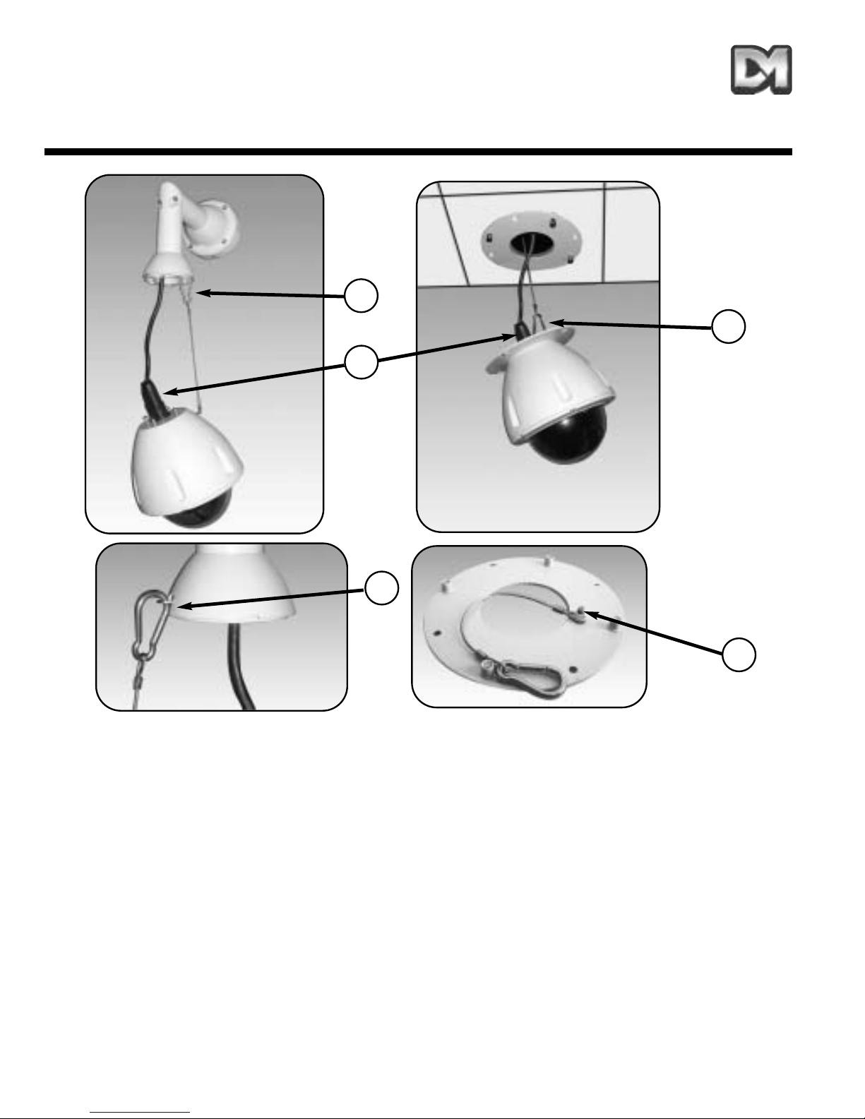
9. Dome Mounting
Fig.15 Mounting dome to bracket
A. Secure & hang dome to bracket by attaching safety bond carbine to eyelet, as shown.
BMate central connector supplying power & control to dome. (Ensure power is off when
connecting).
C. Lift dome to bracket flange ensuring head of screws (previously fitted M6x16 Trilobular self
tapping screws) pass through keyhole slots. Twist to locate.
D. Tighten 4 top mounting fixings with 4mm A/F Hexagonal key supplied to secure, finally secure
plasic cover to metal pins on bracket flange .
Dennard 2060 Operation Manual Page. 8
B
A
CD
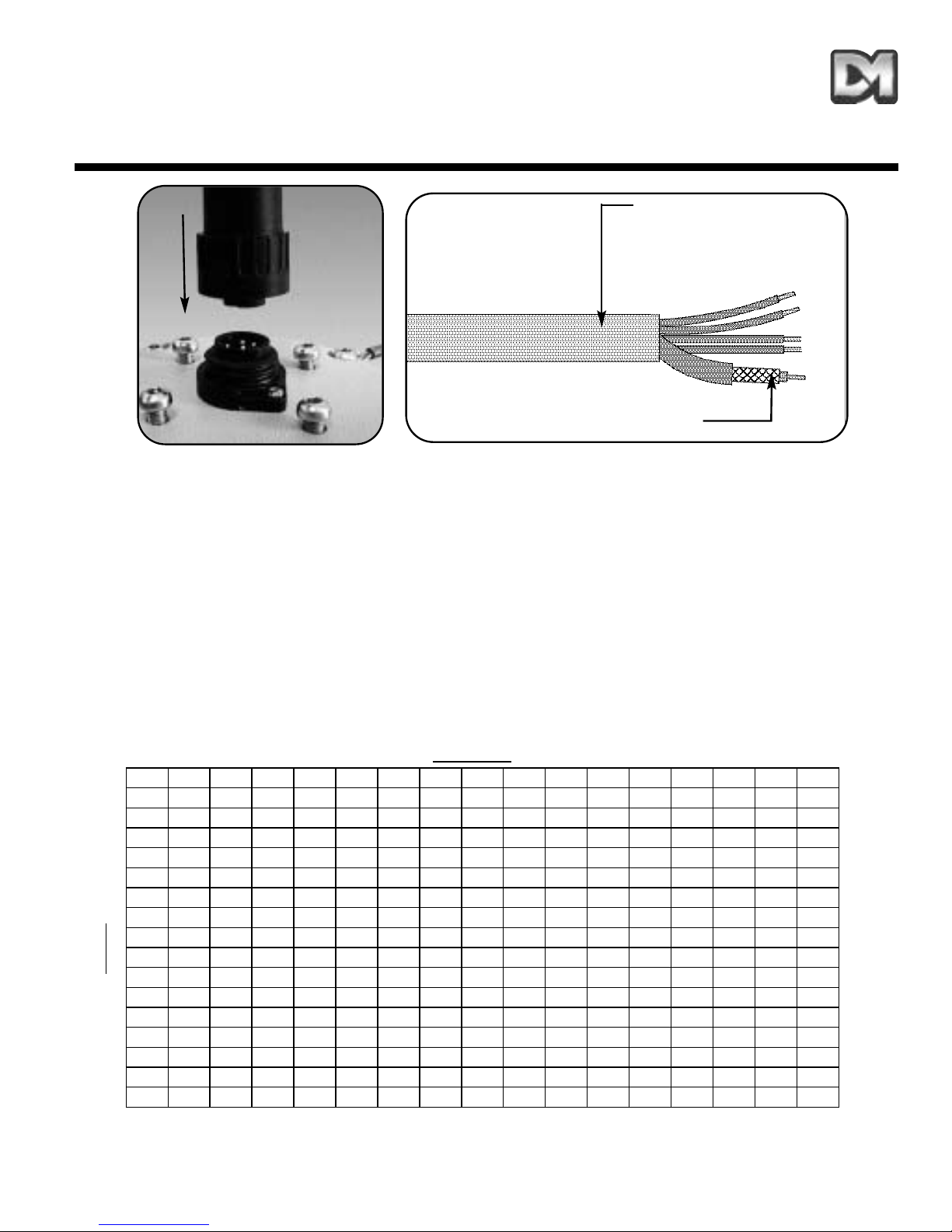
10. Electrical Connections
Fig.16 Electrical connections
The Dennard 2060 external connections are via an IP66 Amphenol connector with 3 metre
composite cable flying lead comprising co-ax, power pair & RS485 pair. This lead should be
connected to the boxed P.S.U. supplied with the dome (can be extended to 30 metres max. in
length) The connections are as follows:
The co-ax and power wires are always connected, the RS 485 wires are only connected when an
external protocol converter is fitted or an RS485 controller is being used.
Dennard 2060 Operation Manual Page. 9
Red wire....24 V AC live
Blue wire..24 V AC neutral
Yellow wire.......R.S. 485 'A'
Green wire.......R.S. 485 'B'
Coax screen.......BNC screen
Coax signal........BNC centr pin
Fig.17 Address chart
Co-ax. (Video)
Multicore cable with
integral Co-ax (Video)
YELLOW
BLUE
ADDRESS SWITCHES
0 1 2 3 4 5 6 7 8 9 A B C D E F
00 1 2 3 4 5 6 7 8 9 10 11 12 13 14 15
116 17 18 19 20 21 22 23 24 25 26 27 28 29 30 31
232 33 34 35 36 37 38 39 40 41 42 43 44 45 46 47
348 49 50 51 52 53 54 55 56 57 58 59 60 61 62 63
464 65 66 67 68 69 70 71 72 73 74 75 76 77 78 79
580 81 82 83 84 85 86 87 88 89 90 91 92 93 94 95
696 97 98 99 100 101 102 103 104 105 106 107 108 109 110 111
7112 113 114 115 116 117 118 119 120 121 122 123 124 125 126 127
8128 129 130 131 132 133 134 135 136 137 138 139 140 141 142 143
9144 145 146 147 148 149 150 151 152 153 154 155 156 157 158 159
A160 161 162 163 164 165 166 167 168 169 170 171 172 173 174 175
B176 177 178 179 180 181 182 183 184 185 186 187 188 189 190 191
C192 193 194 195 196 197 198 199 200 201 202 203 204 205 206 207
D208 209 210 211 212 213 214 215 216 217 218 219 220 221 222 223
E224 225 226 227 228 229 230 231 232 233 234 235 236 237 238 239
F240 241 242 243 244 245 246 247 248 249 250 251 252 253 254 255

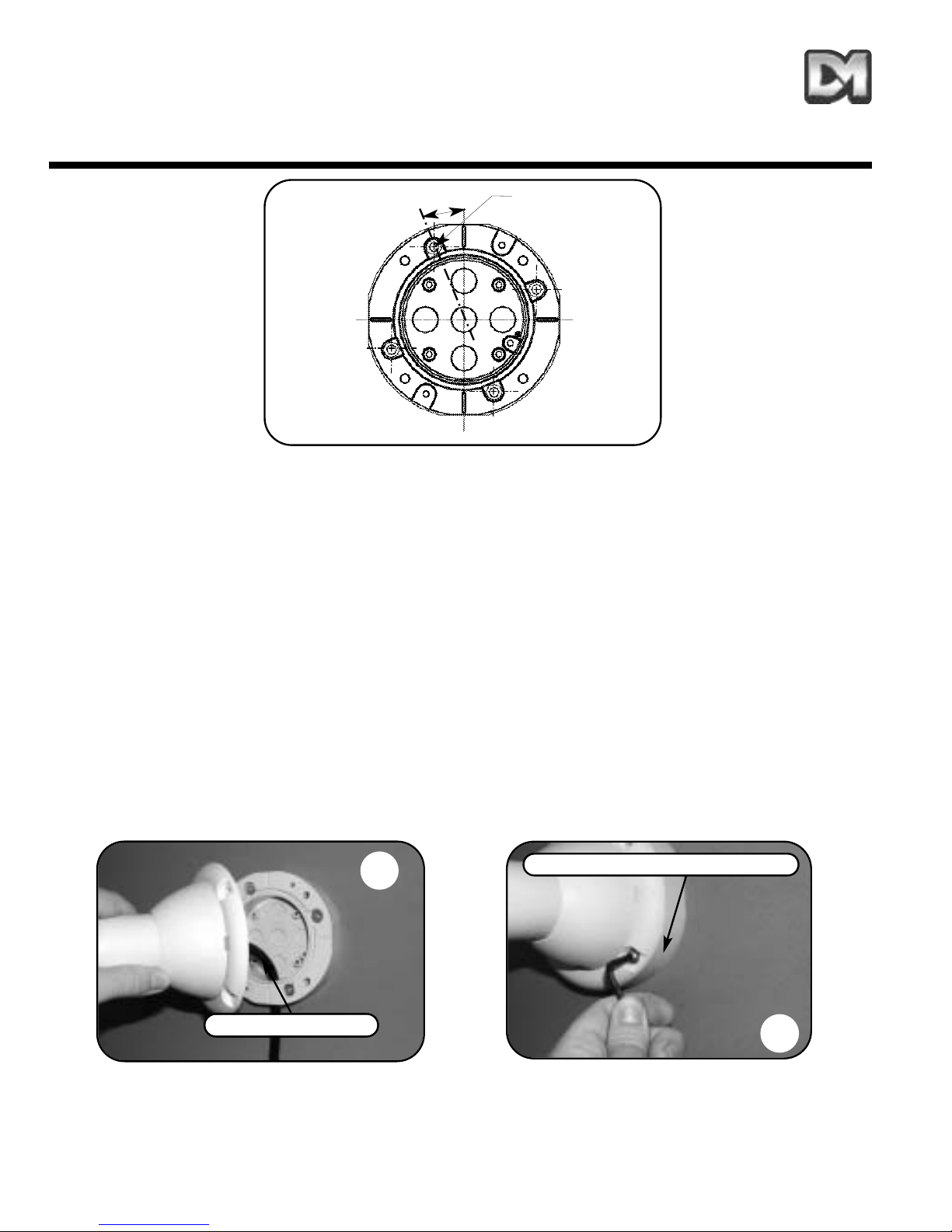
11. Address Switches
Dennard 2060 Operation Manual Page. 10
Fig.18 Address switches.
Address switches
A
C
B
Address switches
The Dennard 2060 can be controlled via RS 485
commands or ‘up the co-ax’.
With RS 485 control each dome has to be individually
addressed using the Blue and Yellow rotary address
switches following the address chart on the previous
page.
For ‘up the co-ax’ control, using the built in protocol
converter, the same address switches are used to
select the protocol format for the controller being used
e.g.
BAX AC PANEL.................Blue.F Yellow.C = 252
For: Baxall a.c. controllers
DEN PANEL.......................Blue.F Yellow.D = 253
For: Dennard, BBV & DM Sprite controllers
BAX DC PANEL................Blue.F Yellow.E = 254
For: Baxall d.c. controllers
For ‘up the co-ax’ control using external protocol
converters like the drx 100 or DAX-DEN the address
switches should be set to Blue.0 Yellow.1 = 1.
To access the address switches remove the outer
hemisphere and inner shroud as shown in A & B.
Picture C shows the location. This operation should be
carried out in an office type environment to avoid
ingress of moist air.

12. Control Configuration
Dennard 2060 Operation Manual Page. 11
Fig.19 RS485 configuration The Dennard 2060 dome can be controlled by
one of three methods.
Fig.19 RS485
Fig.20 Twisted Pair Configuration
Fig.21 Up the co-ax
The configuration drawings on this page show
the three connection arrangements.
Dennard 2060 Domes are delivered with
address switches set at ...253 (DEN PANEL)
Dennard 2060 with drx Domes are delivered
with address switches set at...1
Fig.20 Twisted Pair Configuration
Fig.21 Up the co-ax Configuration
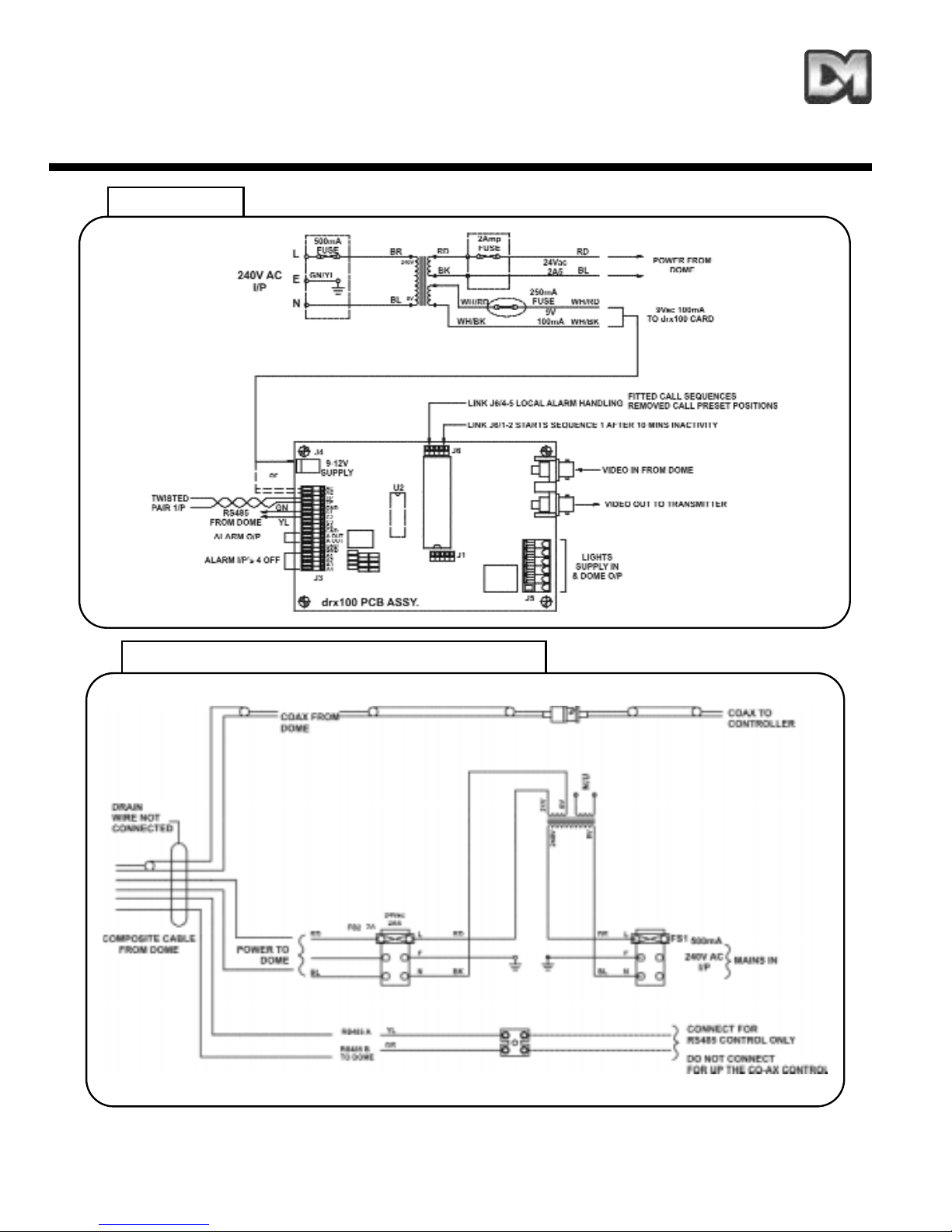
13. Circuit Diagram
Dennard 2060 Operation Manual Page. 12
RS485 / Up the Co-Ax Configuration
drx options

Dennard 2060 Operation Manual Page. 13
ADDENDUM
Addendum 1. Dennard 2060 Fixed Attitude
Dome Camera
Addendum 2. Dennard 2060 Fixed Attitude
(Electrical Connections)
Addendum 3. Dennard 2060 Fixed Attitude
(‘Zoom Cam’ Set Up)
Dennard 2060 (Fixed Attitude Dome Camera)
Dennard 2060 Operation Manual Addendum 1
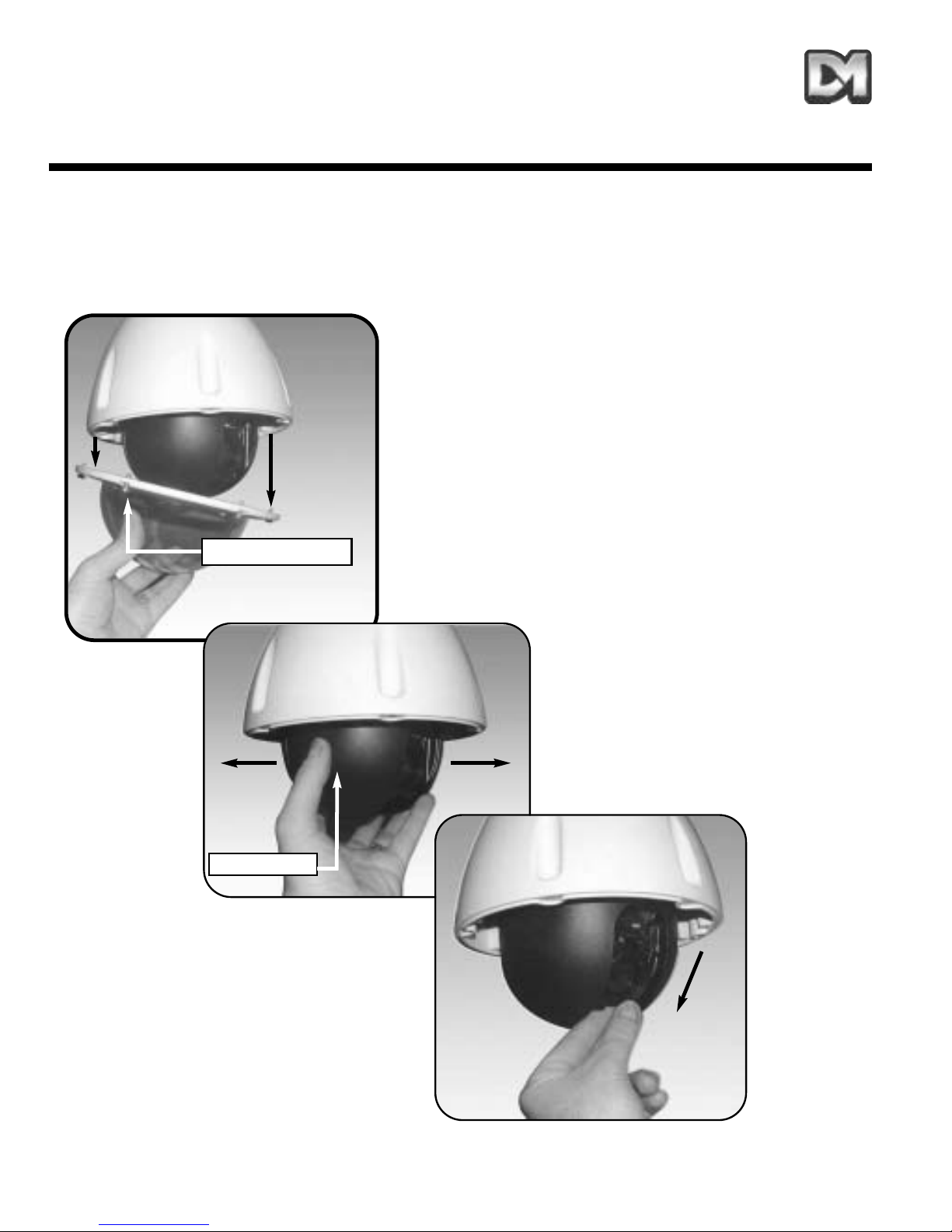
Moving cameras can be positioned remotely, fixed
attitude modules require manual adjustment to
position the camera. Follow the procedure below
to set-up your required picture frame.
1. Unscrew the 6 fixings securing the outer
hemisphere to the casing and remove.
2. To adjust the pan position of the camera, grip the
inner hemisphere and rotate. This adjustment
provides 180º of pan right & left movement. Tip. Do
not wind more than 180º in one direction as this will
stress the connections to the camera.
3. To adjust the tilt position grip the camera platform
(accessible through the camera viewing slot) as
shown and move. This adjustment provides tilt
up/down. See Addendum 3 for ‘zoom cam’ set-up.
1. Hemisphere removal
2. Camera pan adjustment
Inner hemisphere
3. Camera tilt adjustment
6 x fixing screws

Dennard 2060 (Fixed Attitude Connections)
The Dennard 2060 Fixed Attitude Camera Dome is supplied complete with an IP66 ‘Amphenol’ 7
way connector and 3 metre multicore with Co-ax flying lead assembly. The Amphenol connector
mates as shown in fig.16 to the top of the dome. The table below details the flying lead functions.
Dennard 2060 Operation Manual Addendum 2
Electrical connections
Red.... ..... 24 V AC live
Blue .........24 V AC neutral
Yellow ..... not used
Green ...... not used
Co-ax Screen ..... BNC screen
Co-ax Signal ..... BNC centre pin
P.S.U. Connection diagram
Co-ax. (Video)
Multicore cable with
integral Co-ax (Video)
Dennard 2060 (Fixed Attitude Electrical Connections)
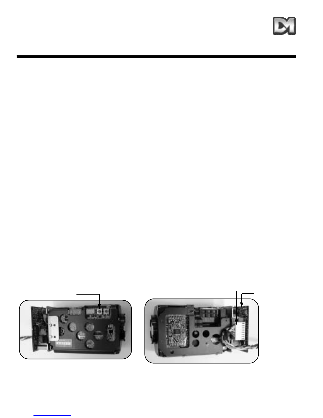
Dennard 2060 Fixed Attitude ‘Zoom Cam’ is equipped with the ‘zoom cam’ high resolution
camera. See instructions below.
1. Control
Remote zoom control requires a Dennard, BBV or DM telemetry controller. as well as the removal of link ‘A’
(see point 6) if not already disconnected. Depress the zoom buttons or use the joystick pan axis to operate. If
no control is available the camera can function as a ‘fixed lens’ (see point 6).
2. Presets
The ‘zoom cam’ can store up to 8, user definable, zoom presets within memory. Please refer to the relevant
controller instructions for preset programming.
3. Default position
After a period of inactivity (default 1min.) the ‘zoom cam’ will revert to preset 1 (wide angle if no preset stored).
On Dedicated Micros & BBV controllers only, use the ‘Patrol 2 delay program’ to adjust the time interval.
Intervals are 1,2,3,4,5,6,8 & 10 minutes for keys 1-8.
4. Patrol
The ‘zoom cam’ patrol feature can be used to sequence between the preset positions. Follow the relevant
controller instructions to setup ‘Patrol 1.’ Patrol mode is cancelled with any manual zoom action.
5. Video level adjustment
Video level is factory set, but can be adjusted by turning VR1, located just above the link’A’ on the receiver
board (see opposite). This adjustment may be required to lighten / darken the picture depending on the
distance of co-ax required.
6. Fixed lens
When no remote control is available the ‘zoom cam’ can function as a ‘fixed lens’ (i.e. the camera can be
manually zoomed (locally) to a preset position).
a. Ensure link ‘A’ (supplied) is fitted, as shown, between pins 9 & 10 on power up.
b. Frame the preset picture required by zooming, using the buttons provided on the side of the camera.
c. Temporarily remove the link ‘A’ for a few seconds and then refit. The link must be left in permanently.
Note: to revert back to ‘zoom cam’ operation the link must be removed and power re-applied.
Dennard 2060 Operation Manual Addendum 3
zoom buttons
Link ‘A’ (shown fitted) between pins
9 & 10
Left side of camera
VR1 Video
adjustment
Right side of camera

Notes

Notes
Table of contents
Languages:


