2 Inverter type and specification
14
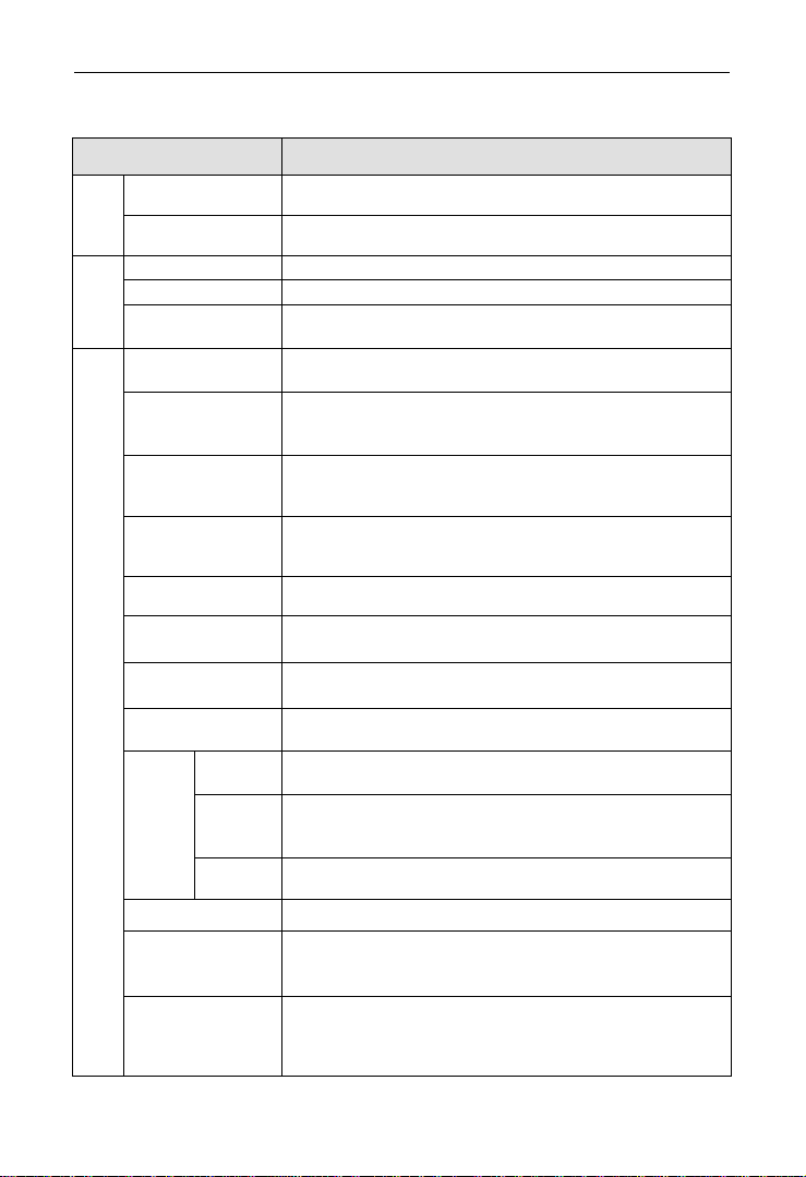
brake
Power
consumption
brake
DGI600 3 phase 15KW & under power range with inbuilt brake
unit,only add brake resistor between(+)and PB.
18.5KW & up power range is possible to add brake unit between
(+)and(-)outside; or extra connect brake unit with adding brake
resistor between(+)and PB.
DGI500 series can connect brake unit between(+)and(-)outside.
DC brake Start, stop action for option, action frequency 0~15Hz,action
current 0~100% of rated current,action time 0~30.0s
jog Jog frequency range:0Hz~up limit frequency;jog acceleration
and deceleration time 0.1~6000.0 seconds for setting.
Multi-section speed
run
Realized by inbuilt PLC or control terminal; with 15 section speed,
each section speed with separately acceleration and deceleration
time; with inbuilt PLC can achieve reserve when power down.
Inbuilt PID controller Convenient to make closed-loop control system
Automatic energy
saving run
Optimize V/F curve automatically to achieve power saving run
according to the load status.
Automatic voltage
regulate(AVR)
Automatically keep output voltage constant, when the power grid
voltage fluctuation
Automatic current
limiting
Current limited automatically under run mode in avoid of inverter
over-current frequently to trip.
carrier modulation Modulate carrier wave automatically according to the load
characteristic.
Speed tracking restart Make rotating motor smoothly start without shocking
Running function
running command
specified channel
Keypad specified, control terminal specified, communication
specified can switch through various means.
Running frequency
specified channel
Main & auxiliary specified to a realize one main adjusting and one
fine control. Digital specified, analog specified, pulse specified,
pulse width specified, communication specified and others, which
can be switched by many means at any time.
Binding function Run command channel and frequency specified channel can bind
together randomly and switch synchronously
Input output characteristic
Digital input channel
Channel 8 for universal digital input, max. Frequency 1KHz,
channel 1 can be used as pulse input channel, max. Input 50KHz,
which can be expanded to channel 14 .
Analog input channel
Channel 2 for analog input channel, AI1 can choose 4~20mA or
0~10V output,AI2 is differential input channel,4~20mA or
-10~10V for option,which can be expanded to channel 4 analog
input.
Pulse output channel 0.1 ~20KHz pulse square signal output to achieve setting
frequency, output frequency and other physical quantity output.
Analog output channel
Channel 2 for analog signal output, AO1 can choose 4~20mA or
0~10V,AO2 can choose 4~20mA or 0~10Vto achieve setting
frequency, output frequency and other physical quantity output,
which can be expanded to channel 4 analog output.