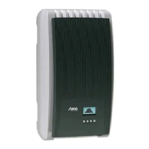
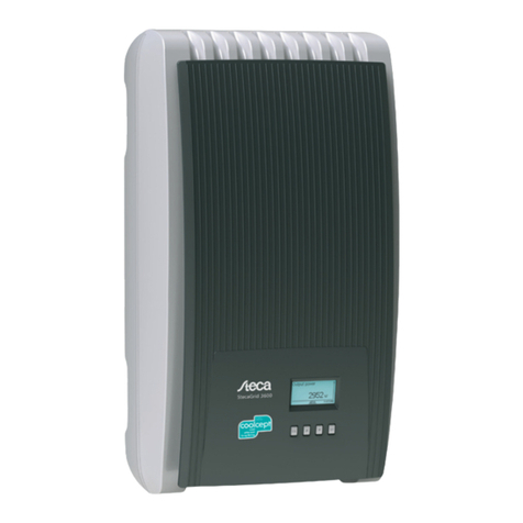
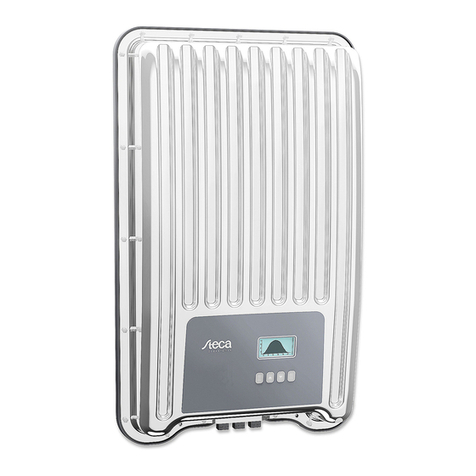
Steca coolcept fleX Series Manual

coolcept fleX
Technical Information
EN
Z02 | 1913 | 763.134

EN
2 763.134 Z02 1913 coolcept_fleX
Preface
Thank you for choosing inverters of the coolcept fleX product family of Steca Elektronik
GmbH. Through the use of solar energy, you significantly help to protect the environment
by reducing the pollution of the atmosphere by the emissions of carbon dioxide (CO2) and
other harmful gases.
Manufacturer: Steca Elektronik GmbH
Mammostrasse 1
87700 Memmingen, Germany
www.steca.com
Phone: 49 (0) 8331 85 58-0
Fax: 49 (0) 8331 85 58-131
Edition: Z02 | March 2019

EN
763.134 Z02 1913 coolcept_fleX 3
Table of contents
1General information ...................................................................6
1.1 Types....................................................................................................................6
1.2 Accessories ..........................................................................................................6
1.3 Documents ...........................................................................................................6
1.4 Monitoring portal...................................................................................................6
1.5 Scope of delivery ..................................................................................................7
1.6 Labelling ...............................................................................................................7
1.7 Type plate.............................................................................................................7
1.8 EU Declaration of Conformity ...............................................................................8
1.9 Abbreviations........................................................................................................8
2Safety ..........................................................................................9
2.1 General safety instructions ...................................................................................9
2.2 Designated use...................................................................................................10
2.3 Target group .......................................................................................................10
2.4 Labels and symbols............................................................................................11
2.4.1 Safety marks.......................................................................................................11
2.4.2 Keywords............................................................................................................11
2.5 Safety symbols on the device .............................................................................12
3Structure and functioning........................................................12
3.1 Structure of the inverter ......................................................................................12
3.2 Connections........................................................................................................13
3.3 Operating buttons ...............................................................................................13
3.3.1 Functions of the operating buttons......................................................................13
3.4 Display................................................................................................................14
3.5 Cooling ...............................................................................................................15
3.6 Grid monitoring ...................................................................................................15
3.7 Data ....................................................................................................................15
3.7.1 Data communication...........................................................................................15
3.7.2 Data display........................................................................................................16
3.7.3 Data storage .......................................................................................................16
3.8 Network (TCP/IP)................................................................................................16
3.9 "COM1" and "COM2" connections......................................................................17
3.9.1 Connecting further master devices .....................................................................17
3.9.2 Connecting further inverters ...............................................................................18
3.9.3 Fehler! Textmarke nicht definiert.
3.9.4 Alternative RS485 data connecting cable...........................................................19
3.9.5 RS485 termination..............................................................................................20
3.9.6 RS485 addressing ..............................................................................................20
3.9.7 Connecting an energy meter (Modbus RTU) ......................................................20
3.9.8 Remote shutdown by the grid operator and rapid shutdown
"Teledistacco" (Italy) ...........................................................................................21

EN
4 763.134 Z02 1913 coolcept_fleX
4Installing the inverter ...............................................................22
4.1 Safety instructions for installation .......................................................................22
4.2 Mounting the inverter..........................................................................................23
4.2.1 Attaching the mounting plate ..............................................................................23
4.2.2Fixing the inverter to the mounting plate.............................................................24
4.3 Preparing AC connection....................................................................................24
4.3.1 Selecting AC cable .............................................................................................24
4.3.2 Residual current circuit breaker ..........................................................................25
4.3.3 Assembling the AC plug .....................................................................................25
4.4 Preparing DC connection....................................................................................28
4.4.1 Fitting cable to DC plug ......................................................................................28
4.4.2 Preparing data connecting cable ........................................................................28
4.5 Connecting inverter and switching AC on ...........................................................29
4.6 Performing initial commissioning ........................................................................29
4.7 Setting the feed-in management.........................................................................30
4.7.1 Switching the energy meter on or off ..................................................................30
4.7.2 Limiting the dynamic feed-in value......................................................................30
4.7.3 Selecting an energy meter..................................................................................30
4.8 Switching DC on .................................................................................................31
5Initial commissioning...............................................................31
5.1 Setting the display language...............................................................................31
5.2 Setting the date and time....................................................................................32
5.3 Setting the country..............................................................................................32
5.4 Setting the reactive power ..................................................................................33
5.4.1 Setting the mode.................................................................................................33
5.4.2 Changing parameters of the nodes.....................................................................34
5.4.3 Displaying the reactive power characteristic curve .............................................34
5.5 Finishing the initial commissioning......................................................................34
6Dismounting the inverter .........................................................35
6.1 Switching AC and DC off ....................................................................................35
6.2 Disconnecting DC connection from inverter........................................................35
6.3 Disconnecting AC plug from inverter ..................................................................35
6.4 Opening the AC plug ..........................................................................................36
6.5 Removing inverter from mounting plate..............................................................36
7Operation ..................................................................................37
7.1 Menu structure....................................................................................................37
7.2 Navigating the menu structure............................................................................38
7.3 Status displays....................................................................................................38
7.3.1 Displaying output power .....................................................................................38
7.4 Main menu..........................................................................................................39
7.4.1 Displaying yields.................................................................................................39
7.4.2 Generator characteristic curve............................................................................39
7.4.3 Event log.............................................................................................................39
7.4.4 Information..........................................................................................................40
7.4.5 Self-test (only Italy).............................................................................................41
7.4.6 Settings...............................................................................................................42
7.4.7 Service................................................................................................................45

EN
763.134 Z02 1913 coolcept_fleX 5
8Web portal ................................................................................ 48
9Fault elimination.......................................................................49
9.1 Event message type ...........................................................................................49
9.2 Alerting behaviour...............................................................................................50
9.3 Operation............................................................................................................50
9.4 Event messages .................................................................................................50
10 Maintenance and care.............................................................. 56
10.1 Maintenance .......................................................................................................56
10.2 Care....................................................................................................................56
10.2.1 Removing dust....................................................................................................56
10.2.2 Cleaning .............................................................................................................56
11 Disposal ....................................................................................56
12 Technical data ..........................................................................57
12.1 StecaGrid 1511, 2011, 2511, 3011 and 3611.....................................................57
12.2 StecaGrid 3011_2, 3611_2 and 4611_2.............................................................60
13 Table of countries .................................................................... 62
14 Liability, warranty..................................................................... 62
15 Contact...................................................................................... 63
16 Annex ........................................................................................63
16.1 Drilling pattern for wall mounting.........................................................................63

EN
6 763.134 Z02 1913 coolcept_fleX
1 General information
These instructions contain information for the safe use of the inverter and all the infor-
mation that a specialist needs for setting up, and the operator needs for operating the in-
verter. When installing other components (e.g. PV generator, wiring), follow the instructions
of the respective manufacturer.
The coolcept fleX inverters are available in various models for different power classes.
The StecaGrid #### inverters are suitable for the connection to one PV generator.
The StecaGrid ####_2 inverters are suitable for the connection to two PV generators.
1.1 Types
The coolcept fleX inverters are available in the following models:
•StecaGrid 1511
•StecaGrid 2011
•StecaGrid 2511
•StecaGrid 3011
•StecaGrid 3611
•StecaGrid 3011_2
•StecaGrid 3611_2
•StecaGrid 4611_2
1.2 Accessories
Ask for possible accessories, options, suitable PV generators, and installation material at
the installer's or at Steca.
1.3 Documents
Data sheets, drawings, country tables, and certificates are available in the download area
of the STECA homepage.
1.4 Monitoring portal
Steca's monitoring portal sunCloud offers online monitoring of the PV generator at no
charge: https://steca.powerdoo.com

EN
763.134 Z02 1913 coolcept_fleX 7
1.5 Scope of delivery
1 Inverter
2 Mounting plate
3 AC plug
4 DC plug (one pair*)
5 Sealing cap (3 units)
6 Quick guide
* coolcept fleX ####_2: two pairs
1.6 Labelling
1 Type plate
2 Safety marks
1.7 Type plate
1 Manufacturer address
2 "Protection Class II" symbol
3 Technical data of the AC output
4 Standard for grid monitoring
5 Country-specific characteristic
6 Barcode (for internal purposes)
7 Device topology
8 Degree of protection
9 Technical data of the DC input
10 Item number and product name
Only for Australia: cover the "Protection Class II" symbol (2) on the type
plate.

EN
8 763.134 Z02 1913 coolcept_fleX
1.8 EU Declaration of Conformity
The products described in this document comply with the applicable European directives.
The certificate is available in the download area of our homepage.
1.9 Abbreviations
Abbreviation
Description
AC Alternating Current
DC Direct Current
DHCP Dynamic Host Configuration Protocol (automatic connection of the
device to an existing network)
DNS Domain Name System (name of the IP address)
LAN Local Area Network
MAC Media Access Control (device address)
MPP Maximum Power Point
MPP tracker Regulates the power of the connected module strings to the MPP
MSD Mains monitoring with allocated Switching Devices (internal grid
monitoring of the inverter)
PV Photovoltaics (technology for the conversion of solar energy into
electrical energy)
RTU Remote Terminal Unit
SELV Safety Extra Low Voltage
TCP/IP Transmission Control Protocol/Internet Protocol
URL Uniform Resource Locator (internet address)

EN
763.134 Z02 1913 coolcept_fleX 9
2 Safety
NOTE
Any repair work may only be carried out by the manufacturer's customer
service department.
2.1 General safety instructions
•This document must be kept to hand at the site of use of the inverter.
In case of a change of ownership pass on the document with the inverter.
•This document must have been read and understood in full before installing and using
the inverter.
•Incorrectly connected components may cause damage to the inverter.
•If one of the following components is damaged, immediately take the inverter out of
operation and disconnect it from the grid and the PV generators:
- Inverter (not functioning, visible damage, smoke, penetration of liquid etc.)
- Cables
- PV generators
•Do not switch on the system again until it has been repaired and checked by a suitably
qualified and authorised technical specialist.
•Dangerous voltages may be present for up to 10 minutes after disconnecting the in-
verter from the voltage sources.
•Disconnect inverter from both voltage sources (power grid and PV generator) prior to
any work on the inverter.
•Always carry out the measures described in this document in the specified sequence.
•Do not change nor remove any factory-applied labels on the inverter.
•Do not open the inverter. Danger to life! Opening the inverter will also void any warranty.
•Do not cover the inverter.
•Keep children away from the inverter.
•Follow the instructions of manufacturers of the connected components.
•Follow the general and national safety and accident prevention regulations.
The inverter does not cause any inrush current.

EN
10 763.134 Z02 1913 coolcept_fleX
2.2 Designated use
The coolcept fleX inverters are intended for single-phase feed-in and are suitable for indoor
and outdoor (degree of soiling 3) installation. The inverters are designed for wall mounting.
•Only use the inverter for grid-connected PV generators.
•The inverter is suitable for PV generators whose connections are not grounded.
•All connected solar modules must be classified as Class A according to IEC 61730,
because these inverters do not have galvanic isolation.
•The maximum permissible system voltage of the PV generator must be higher than the
AC grid voltage.
•The installation location for the inverter must not be at an altitude higher than 2000 m
above MSL.
NOTE
Only for Australia: the inverter may only be operated as a single device. It is
not permitted to interconnect several devices.
NOTE
Only for Italy: information about the particularities for the use in Italy have
been added to the Italian version of the installation and operating instruc-
tions.
2.3 Target group
Unless otherwise noted, the target group for these instructions are specialists and system
operators. The following persons are considered specialists:
•Persons that have knowledge of the established terms and skills for setting up and
operating PV generators.
•Persons that due to their knowledge and experience are able to evaluate the following
tasks and recognise possible hazards:
- Mounting electrical equipment
- Assembling and connecting data cables
- Assembling and connecting power supply cables

EN
763.134 Z02 1913 coolcept_fleX 11
2.4 Labels and symbols
2.4.1 Safety marks
The following safety marks are used on the inverter and in these instructions:
Warning sign Nature of the danger
Warning of hazardous voltage
Warning of hazardous area
Follow the instructions
2.4.2 Keywords
The following keywords are used in these instructions:
Keyword Meaning
DANGER Indicates a hazardous situation which, if not avoided, leads to death or
serious injuries.
WARNING Indicates a potentially hazardous situation which, if not avoided, may
lead to death or serious injuries.
NOTE Indicates a potentially hazardous situation which, if not avoided, may
lead to damage to property and/or the environment.

EN
12 763.134 Z02 1913 coolcept_fleX
2.5 Safety symbols on the device
1 Disposal information (separate collection of electrical and
electronic equipment)
2 Request to disconnect the power sources prior to any
intervention
3 Information on presence of voltage after switching off the
inverter
4 Serial number (barcode and plain text)
5 Warning of voltage (two voltage sources)
6 Warning of hot surface
7 Follow the instructions
3 Structure and functioning
The coolcept fleX inverter is connected between PV generators and consumers. Via the
DC input and the MPP tracker, PV generators feed in DC, which the inverter converts into
AC. Consumers connected to the AC connection are supplied AC by the inverter.
3.1 Structure of the inverter
1 Case
2 Display (monochrome, 128 x 64 pixels)
3 Operating buttons: ESC, , , SET (from left to right)
4 RJ45 sockets (LAN, COM1, COM2)
5 AC connection
6 DC connection (DC input, MPP tracker)
7 DC connection (StecaGrid ####_2: 2 x DC-input,
2 x MPP tracker)
8 DC disconnector (interrupts the plus and minus inputs
simultaneously)
9 Type plate, serial number, warning notices

EN
763.134 Z02 1913 coolcept_fleX 13
3.2 Connections
1 TCP/IP connection (LAN)
2 RS485 connection (COM1)
3 Modbus RTU connection (COM2)
4 AC connection
5 DC connection
6 DC connection (StecaGrid ####_2)
7 DC disconnector
3.3 Operating buttons
1 SET
2
3
4 ESC
3.3.1 Functions of the operating buttons
Button
Action
Function
Normal operation Commissioning
ESC Press briefly - Jumps 1 menu level up
- Discards changes
Jumps 1 step back
Press longer
(≥ 1 second)
Jumps to the start image Jumps to the start of the
guided operation
Press briefly - Moves the selection bar or the display content upwards
- Moves the selection bar 1 position to the left when setting
numeric values
- Increases the setting value by 1 step
Browses in menu structure -
Press longer
(≥ 1 second)
Triggers a repetition of the command. The repetition rate
increases when pressing for a longer period

EN
14 763.134 Z02 1913 coolcept_fleX
Button
Action
Function
Normal operation
Commissioning
Press briefly - Moves the selection bar or the display content
downwards
- Moves the selection bar 1 position to the right when
setting numeric values
- Decreases the setting values by 1 step
Browses in menu structure -
Press longer
(≥ 1 second)
Triggers a repetition of the command. The repetition rate
increases when pressing for a longer period
SET Press briefly - Jumps down by 1 menu
level
- Jumps to the diagram
view in certain menus
-
- A selected value starts flashing and can be changed
- Accepts any entered changes
- Changes the state of a control element (check box / radio
button)
Press longer
(≥ 1 second)
Answers a query dialogue
with Yes
Navigates 1 step forward
3.4 Display
At very low temperatures, the display may respond more slowly than usual.
The display shows the menus of the inverter (for an overview of the menus refer to section
7.1).
As a general rule, the menu name is located in the top left corner, and the corresponding
values or selection lines underneath.

EN
763.134 Z02 1913 coolcept_fleX 15
The backlight of the display is switched on by pressing any button. The operating states of
the inverter are shown as follows:
Display Meaning
The inverter is processing large data volumes.
It is not possible to enter user data
Backlight flashing red
with event message
Fault
3.5 Cooling
The inverter may heat up during operation. This is a normal operating characteristic.
When the internal temperature rises above a certain value, an internal temperature control-
ler regulates the power consumption from the PV generator. The operating temperature
decreases when power consumption is lower.
A fan disperses the waste heat inside the closed case evenly onto the case surface.
Cooling fins allow the heat to dissipate to the surrounding.
3.6 Grid monitoring
The grid monitoring in the device permanently monitors the grid parameters of the public
grid. If the grid monitoring detects a deviation of the grid parameters from the statutory re-
quirements, the device switches off automatically. When the public grid meets the statutory
requirements again, the device switches on again automatically.
3.7 Data
3.7.1 Data communication
The device has the following communication interfaces:
•"LAN" connection (Ethernet for TCP/IP network) for the communication with a central
data server
•"COM2" connection (Modbus RTU) for the communication with e.g. an external energy
meter
•"COM1" connection (RS485 bus) for the communication with external devices, e.g. with
a data logger (in the case of StecaGrid ####_2: two connections)
For data analysis purposes, the inverter can provide a wide range of data via the RS485
and LAN interfaces (e.g. data logger). The RS485 bus also allows the connection to other
inverters.

EN
16 763.134 Z02 1913 coolcept_fleX
3.7.2 Data display
The following data are shown on the display:
•voltage and current generated by the PV generator
•power and current fed into the public grid
•current voltage and frequency of the public grid
•generated energy yields on a daily, monthly and annual basis
•current error states and notes
•Information on the version of the device
3.7.3 Data storage
In the internal memory (EEPROM), event messages and energy yields are stored with the
date. The energy yields are stored for the specified period.
Energy yield Storage resolution/period
10-minutes values 31 days
Daily values 13 months
Monthly values 30 years
Annual values 30 years
Total yield Permanent
3.8 Network (TCP/IP)
Via the "LAN" connection, the device can send yield data and event messages to the
server of a web portal. The "Stecagrid Portal" web portal
(https://www.steca.com/index.php?Steca-sunCloud-Registration) allows the graphical rep-
resentation of the yield data.
In "Settings" > "Network", the operator can enter the network parameters in further sub-
menu masks (refer to section 7.4.6).

EN
763.134 Z02 1913 coolcept_fleX 17
3.9 "COM1" and "COM2" connections
The inverter can communicate with other device via the "COM1" and "COM2" connections.
Requirements for the communication:
•Both ends of the data connection are terminated.
•RJ45 standard cables or alternative data connecting cables are used as bus cables.
3.9.1 Connecting further master devices
Set an external data logger prior to the connection. Follow the instructions of
the manufacturers.
Optionally, one of the following master devices can be connected to the "COM1" connec-
tion. These devices support the transfer protocol of the inverter.
•StecaGrid SEM, Smart Energy Manager:
- Interface to a ripple control receiver for a feed-in management that is in accordance
with the Renewable Energy Sources Act or EEG (German: Erneuerbare-Energien-
Gesetz)
•PC or notebook (with related software):
- Read inverter information out with "StecaGrid User Software"
(https://www.steca.com/index.php?StecaGrid-User-en).
- Connection to the inverter possible via optional RS485 adapter => USB; the adapter
is available at Steca, with part number 746.610 (IP21) or 737.707 (IP65).
- Transmission of firmware updates (only specialists).
•External data logger for professional system monitoring (recommended by Steca):
- WEB’log (Meteocontrol)
- Solar-Log (Solare Datensysteme)
- Energy-Manager (Kiwigrid GmbH)

EN
18 763.134 Z02 1913 coolcept_fleX
3.9.2 Connecting further inverters
Inverters connected via the "COM2" connection operate as slave devices. RJ45 standard
cables (patch cables) for outdoor installation are suitable connecting cables.
The following inverters have compatible data interfaces and can be con-
nected as slaves to the "COM1" and "COM2" connections:
- StecaGrid 2020
- StecaGrid 1500, 1800, 2000, 2300, 2500, 3010
- StecaGrid 3000, 3600, 4200 and StecaGrid 1500, 1800x
- StecaGrid 2000x, 2300x, 2500x, 3010x, 3000x, 3600x, 4200x
- StecaGrid 1511, 2011, 2511, 3011, 3611, 3011_2, 3611_2, 4611_2
Follow the instructions on addressing, termination, and approved data cables
in the operating instructions of these devices.
1 External data logger
2 First inverter
3 Inverter
4 Last inverter, terminated
5 RJ45 standard cable (patch cable)

EN
763.134 Z02 1913 coolcept_fleX 19
3.9.3 Alternative RS485 data connecting cable
NOTE
Voltage may cause property damage.
►Only have specialists manufacture the alternative data connecting cable.
Use a CAT 5 cable for the alternative data connecting cable in the case of long data con-
necting distances.
The total length of the data connecting cable shall exceed 1000 m.
If the alternative data connecting cable is connected to the RJ45 socket of the first inverter
and to the connection of the external data logger, the connections in the plug must be as-
signed in accordance with the following table.
Plug assignment of alternative RS485 data connecting cable
Device
Inverter
Solar-Log
WEB’log
1)
Kiwigrid
Signal
Connection
COM1/COM2
Terminal block
RJ12
Terminal
block
Contact
1 1 2 A Data A
2 4 4 B Data B
3 - - - -
4 - - - -
5 - - - -
6 - - - -
7 - - - -
8 3 6 GND Ground
NOTE
1) Contact 1 of the RJ12 socket supplies 24 V DC!
The RS485 input of the inverter may be damaged.
►Never connect the alternative data connecting cable to contact 1.

EN
20 763.134 Z02 1913 coolcept_fleX
3.9.4 RS485 termination
Terminate the data connection at its beginning and at its end to ensure faultless data trans-
mission:
•Beginning of the data connection: terminate external data logger in accordance with the
manufacturer's instructions.
•End of the data connection: insert termination plug into the vacant RS485 interface of
the last inverter.
3.9.5 RS485 addressing
All inverters are set to address "1" at the factory. For the master-slave communication,
each inverter requires its own address. The address is changed in the menu under "Set-
tings" > "RS485 address".
•If possible, assign the addresses starting with 1 at the first inverter and ascending to the
last, as the number of possible addresses in the inverters is limited.
•The sequence of addresses should mirror the order of the mounted devices, to facilitate
the identification of the devices.
3.9.6 Connecting an energy meter (Modbus RTU)
The inverter is able to communicate with energy meters via the "COM2" connection. To do
this, the energy meter must meet the following requirements:
•The energy meter has been preprogrammed in the inverter.
•The energy meter measures the draw from the grid in positive direction (refer to instruc-
tions of the energy meter).
Modbus RTU data connecting cable
NOTE
Voltage may cause property damage.
►Only have specialists manufacture the alternative data connecting cable.
Use a RJ45 standard cable or a CAT5 patch cable as data connecting cable.
This manual suits for next models
8
Table of contents
Other Steca Inverter manuals

Steca
Steca Fronius Solarix 400 I User manual

Steca
Steca coolcept StecaGrid 1500 User guide

Steca
Steca Solarix PI 500-12 User manual

Steca
Steca stecagrid 300 User manual

Steca
Steca coolcept User manual

Steca
Steca coolcept3 StecaGrid 3203 User manual

Steca
Steca StecaGrid 1900 Series User manual

Steca
Steca StecaGrid 8 000+ 3ph User manual

Steca
Steca Solarix 2020-x2 User manual

Steca
Steca XPC 1400-12 Use and care manual