degewo Pyrexx PX-1 User manual

Instruction manuel
All information regarding the
smoke detector model Pyrexx PX-1
Photo: Pyrexx Mediathek

2 I 32
PX-1Rauchwarnmelder
Smoke Alarm Device
Betriebsanleitung
Operating Manual 2
Die Originalfassung dieser Anleitung ist
nach DIN EN 82079-1 in deutscher Spra-
che erstellt.
The original version of this instruction has
been prepared in German in accordance
with DIN EN 82079-1.
Inhaltsverzeichnis
1 Hinweise zur Betriebsanleitung 3
2 Sicherheitshinweise 6
3 Übersicht 11
4 Standortauswahl 13
5 Montage 20
6 Inbetriebnahme 23
7 Stör- und Fehlermeldungen 24
8 Instandhaltung 26
9 Außerbetriebnahme 28
10 Zubehör, Ersatzteile und
Produktsupport 29
11 Technische Daten 55
12 Alarm- und Hinweistöne 57
Content
1 Notes on the operating manual 30
2 Safety instructions 33
3 Overview 37
4 Location selection 39
5 Installation 44
6 Putting into operation 48
7 Fault and error messages 48
8 Maintenance 51
9 Decommissioning 53
10 Accessories, spare parts and
product support 54
11 Technical speci�cations 55
12 Alarm and alert tones 57
3
Betriebsanleitung: PX-1 - Rauchwarnmelder
1 Hinweise zur
Betriebsanleitung
Wir freuen uns, dass Sie sich für unser
Produkt entschieden haben und danken
Ihnen für Ihr Vertrauen!
Die vorliegende Betriebsanleitung enthält
Informationen und Hinweise zur sicheren
Montage, Inbetriebnahme und Instand-
haltung, sowie zum einwandfreien Betrieb
des Rauchwarnmelders.
Die Betriebsanleitung muss zwingend ge-
lesen und verstanden werden.
Für eine bessere Lesbarkeit wird der PX-I
Rauchwarnmelder im weiteren Fließtext
als „Rauchwarnmelder“ bzw. „Gerät“
bezeichnet.
1.1 Gültigkeit der
Betriebsanleitung
Die Betriebsanleitung gilt nur für Rauch-
warnmelder des Typs PX-I mit oder ohne
Q-Label.
1.2 Typenschild und Identi�kation
Das Typenschild des Rauchwarnmelders
be�ndet sich unter der Prüf-/Stopp-Taste
(Abdeckung Rauchwarnmelder).
Rauchwarnmelder ohne Q-Label
Ein Rauchwarnmelder ohne Q-Label ist
nicht nach vfdb-Richtlinie 14/01 zerti�zier t.
Rauchwarnmelder mit Q-Label
Einen Rauchwarnmelder mit Q-Label er-
kennen Sie am auf demTypenschild.
1.3 Konformität
Der Rauchwarnmelder desTyps PX-I ohne
Q-Label ist zerti�ziert nach:
•Verordnung (EU) Nr. 305/2011
gemäß EN 14604:2005/AC:2008
4Betriebsanleitung: PX-1 - Rauchwarnmelder
Der Rauchwarnmelder des Typs PX-I mit
Q-Label ist zerti�ziert nach:
•vfdb-Richtlinie 14/01 (Q)
•Verordnung (EU) Nr. 305/2011
gemäß EN 14604:2005/AC:2008
Nähere Informationen zum Q-Label und
der vfdb-Richtlinie �nden Sie auf unserer
Homepage unter pyrexx.com.
Konformität gemäß
EN 14604:2005/AC:2008 (CE)
Der Rauchwarnmelder ist nach Ver-
ordnung (EU) Nr. 305/2011 gemäß
EN 14604:2005/AC:2008 (CE) als Bau-
produkt zerti�ziert. Die Produktion wird
durch regelmäßige und unabhängige Kon-
trollen auf unveränderte Einhaltung der
gesetzlichen und normativen Vorgaben
überwacht.
Die Leistungserklärung für einen Rauch-
warnmelder ohne Q-Label ist unter
folgender Bezugsnummer beim Hersteller
abrufbar: co_1055
Die Leistungserklärung für einen Rauch-
warnmelder mit Q-Label ist unter
folgender Bezugsnummer beim Hersteller
abrufbar: k_76679
1.4 Aufbewahrung der
Betriebsanleitung
Die Betriebsanleitung ist ein wichtiger
Bestandteil des Rauchwarnmelders und
muss in der Nähe des Montageortes stets
griffbereit aufbewahrt werden.

3 I 32
29
Betriebsanleitung: PX-1 - Rauchwarnmelder
10 Zubehör, Ersatzteile
und Produktsupport
•Pyrexx Montagestab mit
Krallenkrone (für Dienstleister)
•RWM MC (Diagnosegerät) für
einen erweiterten Funktionstest
(für Dienstleister)
•Abdeckung Rauchwarn-
melder (Dekodeckel)
•Magnetträger mit Klebepad
•Klebefolie
•Splint (Aktivierungssicherung)
•Schraube/Dübel-Beutel
10.3 Produktsupport
Im Garantie- bzw. Gewährleistungsfall
übersenden Sie das Gerät bitte an den
Verkäufer.
Der Produktsupport ist per E-Mail un-
ter support@pyrexx.com und telefonisch
unter +49 30 8871 606 641 zu erreichen.
Erklärende Filme zu unseren Produkten
�nden Sie auf pyrexx.com/de/support/
mediathek.
30 Operating Manual: PX-1 - Smoke Alarm Device
1 Notes on the
operating manual
1.1 Scope of the operating manual
The operating manual applies only to
smoke detectors of the PX-I type with or
without “Q“ label.
1.2 Name plate and identi�cation
The name plate of the smoke alarm de-
vice is located below the testing/stop but-
ton (smoke alarm device cover).
Smoke detector without "Q" label
A smoke alarm device without “Q“ label
is not certi�ed acccording to vfdb stan-
dard 14/01.
Smoke detector with "Q" label
A smoke alarm device with “Q“ label has a
on the name plate.
We are glad that you have chosen our
product and we would like to thank you
for your trust!
This operating manual contains informa-
tion and instructions for safe assembly,
commissioning, installation and mainte-
nance, as well as proper operation of the
smoke alarm device.
The operating manual is intended to in-
crease the reliability and life cycle, and to
help avoid hazards and downtime, or a
loss of warranty claims.
It is absolutely necessary that the operat-
ing manual is read and understood.
For a better readability, the PX-I smoke
alarm device is hereinafter referred to as
“smoke alarm device” or “device”.
Operating Manual: PX-1 - Smoke Alarm Device 31
1.3 Conformity
The PX-I smoke alarm device without
“Q” label is certi�ed according to:
•Regulation (EU) No 305/2011 ac-
cording to EN 14604:2005/AC:2008
The PX-I smoke alarm device with
“Q” label is certi�ed according to:
•vfdb guideline 14/01 (Q)
•Regulation (EU) No 305/2011 ac-
cording to EN 14604:2005/AC:2008
For more information about the “Q” la-
bel and the vfdb guideline, please visit our
website at pyrexx.com.
Conformity in accordance with
EN 14604:2005/AC:2008 (CE)
The smoke alarm device is certi�ed as a
construction product in accordance with
Directive (EU) No. 305/2011 according
to EN 14604:2005/AC:2008 (CE). The
production is monitored for unchanged
compliance with legal and normative re-
quirements by periodic and independent
checks.
The Declaration of Performance for a
smoke alarm device without “Q” label is
available at the following reference num-
ber at the manufacturer: co_1055
The Declaration of Performance for a
smoke alarm device with “Q” label is avail-
able at the following reference number at
the manufacturer: k_76679
32 Operating Manual: PX-1 - Smoke Alarm Device
Warning symbol in warning labels
Additional information and
guidelines
fSymbol for an instruction or a
required action
All rights are reserved, particularly the
rights of duplication, distribution and trans-
lation. No part of these operating manual
may be reproduced in any form, or pro-
cessed, duplicated, or disseminated by
using electronic systems without written
permission of PyrexxTechnologies GmbH.
1.7 Guarantee and warranty
The Pyrexx guarantee conditions
and the statutory warranty apply. The
Pyrexx Technologies GmbH warrants a
defect-free device only for the original pur-
chaser of this product that was purchased
either at Pyrexx Technologies GmbH di-
rectly, or through an authorized reseller,
for a period of 12 years from the date
of purchase, when used and serviced as
intended.
You can �nd the Pyrexx guarantee condi-
tions at pyrexx.com/en/support/downloads
in the download area.

4 I 32
29
Betriebsanleitung: PX-1 - Rauchwarnmelder
10 Zubehör, Ersatzteile
und Produktsupport
•Pyrexx Montagestab mit
Krallenkrone (für Dienstleister)
•RWM MC (Diagnosegerät) für
einen erweiterten Funktionstest
(für Dienstleister)
•Abdeckung Rauchwarn-
melder (Dekodeckel)
•Magnetträger mit Klebepad
•Klebefolie
•Splint (Aktivierungssicherung)
•Schraube/Dübel-Beutel
10.3 Produktsupport
Im Garantie- bzw. Gewährleistungsfall
übersenden Sie das Gerät bitte an den
Verkäufer.
Der Produktsupport ist per E-Mail un-
ter support@pyrexx.com und telefonisch
unter +49 30 8871 606 641 zu erreichen.
Erklärende Filme zu unseren Produkten
�nden Sie auf pyrexx.com/de/support/
mediathek.
30 Operating Manual: PX-1 - Smoke Alarm Device
1 Notes on the
operating manual
1.1 Scope of the operating manual
The operating manual applies only to
smoke detectors of the PX-I type with or
without “Q“ label.
1.2 Name plate and identi�cation
The name plate of the smoke alarm de-
vice is located below the testing/stop but-
ton (smoke alarm device cover).
Smoke detector without "Q" label
A smoke alarm device without “Q“ label
is not certi�ed acccording to vfdb stan-
dard 14/01.
Smoke detector with "Q" label
A smoke alarm device with “Q“ label has a
on the name plate.
We are glad that you have chosen our
product and we would like to thank you
for your trust!
This operating manual contains informa-
tion and instructions for safe assembly,
commissioning, installation and mainte-
nance, as well as proper operation of the
smoke alarm device.
The operating manual is intended to in-
crease the reliability and life cycle, and to
help avoid hazards and downtime, or a
loss of warranty claims.
It is absolutely necessary that the operat-
ing manual is read and understood.
For a better readability, the PX-I smoke
alarm device is hereinafter referred to as
“smoke alarm device” or “device”.
Operating Manual: PX-1 - Smoke Alarm Device 31
1.3 Conformity
The PX-I smoke alarm device without
“Q” label is certi�ed according to:
•Regulation (EU) No 305/2011 ac-
cording to EN 14604:2005/AC:2008
The PX-I smoke alarm device with
“Q” label is certi�ed according to:
•vfdb guideline 14/01 (Q)
•Regulation (EU) No 305/2011 ac-
cording to EN 14604:2005/AC:2008
For more information about the “Q” la-
bel and the vfdb guideline, please visit our
website at pyrexx.com.
Conformity in accordance with
EN 14604:2005/AC:2008 (CE)
The smoke alarm device is certi�ed as a
construction product in accordance with
Directive (EU) No. 305/2011 according
to EN 14604:2005/AC:2008 (CE). The
production is monitored for unchanged
compliance with legal and normative re-
quirements by periodic and independent
checks.
The Declaration of Performance for a
smoke alarm device without “Q” label is
available at the following reference num-
ber at the manufacturer: co_1055
The Declaration of Performance for a
smoke alarm device with “Q” label is avail-
able at the following reference number at
the manufacturer: k_76679
32 Operating Manual: PX-1 - Smoke Alarm Device
Warning symbol in warning labels
Additional information and
guidelines
fSymbol for an instruction or a
required action
All rights are reserved, particularly the
rights of duplication, distribution and trans-
lation. No part of these operating manual
may be reproduced in any form, or pro-
cessed, duplicated, or disseminated by
using electronic systems without written
permission of PyrexxTechnologies GmbH.
1.7 Guarantee and warranty
The Pyrexx guarantee conditions
and the statutory warranty apply. The
Pyrexx Technologies GmbH warrants a
defect-free device only for the original pur-
chaser of this product that was purchased
either at Pyrexx Technologies GmbH di-
rectly, or through an authorized reseller,
for a period of 12 years from the date
of purchase, when used and serviced as
intended.
You can �nd the Pyrexx guarantee condi-
tions at pyrexx.com/en/support/downloads
in the download area.

5 I 32
5
Betriebsanleitung: PX-1 - Rauchwarnmelder
1.5 Verwendete Symbole
In der Betriebsanleitung werden im Text
unterschiedliche Kennzeichnungen und
Symbole verwendet.
Diese sind nachfolgend erläutert.
Warnsymbol in Warnhinweisen
Zusätzliche Informationen und
Hinweise
(1) Nummerierte Handlungsschritte
fSymbol für eine Anweisung bzw.
erforderliche Handlung
5Ergebnis einer Handlung
•Symbol für eine Aufzählung
1.6 Urheberrecht
Alle Rechte sind vorbehalten, insbesonde-
re die Rechte aufVervielfältigung undVer-
breitung sowie Übersetzung. KeinTeil die-
ser Betriebsanleitung darf in irgendeiner
Form ohne schriftliche Genehmigung der
PyrexxTechnologies GmbH reproduziert
werden oder unter Verwendung elektro-
nischer Systeme verarbeitet, vervielfältigt
oder verbreitet werden.
1.7 Garantie und Gewährleistung
Es gelten die Pyrexx-Garantiebedingungen
und die gesetzlich vorgeschrie-
bene Gewährleistungspflicht. Die
Pyrexx Technologies GmbH garan-
tiert nur dem ursprünglichen Käufer
dieses Gerätes, das entweder bei der
Pyrexx Technologies GmbH direkt oder
bei einem autorisierten Händler erworben
wurde, für die Dauer von 12 Jahren ab dem
Kaufdatum, unter bestimmungsgemäßen
Einsatz- und Wartungsbedingungen ein
mängelfreies Gerät.
Die ausführlichen Pyrexx-Garantie-
bedingungen stehen Ihnen unter
pyrexx.com/de/support/download
s im
Downloadbereich zur Verfügung.
6Betriebsanleitung: PX-1 - Rauchwarnmelder
2 Sicherheitshinweise
2.2 Bestimmungsgemäße
Verwendung
Das Gerät dürfen Sie nur für folgende
Zwecke verwenden:
•Raucherfassung und Hitzewarnung
in privaten Haushalten und
bewohnten Immobilien
•Rauchwarnmelder im Innenbereich
•Einsatz in bewohnbaren Freizeit-
fahrzeugen (z. B.Wohnwagen)
•Verwendung gemäß DIN 14676 und
geltender Bauordnungen, Bauvor-
schriften und Brandvorschriften
Beachten Sie bei der Verwendung des
Rauchwarnmelders Folgendes:
fGerät ausschließlich bestimmungs-
gemäß und in einem technisch
einwandfreiem Zustand verwenden.
ffür Sondereinstellungen an den
Hersteller wenden.
2.1 Darstellung und Aufbau von
Warnhinweisen
DieWarnhinweise sind handlungsbezogen
und wie folgt aufgebaut und abgestuft:
GEFAHR
Art und Quelle der Gefahr!
Erläuterung zur Art und Quelle.
fMaßnahmen zur Abwendung der
Gefahr.
GEFAHR
Unmittelbare Lebensgefahr oder
schwereVerletzungen.
VORSICHT
Mögliche leichteVerletzungen, Sach-
oder Umweltschäden.
7
Betriebsanleitung: PX-1 - Rauchwarnmelder
2.3 Nichtbestimmungsgemäße
Verwendung
Das Gerät dürfen Sie nicht für folgende
Zwecke verwenden:
•Wärmemelder im Sinne der EN 54-5
•jede Verwendung, die nicht in dieser
Betriebsanleitung ausdrücklich
als zulässig beschrieben ist
2.4 Maximale Nutzungsdauer
Nach spätestens 12 Jahren ist die bestim-
mungsgemäße und zugleich maximale
Nutzungsdauer des Gerätes erreicht.
fTauschen Sie das Gerät nach Ablauf
der maximalen Nutzungsdauer aus.
2.5 Grundsätzliche
Sicherheitshinweise
Die grundsätzlichen Sicherheitshinweise
fassen alle Maßnahmen zur Sicherheit the-
matisch zusammen und gelten jederzeit.
Allgemein
Rauchwarnmelder warnen frühzeitig vor
Brandrauch bzw. Bränden, damit die Be-
wohner von Haus und Wohnung rechtzei-
tig reagieren, insbesondere die brandbe-
aufschlagten Räume sofort verlassen und
die Feuerwehr alarmieren können.
Rauchwarnmelder verhindern weder die
Entstehung von Bränden noch bekämp-
fen sie diese selbsttätig. Rauchwarnmel-
der alarmieren weder unmittelbar die
Feuerwehr oder eine hilfeleistende Stel-
le. Rauchwarnmelder dienen nicht der
Verhinderung von Brandschäden, insbe-
sondere nicht, wenn bei Brandausbruch
niemand anwesend ist. Die Rauchwarn-
melder unterliegen bei der Herstellung
strengen Qualitätskontrollen.
Zusätzlich wird vor der Auslieferung eine
Funktionsprüfung durchgeführt. Dennoch
ist es möglich, dass unerwartete Funkti-
onsstörungen auftreten können.
8Betriebsanleitung: PX-1 - Rauchwarnmelder
Was tun wenn es brennt?
(1) Bewahren Sie Ruhe.
(2) Warnen Sie alle Mitbewohner.
(3) Helfen Sie Kindern, behinderten,
älteren und kranken Menschen.
(4) Schließen Sie alle Fenster undTüren
hinter sich.
(5) Verlassen Sie umgehend das Haus.
(6) Benutzen Sie keine Aufzüge.
(7) Alarmieren Sie die Feuerwehr: 112
Batteriewechsel
Ein Batteriewechsel ist nicht erforderlich
und technisch ausgeschlossen, da das Ge-
rät nicht geöffnet werden darf.
Äußere Ein�üsse
Äußere Ein�üsse können zu Funktionsstö-
rungen und einer Beschädigung des Ge-
rätes sowie der Batterie führen. Schützen
Sie das Gerät vor:
•Nässe
•Kälte
•direkter Sonneneinstrahlung und
übermäßiger Wärme (Beschädigung
der Batterie)
•Staub und Feinstaub
•Spinnen- und Insektenbefall
•Fett
•Nikotin- und Lackdämpfen
•Anstrichen (z. B.Wandfarbe)
•Klebstoffen
•Schmutz jeglicher Art
Eintauchen in Wasser
Das Eintauchen des Gerätes in Wasser
führt zur Beschädigung des Gerätes.

6 I 32
Operating Manual: PX-1 - Smoke Alarm Device 33
•Use in accordance with DIN 14676
and applicable construction
ordinances, construction regulations
and �re protection regulations
Note the following when using the smoke
alarm device:
fUse the device only as intended and
in a technically perfect condition.
fFor special settings contact
the manufacturer.
2.1 Representation and structure
of warning labels
The warning labels are action-oriented;
they are structured and graded as follows:
DANGER
Type and source of the danger!
Explanation about the type and source.
fMeasures to avert the danger.
DANGER
mminant mortal danger or serious
injury.
CAUTION
Potential minor injuries, property or
environmental damage.
34 Operating Manual: PX-1 - Smoke Alarm Device
•Heat detection in terms of EN 54-5
The smoke alarm device will reach the
end of its useful life at the latest after
fReplace the device at the end of this
useful life.
The basic safety instructions group all
the safety measures by topic and apply
at all times.
devices are
subject to strict quality controls during the
manufacture. In addition, a functional test
is performed before delivery. Neverthe-
less, unexpected malfunctions may occur.
Operating Manual: PX-1 - Smoke Alarm Device 35
What to do if there is a �re?
(1) Keep calm.
(2) Warn all co-residents.
(3) Help children, disabled, elderly and
sick people.
(5) Leave the house immediately.
(6) Do not use lifts.
(7) Alert the �re brigade. 112
Battery replacement
A battery change is not necessary and is
technically impossible, as the device must
not be opened.
•Moisture
•Cold
•Direct sunlight or excessive heat
(damage to the battery)
•Dust and particulate matter
•Spiders and insect infestation
•Grease
•Nicotine and paint fumes
•Coatings (e.g., wall paint)
•Adhesives
•Dirt of any kind
Immersion in water will cause damage to
the device.
36 Operating Manual: PX-1 - Smoke Alarm Device
The device is a closed system. Any tam-
pering with the device, in addition to the
loss of the limited warranty and statutory
warranties, also means that the device
cannot and must not be used as intended.
fDo not open the device.
As an exception, you may remove the
decoration cover (cover of the smoke
alarm device) to identify the device or
for decorating.
fDo not drop the device.
fDo not apply pressure to the device.
If the smoke intake lamellas are covered,
the smoke detection and heat warning
functions can be impaired or prevented.
No reliable alarm can be triggered.
No reliable alarm can be triggered
while the device is covered.
fMount the device after completion of
the renovation work on the original
usage location, or remove the cover.

7 I 32
Operating Manual: PX-1 - Smoke Alarm Device 33
•Use in accordance with DIN 14676
and applicable construction
ordinances, construction regulations
and �re protection regulations
Note the following when using the smoke
alarm device:
fUse the device only as intended and
in a technically perfect condition.
fFor special settings contact
the manufacturer.
2.1 Representation and structure
of warning labels
The warning labels are action-oriented;
they are structured and graded as follows:
DANGER
Type and source of the danger!
Explanation about the type and source.
fMeasures to avert the danger.
DANGER
mminant mortal danger or serious
injury.
CAUTION
Potential minor injuries, property or
environmental damage.
34 Operating Manual: PX-1 - Smoke Alarm Device
•Heat detection in terms of EN 54-5
The smoke alarm device will reach the
end of its useful life at the latest after
fReplace the device at the end of this
useful life.
The basic safety instructions group all
the safety measures by topic and apply
at all times.
devices are
subject to strict quality controls during the
manufacture. In addition, a functional test
is performed before delivery. Neverthe-
less, unexpected malfunctions may occur.
Operating Manual: PX-1 - Smoke Alarm Device 35
What to do if there is a �re?
(1) Keep calm.
(2) Warn all co-residents.
(3) Help children, disabled, elderly and
sick people.
(5) Leave the house immediately.
(6) Do not use lifts.
(7) Alert the �re brigade. 112
Battery replacement
A battery change is not necessary and is
technically impossible, as the device must
not be opened.
•Moisture
•Cold
•Direct sunlight or excessive heat
(damage to the battery)
•Dust and particulate matter
•Spiders and insect infestation
•Grease
•Nicotine and paint fumes
•Coatings (e.g., wall paint)
•Adhesives
•Dirt of any kind
Immersion in water will cause damage to
the device.
36 Operating Manual: PX-1 - Smoke Alarm Device
The device is a closed system. Any tam-
pering with the device, in addition to the
loss of the limited warranty and statutory
warranties, also means that the device
cannot and must not be used as intended.
fDo not open the device.
As an exception, you may remove the
decoration cover (cover of the smoke
alarm device) to identify the device or
for decorating.
fDo not drop the device.
fDo not apply pressure to the device.
If the smoke intake lamellas are covered,
the smoke detection and heat warning
functions can be impaired or prevented.
No reliable alarm can be triggered.
No reliable alarm can be triggered
while the device is covered.
fMount the device after completion of
the renovation work on the original
usage location, or remove the cover.

8 I 32
Operating Manual: PX-1 - Smoke Alarm Device 33
•Use in accordance with DIN 14676
and applicable construction
ordinances, construction regulations
and �re protection regulations
Note the following when using the smoke
alarm device:
fUse the device only as intended and
in a technically perfect condition.
fFor special settings contact
the manufacturer.
2.1 Representation and structure
of warning labels
The warning labels are action-oriented;
they are structured and graded as follows:
DANGER
Type and source of the danger!
Explanation about the type and source.
fMeasures to avert the danger.
DANGER
mminant mortal danger or serious
injury.
CAUTION
Potential minor injuries, property or
environmental damage.
34 Operating Manual: PX-1 - Smoke Alarm Device
•Heat detection in terms of EN 54-5
The smoke alarm device will reach the
end of its useful life at the latest after
fReplace the device at the end of this
useful life.
The basic safety instructions group all
the safety measures by topic and apply
at all times.
devices are
subject to strict quality controls during the
manufacture. In addition, a functional test
is performed before delivery. Neverthe-
less, unexpected malfunctions may occur.
Operating Manual: PX-1 - Smoke Alarm Device 35
What to do if there is a �re?
(1) Keep calm.
(2) Warn all co-residents.
(3) Help children, disabled, elderly and
sick people.
(5) Leave the house immediately.
(6) Do not use lifts.
(7) Alert the �re brigade. 112
Battery replacement
A battery change is not necessary and is
technically impossible, as the device must
not be opened.
•Moisture
•Cold
•Direct sunlight or excessive heat
(damage to the battery)
•Dust and particulate matter
•Spiders and insect infestation
•Grease
•Nicotine and paint fumes
•Coatings (e.g., wall paint)
•Adhesives
•Dirt of any kind
Immersion in water will cause damage to
the device.
36 Operating Manual: PX-1 - Smoke Alarm Device
The device is a closed system. Any tam-
pering with the device, in addition to the
loss of the limited warranty and statutory
warranties, also means that the device
cannot and must not be used as intended.
fDo not open the device.
As an exception, you may remove the
decoration cover (cover of the smoke
alarm device) to identify the device or
for decorating.
fDo not drop the device.
fDo not apply pressure to the device.
If the smoke intake lamellas are covered,
the smoke detection and heat warning
functions can be impaired or prevented.
No reliable alarm can be triggered.
No reliable alarm can be triggered
while the device is covered.
fMount the device after completion of
the renovation work on the original
usage location, or remove the cover.

9 I 32
Operating Manual: PX-1 - Smoke Alarm Device 33
•Use in accordance with DIN 14676
and applicable construction
ordinances, construction regulations
and �re protection regulations
Note the following when using the smoke
alarm device:
fUse the device only as intended and
in a technically perfect condition.
fFor special settings contact
the manufacturer.
2.1 Representation and structure
of warning labels
The warning labels are action-oriented;
they are structured and graded as follows:
DANGER
Type and source of the danger!
Explanation about the type and source.
fMeasures to avert the danger.
DANGER
mminant mortal danger or serious
injury.
CAUTION
Potential minor injuries, property or
environmental damage.
34 Operating Manual: PX-1 - Smoke Alarm Device
•Heat detection in terms of EN 54-5
The smoke alarm device will reach the
end of its useful life at the latest after
fReplace the device at the end of this
useful life.
The basic safety instructions group all
the safety measures by topic and apply
at all times.
devices are
subject to strict quality controls during the
manufacture. In addition, a functional test
is performed before delivery. Neverthe-
less, unexpected malfunctions may occur.
Operating Manual: PX-1 - Smoke Alarm Device 35
What to do if there is a �re?
(1) Keep calm.
(2) Warn all co-residents.
(3) Help children, disabled, elderly and
sick people.
(5) Leave the house immediately.
(6) Do not use lifts.
(7) Alert the �re brigade. 112
Battery replacement
A battery change is not necessary and is
technically impossible, as the device must
not be opened.
•Moisture
•Cold
•Direct sunlight or excessive heat
(damage to the battery)
•Dust and particulate matter
•Spiders and insect infestation
•Grease
•Nicotine and paint fumes
•Coatings (e.g., wall paint)
•Adhesives
•Dirt of any kind
Immersion in water will cause damage to
the device.
36 Operating Manual: PX-1 - Smoke Alarm Device
The device is a closed system. Any tam-
pering with the device, in addition to the
loss of the limited warranty and statutory
warranties, also means that the device
cannot and must not be used as intended.
fDo not open the device.
As an exception, you may remove the
decoration cover (cover of the smoke
alarm device) to identify the device or
for decorating.
fDo not drop the device.
fDo not apply pressure to the device.
If the smoke intake lamellas are covered,
the smoke detection and heat warning
functions can be impaired or prevented.
No reliable alarm can be triggered.
No reliable alarm can be triggered
while the device is covered.
fMount the device after completion of
the renovation work on the original
usage location, or remove the cover.

10 I 32
Operating Manual: PX-1 - Smoke Alarm Device 37
3 Overview
1 Splint pin (activation backup)
2 Activation button
3 Magnet carrier
4 Smoke intake lamellas
5 Testing/stop button
(smoke alarm device cover)
3.1 Function
The basic functions of the device are:
•Smoke detection
•Heat warning function
3.2 Controls
Fig. 8 Controls
38 Operating Manual: PX-1 - Smoke Alarm Device
Splint pin (activation backup)
The splint pin (activation backup) is used
during the transport of the device to pro-
tect against accidental activation.
Activation button
The activation button is used to turn the
device on and off.
Magnet carrier
The magnet carrier is used for fastening
the device.
Smoke intake lamellas
of the device through the smoke intake
lamellas and can then be detected by
sensors.
Testing/stop button
(smoke alarm device cover)
device cover) is used for a self-test.
-
vice cover) can be actuated to interrupt
or stop alarm and alert tones.
Operating Manual: PX-1 - Smoke Alarm Device 39
4 Location selection
Fig. 9 Location selection
Attic
Guest room
Bedroom
bedroom
Living room Kitchen
Heating Workroom
Bedroom Bath-
room
Kitchen
Living room
Bedroom
Bedroom
To p
Upper
Ground
Minimum equipment
Optimal equipment
Required by law in Berlin
and Brandenburg
All rights reserved
Do not install due to steam
Escape route
40 Operating Manual: PX-1 - Smoke Alarm Device
The use of smoke alarm devices is gov-
erned by DIN 14676.
Minimum equipment
•Bedrooms
•
•Guest room
•Hallways and all other rooms
which serve as an escape route
•Stairwells of family houses
Optimal equipment
•All living and hobby rooms
(except in Berlin and Branden-
burg - here such equipment
is also required by law)
•Heating and work spaces
•
•
•Attic
Conditional equipment
•In kitchens, smoke alarm devices must
only be installed when false alarms
(e.g., caused by steam) are excluded
Not recommended
•Bathrooms are excluded from the in-
stallation of smoke alarm devices due
to the high development of steam.
4.1 Area to be monitored
Use a device if at least one of the follow-
ing applies:
•Monitoring area less than 60 m2,
and ceiling height of less than 6 m
•
20 cm) with joists (ceiling surface
less than 36 m2)
Use additional equipment if at least one
of the following applies:
•Monitoring area greater than 60 m2
•
•High partial walls
•Separating pieces of furniture

11 I 32
Operating Manual: PX-1 - Smoke Alarm Device 37
3 Overview
1 Splint pin (activation backup)
2 Activation button
3 Magnet carrier
4 Smoke intake lamellas
5 Testing/stop button
(smoke alarm device cover)
3.1 Function
The basic functions of the device are:
•Smoke detection
•Heat warning function
3.2 Controls
Fig. 8 Controls
38 Operating Manual: PX-1 - Smoke Alarm Device
Splint pin (activation backup)
The splint pin (activation backup) is used
during the transport of the device to pro-
tect against accidental activation.
Activation button
The activation button is used to turn the
device on and off.
Magnet carrier
The magnet carrier is used for fastening
the device.
Smoke intake lamellas
of the device through the smoke intake
lamellas and can then be detected by
sensors.
Testing/stop button
(smoke alarm device cover)
device cover) is used for a self-test.
-
vice cover) can be actuated to interrupt
or stop alarm and alert tones.
Operating Manual: PX-1 - Smoke Alarm Device 39
4 Location selection
Fig. 9 Location selection
Attic
Guest room
Bedroom
bedroom
Living room Kitchen
Heating Workroom
Bedroom Bath-
room
Kitchen
Living room
Bedroom
Bedroom
To p
Upper
Ground
Minimum equipment
Optimal equipment
Required by law in Berlin
and Brandenburg
All rights reserved
Do not install due to steam
Escape route
40 Operating Manual: PX-1 - Smoke Alarm Device
The use of smoke alarm devices is gov-
erned by DIN 14676.
Minimum equipment
•Bedrooms
•
•Guest room
•Hallways and all other rooms
which serve as an escape route
•Stairwells of family houses
Optimal equipment
•All living and hobby rooms
(except in Berlin and Branden-
burg - here such equipment
is also required by law)
•Heating and work spaces
•
•
•Attic
Conditional equipment
•In kitchens, smoke alarm devices must
only be installed when false alarms
(e.g., caused by steam) are excluded
Not recommended
•Bathrooms are excluded from the in-
stallation of smoke alarm devices due
to the high development of steam.
4.1 Area to be monitored
Use a device if at least one of the follow-
ing applies:
•Monitoring area less than 60 m2,
and ceiling height of less than 6 m
•
20 cm) with joists (ceiling surface
less than 36 m2)
Use additional equipment if at least one
of the following applies:
•Monitoring area greater than 60 m2
•
•High partial walls
•Separating pieces of furniture

12 I 32
Operating Manual: PX-1 - Smoke Alarm Device 37
3 Overview
1 Splint pin (activation backup)
2 Activation button
3 Magnet carrier
4 Smoke intake lamellas
5 Testing/stop button
(smoke alarm device cover)
3.1 Function
The basic functions of the device are:
•Smoke detection
•Heat warning function
3.2 Controls
Fig. 8 Controls
38 Operating Manual: PX-1 - Smoke Alarm Device
Splint pin (activation backup)
The splint pin (activation backup) is used
during the transport of the device to pro-
tect against accidental activation.
Activation button
The activation button is used to turn the
device on and off.
Magnet carrier
The magnet carrier is used for fastening
the device.
Smoke intake lamellas
of the device through the smoke intake
lamellas and can then be detected by
sensors.
Testing/stop button
(smoke alarm device cover)
device cover) is used for a self-test.
-
vice cover) can be actuated to interrupt
or stop alarm and alert tones.
Operating Manual: PX-1 - Smoke Alarm Device 39
4 Location selection
Fig. 9 Location selection
Attic
Guest room
Bedroom
bedroom
Living room Kitchen
Heating Workroom
Bedroom Bath-
room
Kitchen
Living room
Bedroom
Bedroom
To p
Upper
Ground
Minimum equipment
Optimal equipment
Required by law in Berlin
and Brandenburg
All rights reserved
Do not install due to steam
Escape route
40 Operating Manual: PX-1 - Smoke Alarm Device
The use of smoke alarm devices is gov-
erned by DIN 14676.
Minimum equipment
•Bedrooms
•
•Guest room
•Hallways and all other rooms
which serve as an escape route
•Stairwells of family houses
Optimal equipment
•All living and hobby rooms
(except in Berlin and Branden-
burg - here such equipment
is also required by law)
•Heating and work spaces
•
•
•Attic
Conditional equipment
•In kitchens, smoke alarm devices must
only be installed when false alarms
(e.g., caused by steam) are excluded
Not recommended
•Bathrooms are excluded from the in-
stallation of smoke alarm devices due
to the high development of steam.
4.1 Area to be monitored
Use a device if at least one of the follow-
ing applies:
•Monitoring area less than 60 m2,
and ceiling height of less than 6 m
•
20 cm) with joists (ceiling surface
less than 36 m2)
Use additional equipment if at least one
of the following applies:
•Monitoring area greater than 60 m2
•
•High partial walls
•Separating pieces of furniture

13 I 32
Operating Manual: PX-1 - Smoke Alarm Device 37
3 Overview
1 Splint pin (activation backup)
2 Activation button
3 Magnet carrier
4 Smoke intake lamellas
5 Testing/stop button
(smoke alarm device cover)
3.1 Function
The basic functions of the device are:
•Smoke detection
•Heat warning function
3.2 Controls
Fig. 8 Controls
38 Operating Manual: PX-1 - Smoke Alarm Device
Splint pin (activation backup)
The splint pin (activation backup) is used
during the transport of the device to pro-
tect against accidental activation.
Activation button
The activation button is used to turn the
device on and off.
Magnet carrier
The magnet carrier is used for fastening
the device.
Smoke intake lamellas
of the device through the smoke intake
lamellas and can then be detected by
sensors.
Testing/stop button
(smoke alarm device cover)
device cover) is used for a self-test.
-
vice cover) can be actuated to interrupt
or stop alarm and alert tones.
Operating Manual: PX-1 - Smoke Alarm Device 39
4 Location selection
Fig. 9 Location selection
Attic
Guest room
Bedroom
bedroom
Living room Kitchen
Heating Workroom
Bedroom Bath-
room
Kitchen
Living room
Bedroom
Bedroom
To p
Upper
Ground
Minimum equipment
Optimal equipment
Required by law in Berlin
and Brandenburg
All rights reserved
Do not install due to steam
Escape route
40 Operating Manual: PX-1 - Smoke Alarm Device
The use of smoke alarm devices is gov-
erned by DIN 14676.
Minimum equipment
•Bedrooms
•
•Guest room
•Hallways and all other rooms
which serve as an escape route
•Stairwells of family houses
Optimal equipment
•All living and hobby rooms
(except in Berlin and Branden-
burg - here such equipment
is also required by law)
•Heating and work spaces
•
•
•Attic
Conditional equipment
•In kitchens, smoke alarm devices must
only be installed when false alarms
(e.g., caused by steam) are excluded
Not recommended
•Bathrooms are excluded from the in-
stallation of smoke alarm devices due
to the high development of steam.
4.1 Area to be monitored
Use a device if at least one of the follow-
ing applies:
•Monitoring area less than 60 m2,
and ceiling height of less than 6 m
•
20 cm) with joists (ceiling surface
less than 36 m2)
Use additional equipment if at least one
of the following applies:
•Monitoring area greater than 60 m2
•
•High partial walls
•Separating pieces of furniture

14 I 32
Operating Manual: PX-1 - Smoke Alarm Device 41
•Ceiling panels (height greater than
20 cm) with joists (ceiling surface
more than 36 m2)
•Platform/gallery (area greater than
16 m², at least 2 m long and wide)
In rooms with beams (e.g., wooden
beams), the number and arrange-
ment of the devices depends on
the height of the joists and the
surface formed by the beams.
4.2 Requirements for the
monitoring area
fPosition the device centrally on the
ceiling.
fObserve the maximum installation
height of 6 m.
fKeep a maximum distance of 6 m to
a potential �re source.
fKeep a minimum distance of 0.5 m
to surrounding walls, furniture and
lamps.
Rooms with straight ceilings
(slope angle < 20°)
Fig. 10 Rooms with straight ceilings
Allowed
Not allowed
42 Operating Manual: PX-1 - Smoke Alarm Device
Note the following for locations in rooms
with straight ceilings:
fSelect the highest mounting point on
the ceilings.
fMount the devices horizontally to
the mounting surface.
In addition, observe the following for lo-
cations in narrow rooms or corridors that
are 1-3 m wide:
fKeep the distance of less than 7.5 m
between the front surface (end of the
corridor) and the �rst device
fKeep the distance of less than 15 m
between two devices.
In addition, observe the following for lo-
cations in narrow rooms or corridors that
are less than 1 m wide:
fObserve chapter “Rooms with
straight ceilings (slope angle < 20°)“
on page 41.
fKeep distance from surrounding walls
(exception: distance less than 0.5 m).
Rooms with slanted ceilings
(slope angle > 20°)
In rooms with ceiling slope angles of more
than 20° to the horizontal, heat build-ups
can occur in the ceiling peak which stop
smoke entering the smoke alarm device.
Fig. 11 Rooms with slanted ceilings
Allowed
Not allowed
Note the following for locations in rooms
with slanted ceilings:
fMount devices at least 0.5 m and at
a maximum of 1 m away from the
ceiling peak.
Operating Manual: PX-1 - Smoke Alarm Device 43
4.3 Rooms with slanted and
horizontal ceilings
Fig. 12 Straight mounting surface at least
1 m long and 1 m wide
Allowed
Not allowed
Note the following for straight mounting
surface less than 1 m long and 1 m wide:
fObserve chapter “Rooms with
straight ceilings (slope angle < 20°)“
on page 41.
Fig. 13 Straight mounting surface less
than 1 m long and 1 m wide
Allowed
Not allowed
Note the following for straight mounting
surface less than 1 m long and 1 m wide:
fObserve chapter “Rooms with
slanted ceilings (slope angle > 20°)“
on page 42.
44 Operating Manual: PX-1 - Smoke Alarm Device
Fig. 14 Rooms with a platform or gallery
Allowed
Not allowed
Note the following for rooms with plat-
forms or galleries (area greater than
16 m2, at least 2 m long and wide):
fMount additional device under the
platform/gallery.
5 Installation
The device is held by a magnet carrier at
the installation location.The magnet carri-
er can be mounted by gluing or drilling.To
avoid injuries from improper
installation, the instructions in this manual
must be followed.The general safety regu-
lations should also be observed.
CAUTION
Possible property damage!
Using other fastening material (not
enclosed) or wrong conditions at the
installation location can cause the
device to fall down.
(adhesive pad or screws/dowels)
5.1 Adhesive mounting
The magnet carrier can be mounted using
adhesive assembly as follows:

15 I 32
Operating Manual: PX-1 - Smoke Alarm Device 41
•Ceiling panels (height greater than
20 cm) with joists (ceiling surface
more than 36 m2)
•Platform/gallery (area greater than
16 m², at least 2 m long and wide)
In rooms with beams (e.g., wooden
beams), the number and arrange-
ment of the devices depends on
the height of the joists and the
surface formed by the beams.
4.2 Requirements for the
monitoring area
fPosition the device centrally on the
ceiling.
fObserve the maximum installation
height of 6 m.
fKeep a maximum distance of 6 m to
a potential �re source.
fKeep a minimum distance of 0.5 m
to surrounding walls, furniture and
lamps.
Rooms with straight ceilings
(slope angle < 20°)
Fig. 10 Rooms with straight ceilings
Allowed
Not allowed
42 Operating Manual: PX-1 - Smoke Alarm Device
Note the following for locations in rooms
with straight ceilings:
fSelect the highest mounting point on
the ceilings.
fMount the devices horizontally to
the mounting surface.
In addition, observe the following for lo-
cations in narrow rooms or corridors that
are 1-3 m wide:
fKeep the distance of less than 7.5 m
between the front surface (end of the
corridor) and the �rst device
fKeep the distance of less than 15 m
between two devices.
In addition, observe the following for lo-
cations in narrow rooms or corridors that
are less than 1 m wide:
fObserve chapter “Rooms with
straight ceilings (slope angle < 20°)“
on page 41.
fKeep distance from surrounding walls
(exception: distance less than 0.5 m).
Rooms with slanted ceilings
(slope angle > 20°)
In rooms with ceiling slope angles of more
than 20° to the horizontal, heat build-ups
can occur in the ceiling peak which stop
smoke entering the smoke alarm device.
Fig. 11 Rooms with slanted ceilings
Allowed
Not allowed
Note the following for locations in rooms
with slanted ceilings:
fMount devices at least 0.5 m and at
a maximum of 1 m away from the
ceiling peak.
Operating Manual: PX-1 - Smoke Alarm Device 43
4.3 Rooms with slanted and
horizontal ceilings
Fig. 12 Straight mounting surface at least
1 m long and 1 m wide
Allowed
Not allowed
Note the following for straight mounting
surface less than 1 m long and 1 m wide:
fObserve chapter “Rooms with
straight ceilings (slope angle < 20°)“
on page 41.
Fig. 13 Straight mounting surface less
than 1 m long and 1 m wide
Allowed
Not allowed
Note the following for straight mounting
surface less than 1 m long and 1 m wide:
fObserve chapter “Rooms with
slanted ceilings (slope angle > 20°)“
on page 42.
44 Operating Manual: PX-1 - Smoke Alarm Device
Fig. 14 Rooms with a platform or gallery
Allowed
Not allowed
Note the following for rooms with plat-
forms or galleries (area greater than
16 m2, at least 2 m long and wide):
fMount additional device under the
platform/gallery.
5 Installation
The device is held by a magnet carrier at
the installation location.The magnet carri-
er can be mounted by gluing or drilling.To
avoid injuries from improper
installation, the instructions in this manual
must be followed.The general safety regu-
lations should also be observed.
CAUTION
Possible property damage!
Using other fastening material (not
enclosed) or wrong conditions at the
installation location can cause the
device to fall down.
(adhesive pad or screws/dowels)
5.1 Adhesive mounting
The magnet carrier can be mounted using
adhesive assembly as follows:

16 I 32
Operating Manual: PX-1 - Smoke Alarm Device 41
•Ceiling panels (height greater than
20 cm) with joists (ceiling surface
more than 36 m2)
•Platform/gallery (area greater than
16 m², at least 2 m long and wide)
In rooms with beams (e.g., wooden
beams), the number and arrange-
ment of the devices depends on
the height of the joists and the
surface formed by the beams.
4.2 Requirements for the
monitoring area
fPosition the device centrally on the
ceiling.
fObserve the maximum installation
height of 6 m.
fKeep a maximum distance of 6 m to
a potential �re source.
fKeep a minimum distance of 0.5 m
to surrounding walls, furniture and
lamps.
Rooms with straight ceilings
(slope angle < 20°)
Fig. 10 Rooms with straight ceilings
Allowed
Not allowed
42 Operating Manual: PX-1 - Smoke Alarm Device
Note the following for locations in rooms
with straight ceilings:
fSelect the highest mounting point on
the ceilings.
fMount the devices horizontally to
the mounting surface.
In addition, observe the following for lo-
cations in narrow rooms or corridors that
are 1-3 m wide:
fKeep the distance of less than 7.5 m
between the front surface (end of the
corridor) and the �rst device
fKeep the distance of less than 15 m
between two devices.
In addition, observe the following for lo-
cations in narrow rooms or corridors that
are less than 1 m wide:
fObserve chapter “Rooms with
straight ceilings (slope angle < 20°)“
on page 41.
fKeep distance from surrounding walls
(exception: distance less than 0.5 m).
Rooms with slanted ceilings
(slope angle > 20°)
In rooms with ceiling slope angles of more
than 20° to the horizontal, heat build-ups
can occur in the ceiling peak which stop
smoke entering the smoke alarm device.
Fig. 11 Rooms with slanted ceilings
Allowed
Not allowed
Note the following for locations in rooms
with slanted ceilings:
fMount devices at least 0.5 m and at
a maximum of 1 m away from the
ceiling peak.
Operating Manual: PX-1 - Smoke Alarm Device 43
4.3 Rooms with slanted and
horizontal ceilings
Fig. 12 Straight mounting surface at least
1 m long and 1 m wide
Allowed
Not allowed
Note the following for straight mounting
surface less than 1 m long and 1 m wide:
fObserve chapter “Rooms with
straight ceilings (slope angle < 20°)“
on page 41.
Fig. 13 Straight mounting surface less
than 1 m long and 1 m wide
Allowed
Not allowed
Note the following for straight mounting
surface less than 1 m long and 1 m wide:
fObserve chapter “Rooms with
slanted ceilings (slope angle > 20°)“
on page 42.
44 Operating Manual: PX-1 - Smoke Alarm Device
Fig. 14 Rooms with a platform or gallery
Allowed
Not allowed
Note the following for rooms with plat-
forms or galleries (area greater than
16 m2, at least 2 m long and wide):
fMount additional device under the
platform/gallery.
5 Installation
The device is held by a magnet carrier at
the installation location.The magnet carri-
er can be mounted by gluing or drilling.To
avoid injuries from improper
installation, the instructions in this manual
must be followed.The general safety regu-
lations should also be observed.
CAUTION
Possible property damage!
Using other fastening material (not
enclosed) or wrong conditions at the
installation location can cause the
device to fall down.
(adhesive pad or screws/dowels)
5.1 Adhesive mounting
The magnet carrier can be mounted using
adhesive assembly as follows:

17 I 32
Operating Manual: PX-1 - Smoke Alarm Device 41
•Ceiling panels (height greater than
20 cm) with joists (ceiling surface
more than 36 m2)
•Platform/gallery (area greater than
16 m², at least 2 m long and wide)
In rooms with beams (e.g., wooden
beams), the number and arrange-
ment of the devices depends on
the height of the joists and the
surface formed by the beams.
4.2 Requirements for the
monitoring area
fPosition the device centrally on the
ceiling.
fObserve the maximum installation
height of 6 m.
fKeep a maximum distance of 6 m to
a potential �re source.
fKeep a minimum distance of 0.5 m
to surrounding walls, furniture and
lamps.
Rooms with straight ceilings
(slope angle < 20°)
Fig. 10 Rooms with straight ceilings
Allowed
Not allowed
42 Operating Manual: PX-1 - Smoke Alarm Device
Note the following for locations in rooms
with straight ceilings:
fSelect the highest mounting point on
the ceilings.
fMount the devices horizontally to
the mounting surface.
In addition, observe the following for lo-
cations in narrow rooms or corridors that
are 1-3 m wide:
fKeep the distance of less than 7.5 m
between the front surface (end of the
corridor) and the �rst device
fKeep the distance of less than 15 m
between two devices.
In addition, observe the following for lo-
cations in narrow rooms or corridors that
are less than 1 m wide:
fObserve chapter “Rooms with
straight ceilings (slope angle < 20°)“
on page 41.
fKeep distance from surrounding walls
(exception: distance less than 0.5 m).
Rooms with slanted ceilings
(slope angle > 20°)
In rooms with ceiling slope angles of more
than 20° to the horizontal, heat build-ups
can occur in the ceiling peak which stop
smoke entering the smoke alarm device.
Fig. 11 Rooms with slanted ceilings
Allowed
Not allowed
Note the following for locations in rooms
with slanted ceilings:
fMount devices at least 0.5 m and at
a maximum of 1 m away from the
ceiling peak.
Operating Manual: PX-1 - Smoke Alarm Device 43
4.3 Rooms with slanted and
horizontal ceilings
Fig. 12 Straight mounting surface at least
1 m long and 1 m wide
Allowed
Not allowed
Note the following for straight mounting
surface less than 1 m long and 1 m wide:
fObserve chapter “Rooms with
straight ceilings (slope angle < 20°)“
on page 41.
Fig. 13 Straight mounting surface less
than 1 m long and 1 m wide
Allowed
Not allowed
Note the following for straight mounting
surface less than 1 m long and 1 m wide:
fObserve chapter “Rooms with
slanted ceilings (slope angle > 20°)“
on page 42.
44 Operating Manual: PX-1 - Smoke Alarm Device
Fig. 14 Rooms with a platform or gallery
Allowed
Not allowed
Note the following for rooms with plat-
forms or galleries (area greater than
16 m2, at least 2 m long and wide):
fMount additional device under the
platform/gallery.
5 Installation
The device is held by a magnet carrier at
the installation location.The magnet carri-
er can be mounted by gluing or drilling.To
avoid injuries from improper
installation, the instructions in this manual
must be followed.The general safety regu-
lations should also be observed.
CAUTION
Possible property damage!
Using other fastening material (not
enclosed) or wrong conditions at the
installation location can cause the
device to fall down.
(adhesive pad or screws/dowels)
5.1 Adhesive mounting
The magnet carrier can be mounted using
adhesive assembly as follows:

18 I 32
Operating Manual: PX-1 - Smoke Alarm Device 45
•Easy to maintain and removable ac-
cording to EN 14604:2005/AC:2008
•or maintenance-unfriendly but
theft-proof according to
EN 14604:2005/AC:2008
and vfdb 14/01 (Q)
Adhesive mounting according to
EN 14604:2005/AC:2008
When performing this type of installation,
proceed as follows:
(1) Remove magnet carrier from the
device. (Remove the splint from the
activation button only after that)
fTo do this, tilt the magnet carrier.
(2) Remove the protective �lm from the
adhesive pad on the magnet carrier.
(3) Press �rmly magnet carrier for about
10 seconds at the mounting position.
(4) Take the device into operation.
fObserve chapter 6 “Putting into
operation“ on page 48.
(5) Position the device on the magnet
ca r r ie r.
5The device is mounted on the
magnet carrier.
The ultimate strength of the adhe-
sive bond is achieved after about
72 hours.
Adhesive mounting according to
EN 14604:2005/AC:2008
and vfdb 14/01 (Q)
To establish a permanent connection
between the device and magnet carrier
(e.g., as theft protection), you can addition-
ally mount the device with the supplied
adhesive �lm on the magnet carrier.
46 Operating Manual: PX-1 - Smoke Alarm Device
CAUTION
Possible property damage!
The mounting of the device according
to vfdb 14/01 (Q) establishes a
permanent connection between the
magnet carrier and the device.Thus,
a subsequent removal of the device
is prevented. It is dif�cult to carry out
maintenance. If the device is disassem-
bled, it can cause damage to the device
and the mounting surface.
fUse the additional adhesive �lm
only to prevent theft.
fPut the device in operation
before attaching the additional
adhesive �lm.
When performing this type of installation,
proceed as follows:
(1) Mount magnet carrier.
(2) Take the device into operation.
fObserve chapter 6 “Putting into
operation“ on page 48.
(3) Attach additional adhesive �lm to
the magnet carrier sheet plate on
the device.
fRemove the protective �lm from
one side of the adhesive �lm.
fPlace the adhesive sheet on the
magnet carrier sheet plate on the
device and press it on.
fRemove the protective �lm on the
other side.
(4) Place the device on the magnet
carrier and press it on.
5The device is mounted on the
magnet carrier.
5.2 Drilling installation
As an alternative to adhesive mounting,
Operating Manual: PX-1 - Smoke Alarm Device 47
(1) Remove magnet carrier from the
device.
fTo do this, tilt the magnet carrier.
(2) Drill a hole on the mounting posi-
tion in the mounting surface.
(3) Insert the dowel into the drill hole.
(4) Tighten the screw in the magnet
car rier.
(5) Position the magnet carrier above
the dowel.
CAUTION
Possible property damage!
Over-tightening the screw may
deform the magnet carrier.
fTighten the screw only so deep
that the magnet carrier is not
deformed or bulged.
(6) To ensure a safe hold of the device,
tighten the screw deep into the
magnet carrier.
Also in a drilling installation, you
can create an adhesive com-
pound using additional adhesive
(see chapter “Adhesive mount-
page 45).
(7) Take the device into operation.
fObserve chapter 6 “Putting into
operation“ on page 48.
(8) Postion the device on the magnet
car rier.
5The magnet carrier is attached and
the device is placed.
48 Operating Manual: PX-1 - Smoke Alarm Device
6 Putting into
operation
7 Fault and error
messages
Note the following when putting into
operation:
(1) Pull the splint pin out of the activa-
tion button.
(2)
Short acoustic signal
5The device is activated.
Alarm stop
an alarm stop, the switched-off
devices ring again after 10 minutes.
You can stop the alarm directly on
the device:
f
device.
5Alarm is stopped.
The device automatically checks its opera-
tional readiness once a minute.The device
displays functional limitations in the form
of error and alarm messages.
7.1 Error messages
The following messages are considered
error messages:
•Battery error message
•
•
DANGER
Danger from malfunction!
In the event of a battery error
smoke alarm device may only con-
tinue to provide its reliable warning
performance for max. 60 days.
fIt is necessary to replace the
smoke alarm device before the
remaining 60 days have passed.

19 I 32
Operating Manual: PX-1 - Smoke Alarm Device 45
•Easy to maintain and removable ac-
cording to EN 14604:2005/AC:2008
•or maintenance-unfriendly but
theft-proof according to
EN 14604:2005/AC:2008
and vfdb 14/01 (Q)
Adhesive mounting according to
EN 14604:2005/AC:2008
When performing this type of installation,
proceed as follows:
(1) Remove magnet carrier from the
device. (Remove the splint from the
activation button only after that)
fTo do this, tilt the magnet carrier.
(2) Remove the protective �lm from the
adhesive pad on the magnet carrier.
(3) Press �rmly magnet carrier for about
10 seconds at the mounting position.
(4) Take the device into operation.
fObserve chapter 6 “Putting into
operation“ on page 48.
(5) Position the device on the magnet
ca r r ie r.
5The device is mounted on the
magnet carrier.
The ultimate strength of the adhe-
sive bond is achieved after about
72 hours.
Adhesive mounting according to
EN 14604:2005/AC:2008
and vfdb 14/01 (Q)
To establish a permanent connection
between the device and magnet carrier
(e.g., as theft protection), you can addition-
ally mount the device with the supplied
adhesive �lm on the magnet carrier.
46 Operating Manual: PX-1 - Smoke Alarm Device
CAUTION
Possible property damage!
The mounting of the device according
to vfdb 14/01 (Q) establishes a
permanent connection between the
magnet carrier and the device.Thus,
a subsequent removal of the device
is prevented. It is dif�cult to carry out
maintenance. If the device is disassem-
bled, it can cause damage to the device
and the mounting surface.
fUse the additional adhesive �lm
only to prevent theft.
fPut the device in operation
before attaching the additional
adhesive �lm.
When performing this type of installation,
proceed as follows:
(1) Mount magnet carrier.
(2) Take the device into operation.
fObserve chapter 6 “Putting into
operation“ on page 48.
(3) Attach additional adhesive �lm to
the magnet carrier sheet plate on
the device.
fRemove the protective �lm from
one side of the adhesive �lm.
fPlace the adhesive sheet on the
magnet carrier sheet plate on the
device and press it on.
fRemove the protective �lm on the
other side.
(4) Place the device on the magnet
carrier and press it on.
5The device is mounted on the
magnet carrier.
5.2 Drilling installation
As an alternative to adhesive mounting,
Operating Manual: PX-1 - Smoke Alarm Device 47
(1) Remove magnet carrier from the
device.
fTo do this, tilt the magnet carrier.
(2) Drill a hole on the mounting posi-
tion in the mounting surface.
(3) Insert the dowel into the drill hole.
(4) Tighten the screw in the magnet
car rier.
(5) Position the magnet carrier above
the dowel.
CAUTION
Possible property damage!
Over-tightening the screw may
deform the magnet carrier.
fTighten the screw only so deep
that the magnet carrier is not
deformed or bulged.
(6) To ensure a safe hold of the device,
tighten the screw deep into the
magnet carrier.
Also in a drilling installation, you
can create an adhesive com-
pound using additional adhesive
(see chapter “Adhesive mount-
page 45).
(7) Take the device into operation.
fObserve chapter 6 “Putting into
operation“ on page 48.
(8) Postion the device on the magnet
car rier.
5The magnet carrier is attached and
the device is placed.
48 Operating Manual: PX-1 - Smoke Alarm Device
6 Putting into
operation
7 Fault and error
messages
Note the following when putting into
operation:
(1) Pull the splint pin out of the activa-
tion button.
(2)
Short acoustic signal
5The device is activated.
Alarm stop
an alarm stop, the switched-off
devices ring again after 10 minutes.
You can stop the alarm directly on
the device:
f
device.
5Alarm is stopped.
The device automatically checks its opera-
tional readiness once a minute.The device
displays functional limitations in the form
of error and alarm messages.
7.1 Error messages
The following messages are considered
error messages:
•Battery error message
•
•
DANGER
Danger from malfunction!
In the event of a battery error
smoke alarm device may only con-
tinue to provide its reliable warning
performance for max. 60 days.
fIt is necessary to replace the
smoke alarm device before the
remaining 60 days have passed.

20 I 32
Operating Manual: PX-1 - Smoke Alarm Device 45
•Easy to maintain and removable ac-
cording to EN 14604:2005/AC:2008
•or maintenance-unfriendly but
theft-proof according to
EN 14604:2005/AC:2008
and vfdb 14/01 (Q)
Adhesive mounting according to
EN 14604:2005/AC:2008
When performing this type of installation,
proceed as follows:
(1) Remove magnet carrier from the
device. (Remove the splint from the
activation button only after that)
fTo do this, tilt the magnet carrier.
(2) Remove the protective �lm from the
adhesive pad on the magnet carrier.
(3) Press �rmly magnet carrier for about
10 seconds at the mounting position.
(4) Take the device into operation.
fObserve chapter 6 “Putting into
operation“ on page 48.
(5) Position the device on the magnet
ca r r ie r.
5The device is mounted on the
magnet carrier.
The ultimate strength of the adhe-
sive bond is achieved after about
72 hours.
Adhesive mounting according to
EN 14604:2005/AC:2008
and vfdb 14/01 (Q)
To establish a permanent connection
between the device and magnet carrier
(e.g., as theft protection), you can addition-
ally mount the device with the supplied
adhesive �lm on the magnet carrier.
46 Operating Manual: PX-1 - Smoke Alarm Device
CAUTION
Possible property damage!
The mounting of the device according
to vfdb 14/01 (Q) establishes a
permanent connection between the
magnet carrier and the device.Thus,
a subsequent removal of the device
is prevented. It is dif�cult to carry out
maintenance. If the device is disassem-
bled, it can cause damage to the device
and the mounting surface.
fUse the additional adhesive �lm
only to prevent theft.
fPut the device in operation
before attaching the additional
adhesive �lm.
When performing this type of installation,
proceed as follows:
(1) Mount magnet carrier.
(2) Take the device into operation.
fObserve chapter 6 “Putting into
operation“ on page 48.
(3) Attach additional adhesive �lm to
the magnet carrier sheet plate on
the device.
fRemove the protective �lm from
one side of the adhesive �lm.
fPlace the adhesive sheet on the
magnet carrier sheet plate on the
device and press it on.
fRemove the protective �lm on the
other side.
(4) Place the device on the magnet
carrier and press it on.
5The device is mounted on the
magnet carrier.
5.2 Drilling installation
As an alternative to adhesive mounting,
Operating Manual: PX-1 - Smoke Alarm Device 47
(1) Remove magnet carrier from the
device.
fTo do this, tilt the magnet carrier.
(2) Drill a hole on the mounting posi-
tion in the mounting surface.
(3) Insert the dowel into the drill hole.
(4) Tighten the screw in the magnet
car rier.
(5) Position the magnet carrier above
the dowel.
CAUTION
Possible property damage!
Over-tightening the screw may
deform the magnet carrier.
fTighten the screw only so deep
that the magnet carrier is not
deformed or bulged.
(6) To ensure a safe hold of the device,
tighten the screw deep into the
magnet carrier.
Also in a drilling installation, you
can create an adhesive com-
pound using additional adhesive
(see chapter “Adhesive mount-
page 45).
(7) Take the device into operation.
fObserve chapter 6 “Putting into
operation“ on page 48.
(8) Postion the device on the magnet
car rier.
5The magnet carrier is attached and
the device is placed.
48 Operating Manual: PX-1 - Smoke Alarm Device
6 Putting into
operation
7 Fault and error
messages
Note the following when putting into
operation:
(1) Pull the splint pin out of the activa-
tion button.
(2)
Short acoustic signal
5The device is activated.
Alarm stop
an alarm stop, the switched-off
devices ring again after 10 minutes.
You can stop the alarm directly on
the device:
f
device.
5Alarm is stopped.
The device automatically checks its opera-
tional readiness once a minute.The device
displays functional limitations in the form
of error and alarm messages.
7.1 Error messages
The following messages are considered
error messages:
•Battery error message
•
•
DANGER
Danger from malfunction!
In the event of a battery error
smoke alarm device may only con-
tinue to provide its reliable warning
performance for max. 60 days.
fIt is necessary to replace the
smoke alarm device before the
remaining 60 days have passed.
Table of contents
Popular Smoke Alarm manuals by other brands
System Sensor
System Sensor BEAM200A Installation and maintenance instructions
First Alert
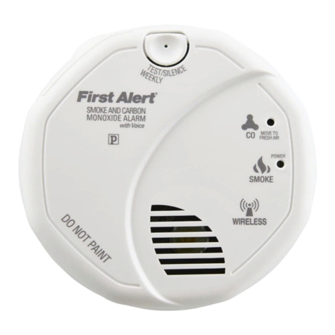
First Alert ONELINK SCO501B2 user manual
unii
unii UN-WSM RND installation instructions
System Sensor
System Sensor B501 Installation and maintenance instructions
Ei Electronics
Ei Electronics EI 170 Instruction leaflet

Honeywell
Honeywell ADEMCO 5806 installation instructions
