Telguard TG-7 Series User manual
Telguard TG-7 Series
QUICK INSTALLATION GUIDE [BACKUP MODE]
Installation Summary
There are seven steps in installing Telguard properly. IF YOU DO NOT
PROCEED IN THE ORDER AND MANNER PRESCRIBED, YOU MAY
NOT COMPLETE THE INSTALLATION IN THE TIME ALLOCATED.
STEP 1: REGISTER FOR CELLULAR SERVICE
The registration form may be completed online through our 24/7 dealer portal
www.telguard.com.
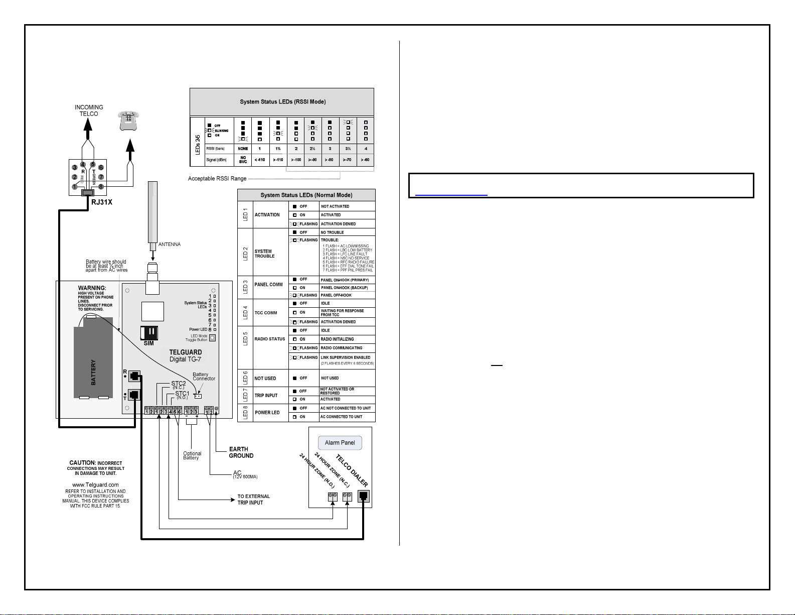
STEP 2: LOCATE UNIT AND MEASURE SIGNAL STRENGTH (RSSI)
With theunit powered up, press the LED/RSSI Mode Toggle button one time, LEDs will now
indicate signal strength. Minimum recommended is 2 (2 on solid). Position the Telguard in a
location where minimum signal strength is satisfied. Press the LED/RSSI Mode Toggle button a
second time to exit RSSI mode.
STEP 3: TRANSMIT PANEL ALARMS OVER THE TELCO CONNECTION
Verify the alarm panel is programmed properly by transmitting a signal over the telco connection.
This step is important to verify that the alarm panelis programmed with valid account code and
central station information before transmitting signals through the cellular network.
STEP 4: PROGRAM, ACTIVATE & TRANSMIT PANEL ALARMS OVER THE
CELLULAR RADIO NETWORK
Connect the alarm panel's digital dialer output to the Telguard and verify the alarm signals can be
reliably sent through Telguard over the cellular network to thecentral station digital receiver. The
incoming Telco line is not connected to Telguard during thisstep. A minimum of two alarm
signals must be transmitted. Activation is confirmed when LED 1 becomes illuminated.
(NOTE: THE FIRST ALARM WILL ACTIVATE THE UNIT AT THE TELGUARD COMMUNICATION
CENTER,IT WILL NOT GO TO THE CENTRAL STATION,ALL SIGNALS AFTER THE FIRST ARE
SENT TO THE CENTRAL STATION)
STEP 5: CONNECT SUPERVISORY TRIP OUTPUTS
Wire the Telguard's supervisory tripoutputs to the alarm panel and then test.
STEP 6: CONNECT TRIP INPUT (OPTIONAL)
Wire an external relay to the trip input lead and ground, andtest.
STEP 7: COMPLETE THE INSTALLATION
Attach earth ground to the Telguard, reconnect Telco, and permanently mount the unit.

56050102
24 HOUR ZONE (N.C.)
TELCODIALER
ANTENNA
T
R
www.Telguard.com
REFER TO INSTALLATION AND
OPERATING INSTRUCTIONS
MANUAL. THIS DEVICE COMPLIES
WITH FCC RULE PART 15.
SIM
CAUTION: INCORRECT
CONNECTIONS MAY RESULT
IN DAMAGE TO UNIT.
LED Mode
Toggle Button
4
LEDs 2-5
Signal (dBm) NO
SVC < -110 > -110 > -100 > -90 > -80 > -70 > -60
RSSI (bars) NONE 1½1 2 2½ 3 3½
System Status LEDs (RSSI Mode)
OFF
BLINKING
ON
OFF
BLINKING
ON
4
LEDs 2-5
Signal (dBm) NO
SVC < -110 > -110 > -100 > -90 > -80 > -70 > -60
RSSI (bars) NONE 1½1 2 2½ 3 3½
System Status LEDs (RSSI Mode)
OFF
BLINKING
ON
Alarm Panel
1 FLASH = AC LOW/MISSING
2 FLASH = LBC LOW BATTERY
3 FLASH = LFC
4 FLASH = NSC NO SERVICE
5 FLASH = RFC RADIO FAILURE
6 FLASH = DTF DIAL TONE FAIL
7 FLASH = PPF PNL PRES FAIL
LED 1
OFF NOT ACTIVATED
ACTIVATEDON
System Status LEDs (Normal Mode)
ACTIVATION DENIEDFLASHING
ACTIVATION
LED 2
OFF
FLASHING
SYSTEM
TROUBLE
NO TROUBLE
TROUBLE:
LED 3
OFF
ON
PANEL COMM PANEL ON-HOOK (PRIMARY)
PANEL ON-HOOK (BACKUP)
LED 4
OFF IDLE
WAITING FOR RESPONSE
FROM TCC
ON
ACTIVATION DENIEDFLASHING
TCC COMM
LED 5
OFF IDLE
RADIO INITIALIZINGON
RADIO COMMUNICATINGFLASHING
RADIO STATUS
Battery
Connector
Acceptable RSSI Range
Battery wire should
be at least ¼ inch
apart from AC wires
24 HOUR ZONE(N.O.)
WARNING:
HIGH VOLTAGE
PRESENT ON PHONE
LINES.
DISCONNECT PRIOR
TO SERVICING.
PANEL OFF-HOOKFLASHING
BATTERYBATTERY
LED 6LED 7LED 8
OFF NOT USED
NOT USED
TRIP INPUT
AC NOT CONNECTED TO UNIT
AC CONNECTED TO UNIT
OFF
ON
POWER LED
FLASHING 5-MIN. SUPERVISION ENABLED
(2 FLASHES EVERY 6 SECONDS)
Alarm Panel
TELCO DIALER 1
TELCOHOUSE
TELCO DIALER 2
TELCOHOUSE
TELCO DIALER 1
TELCOHOUSE
TELCO DIALER 2
TELCOHOUSE
T
R
TG-7FS
TIP
RING
TIP1
RING1
TIP
RING
TIP1
RING1
OPTIONAL CONNECTION:
(TWO TELCO CONNECTIONS FROM THE
ALARM PANEL SPLICED INTO THE TG-7FS)
TELGUARD
Digital TG-7
EARTH
GROUND
AC
(12V 800MA)
TO EXTERNAL
TRIP INPUT
STC2
(N.C.)
STC1
(N.O.)
123 5 6 1 2
111 222 111 3332224
Optional
Battery
++
-
NOT ACTIVATED OR
RESTORED
ACTIVATED
OFF
ON
1
2
3
4
5
6
7
8
Power LED
System Status
LEDs
1
2
3
4
5
6
7
8
Power LED
System Status
LEDs
Telguard TG-7 Series
QUICK INSTALLATION GUIDE [SOLE PATH]
Installation Summary
There are seven steps in installing Telguard properly. IF YOU DO NOT
PROCEED IN THE ORDER AND MANNER PRESCRIBED, YOU MAY NOT
COMPLETE THE INSTALLATION IN THE TIME ALLOCATED.
STEP 1: REGISTER FOR CELLULAR SERVICE
The registration form may be completed online through our 24/7 dealer portal
www.telguard.com.
STEP 2: LOCATE UNIT AND MEASURE SIGNAL STRENGTH (RSSI)
With the unit powered on, press the LED/RSSI Mode Toggle button one time, LEDs will now indicate
signal strength. Minimum recommended is 2 ½ (2 on solid and 1 flashing). Position theTelguard in a
location where minimum signal strength issatisfied. Press the LED/RSSI ModeToggle button a
second timeto exit RSSI mode.
STEP 3: CONFIGURE ALARM PANEL FOR SOLE PATH CONNECTION
Fire panels are typically provided with two Telco connections. Because the TG-7 provides a single
connection, the panelmust beset up accordingly. Thefirst method of installationis toconfigure the
panel to disable the second Telco connection. If this is not an option due to panel limitations, it is
possible to splice both TIP and RING connections from the panel into the single jack of the
Telguard. The TG-7 is capable of providing dialtone to both Telco connections.
STEP 4: ACTIVATE & TRANSMIT PANEL ALARMS OVER THE CELLULAR
RADIO NETWORK
Make sure to select Sole Path communicationfor your Telguard during the registration process.
LED 3 will be off when idle, if successful. Connect the alarm panel's digital dialer output to Telguard
and verify that alarm signals can be reliably sent through Telguard over cellular to the central
station digital receiver. A minimum of two alarm signals must be transmitted. Activation is
confirmed when LED 1 is illuminated.
(NOTE: THE FIRST ALARM WILL ACTIVATE THE UNIT AT THE TELGUARD COMMUNICATION
CENTER,IT WILL NOT GO TO THE CENTRAL STATION,ALL SIGNALS AFTER THE FIRST ARE
SENT TO THE CENTRAL STATION)
STEP 5: CONNECT SUPERVISORY TRIP OUTPUTS
Wire Telguard's supervisory trip outputs to the alarm panel and test.
STEP 6: CONNECT TRIP INPUT (OPTIONAL)
Wire an external relay input to the trip input lead and ground, andtest.
STEP 7: COMPLETE THE INSTALLATION
Attach earth ground to the Telguard, and permanently mount the unit.
Other manuals for TG-7 Series
5


