Oppermann Regelgeräte DRM 3.3 User manual

Ceiling smoke alarm DRM 3.3 – bus-enabled for STG 1.2
Fire Protection | Data sheet No. 40102 | Version 01-2011 | 1| 4
Technical Data
Power supply: 24 V DC nominal voltage
17 – 41 V DC from STG 1.2
via system ringbus
Power consumption:
Standby current: 460 µA (60 µA RMS+ 400 µA RM)
Alarm current: < 10 mA
Short-circuit current : < 10 mA
Rated continuous current: 1 A (RMS), 30 mA (RM)
LED displays:
Alarm: 2 red LEDs light up on RM 3.3
Short-circuit: yellow LED lights up on the side
of the RMS 3.3
Alarm + fault signals: via bus on STG 1.2
Rated
operating temperature: -10 °C – +50 °C
Rated
storage temperature: -30 °C – +60 °C
Rated humidity: 10 – 95% RH (at 40 °C)
Housing: ABS plastic
Dimensions: Ø 100 x 52 mm
Weight: approx. 0.1 kg
Installation: wall/ceiling installation
Protection type: IP 42
Colors: white RAL 9010 (WHT)
Connections: screw terminals max. 2.5 mm²
Certication: EN 54-7
VdS-certication: G208038
Labeling RM 3.3: ALK-E 0832-CPD-0611 & CE
Labeling RMS 3.3: YBO-R/SCI 0832-CPD-0963 & CE
• Operated with Oppermann control unit STG 1.2
• Up to 99 DRM 3.3 can be connected per STG 1.2
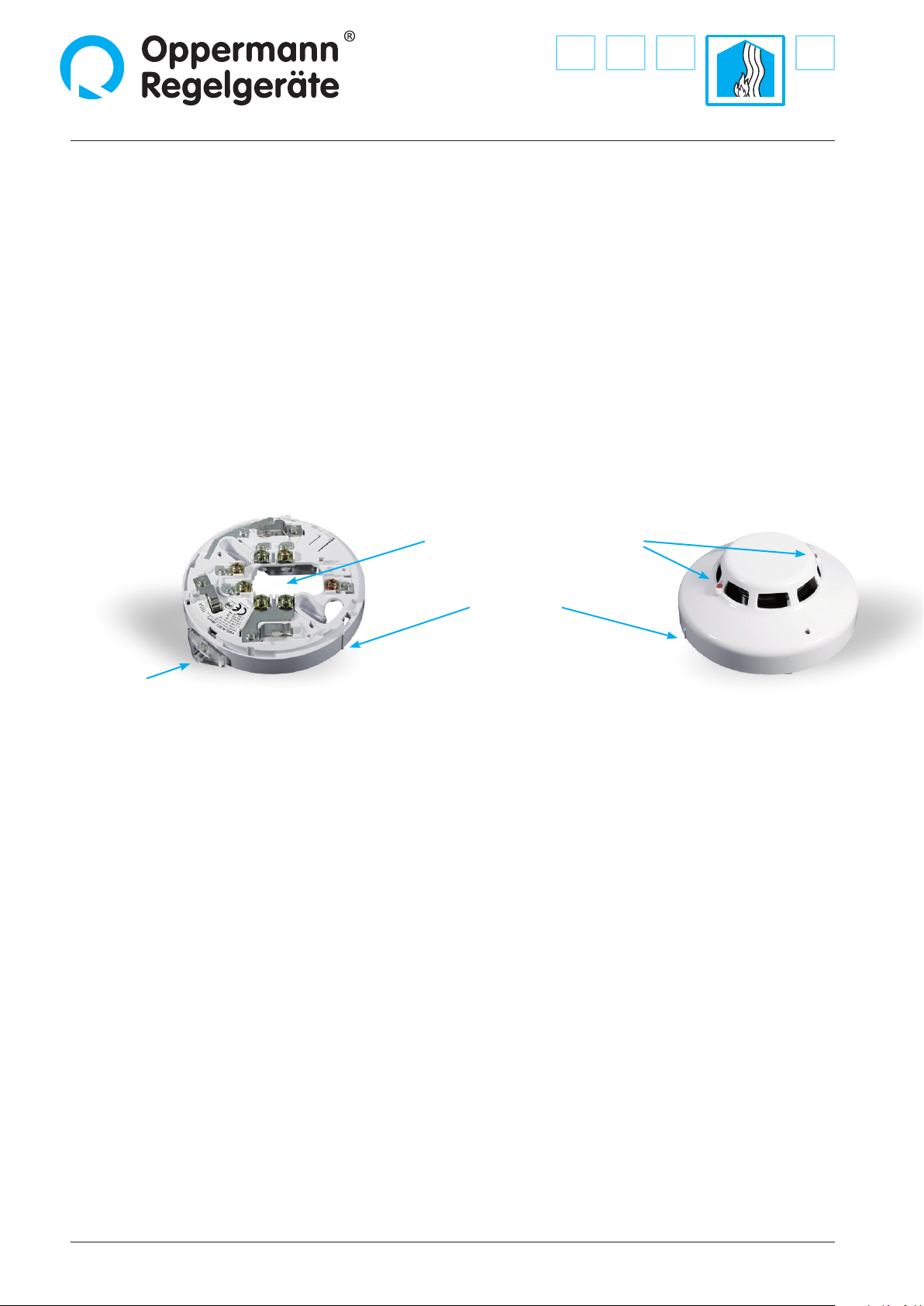
• The DRM 3.3 consists of smoke alarm RM 3.3
and smoke alarm socket RMS 3.3
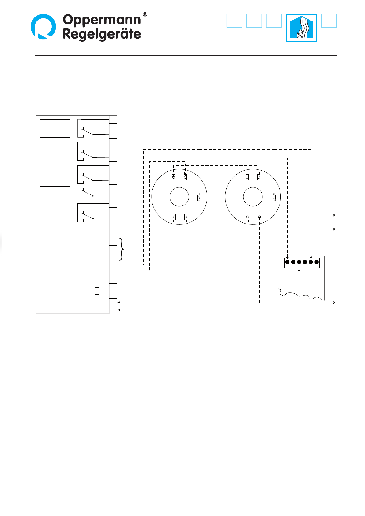
• Power supply and communication via safety
ringbus – monitored for short-circuit and
broken cable
• LED display on alarm (red – RM 3.3) and
short-circuit (yellow – RMS 3.3)
• Easy and convenient installation
Product description/functionality
The DRM communicates with the STG control unit via the safety-
monitored system ringbus. The alarms forward fault and alarm
messages to the STG and indicated on a display. A technician or
building manager can therefore see all connected alarms at a
glance. The system ringbus monitors for short-circuits and broken
cables. An alarm or fault message is indicated on the STG in each
case. Messages must be manually reset on the STG after the fault
has been lifted (not self-canceling).
The optical alarm (scattered light eect) provides early warning
for incipient res with smoke, in particular smoldering res. The
sensor cavity houses a dual infrared light source with 360° detec-
tion. Normally, the pulsating light ray from the transmitter does
not reach the receiver. If smoke particles enter the sensor cavity,
a portion of the light is reected to the receiver resulting in an
alarm trigger. Two red LEDs on the RM 3.3 smoke alarm and one
red LED on the STG 1.2 indicate an alarm.
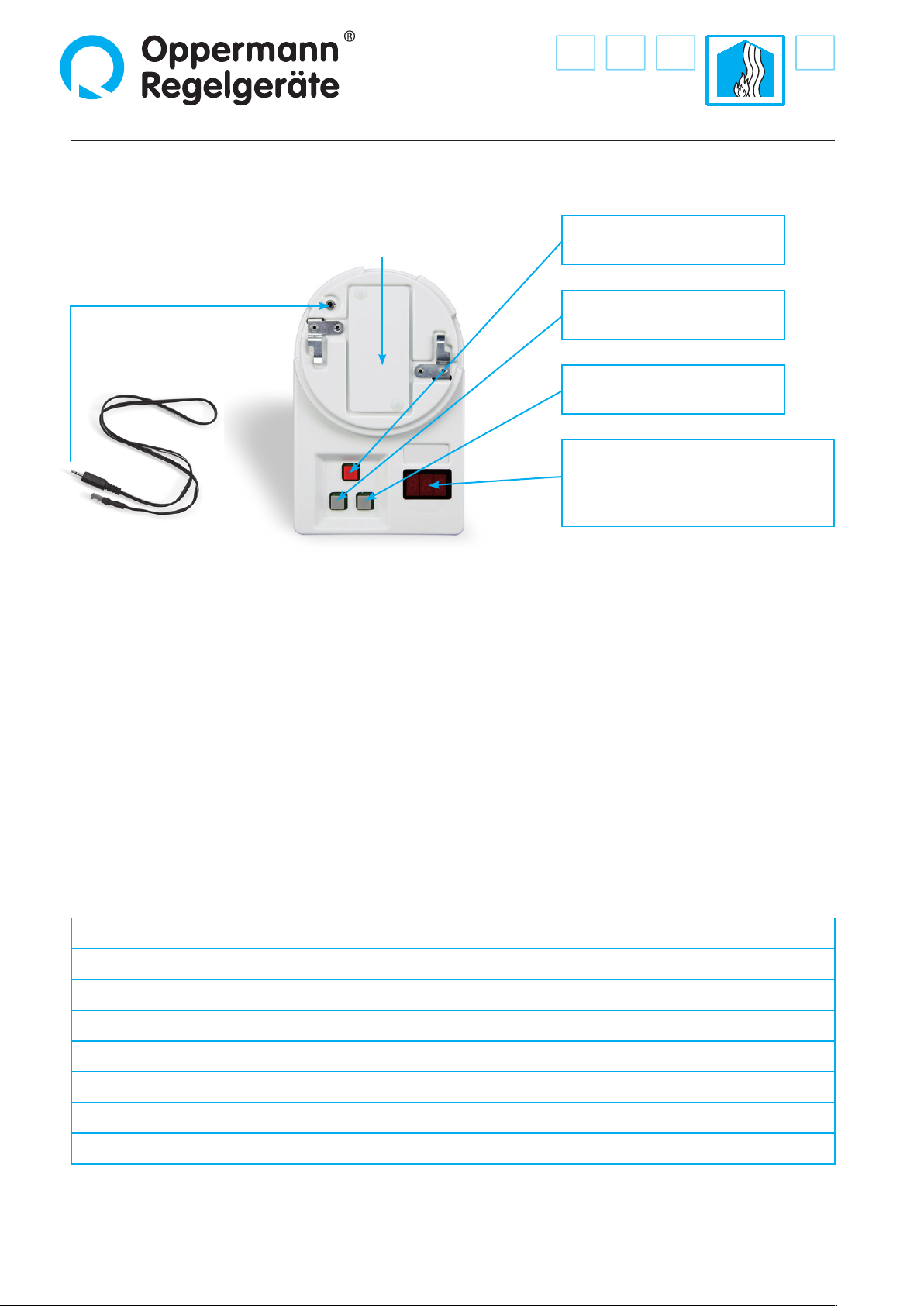
The alarm status on the RM 3.3 smoke alarm expires automati-
cally after the alarm cavity is free (LEDs on RM go dark). The alarm
remains intact on the STG until it is manually reset at the control
unit. The STG can only be reset when the alarm LEDs in the smoke
alarm have gone dark.
Starting at a contamination level of 70 %, the STG 1.2 indicates
a message to prompt targeted maintenance. An alarm is issued
starting at 99% contamination.
Important note: Please also note separate specication sheets
for STG 1.2.

Ceiling smoke alarm DRM 3.3
2| 4| Fire Protection | Data sheet No. 40102 | Version 01-2011
Installation
All work must only be performed by suciently qualied trades-
men. The respectively applicable local rules and regulations (e.g.
national building codes, electrical/VDE regulations, etc.) must be
observed. Installers and operating entities are required to su-
ciently familiarize themselves before startup. We are not liable
for printing errors and changes after printing. Appropriate use
implies compliance with operating and installation instructions.
We are not liable for losses due to inappropriate use. Unautho-
rized or inappropriate manipulations or modications of the
device render the operating permit, the product warranty and
warranty claims null and void.
Startup and maintenance/test
The alarm must be tested after installation and at least once
annually with suitable test spray (e.g. Oppermann RDP 300). The
red LED on the smoke alarm must indicate; the control unit must
switch to„Alarm“ and lock out. The unit is unlocked with the reset
button provided the smoke alarm cavity is free.
The ceiling smoke alarm consists of the smoke alarm socket RMS
3.3 and the smoke alarm RM 3.3. The alarm is mounted to the
socket with a bayonet lock and facilitates straightforward opera-
tion of the alarm. The smoke alarm RM 3.3 is engaged to the socket
in clockwise direction. Note the lateral mark for this purpose. Align
the smoke alarm approximately 15° before the socket mark and
then rotate in clockwise direction. The smoke alarm is disengaged
in counter-clockwise direction. We recommend gripping the socket
rmly and taking care to avoid misalignment between the two
parts. The socket is installed in an appropriate location with dowels
and screws.The cable is routed through the center.
Yellow short-
circuit LED
Red alarm LEDsCable opening
Marking
for bayonet lock
closed: marks in alignment
Rotate RM 3.3 in counter-clockwise direction to open
Smoke alarm RM 3.3Smoke alarm socket RMS 3.3

Fire Protection | Data sheet No. 40102 | Version 01-2011 | 3| 4
Ceiling smoke alarm DRM 3.3
Electrical connection on STG 1.2 control unit
All work on electrical installations or equipment must only be performed in accordance with electrical engineering principles by a
trained electrician or by an instructed person under the direction and supervision of a trained electrician.
Contamination
Service
Malfunction
Alarm
GLT bus A
1
2
3
4
5
6
7
8
9
10
11
12
13
14
15
16
17
18
19
20
21
22
23
24
25
26
B
A
B
GND 485
GND smoke alarm
Smoke alarm bus
Modbus
RTU to
the BMS
Shield
Power supply for STG Manual call point DKM 3.3
Ceiling smoke detector
DRM 3.3
Loop +IN
Loop +
GND
inin
in in
out
outout
out
GND
Loop +
Loop –
Loop –
Loop –IN
Loop +OUT
Loop –OUT
Screen IN
Screen OUT
24 V AC/DC
24 V AC/DC
Shield
1 2
5
7
6
1 2
5
7
6
Contacts are shown disconnected from power (alarm)
Alarms are supplied with power from the system ringbus. The bus cable must be shielded on both sides (terminal 7).
The maximum bus length is 250 m (loop length 500 m).
Smoke alarm address
Each connected alarm must be assigned a dedicated, unique BUS address between 1 and 99. This is accomplished with the PG 3.3
programming tool (accessory) The standard default address is 127 and is therefore not recognized by the STG. On request, Opper-
mann can congure the alarms with custom BUS addresses (indicate in your order - particularly important when ordering replace-
ment parts). A fault alarm is triggered if the same alarm address is assigned twice on the ringbus. If the alarm message is changed,
the alarm must be reregistered with the STG in service mode. The positioning of addressed DKMs in the ringbus is arbitrary.

4| 4| Fire Protection | Data sheet No. 40102 | Version 01-2011 Specications subject to change.
Ceiling smoke alarm DRM 3.3
Oppermann Regelgeräte GmbH | Im Spitzhau 1 | 70771 Leinfelden-Echterdingen, Germany
Phone +49 711 72723560 | Fax +49 711 7280527 | info@oppermann-regelgeraete.de |www.oppermann-regelgeraete.de
Programming with PG 3.3 programming tool
Interface for coaxial
programming connector
Battery compartment
9 V battery
• Store address
• Read analog value (for information)
• Switch on
• Adjust address in increments of 10
• Switch o
• Adjust address in increments of 1
• Bus address display
(1 – 127 possible, set 1 – 99 for STG)
• Fault indicator/analog value display
(only on DRM)
The coaxial cable is only needed for push button alarm DKM 3.3
Programming is only possible when the alarm is disconnected from power. Programming is not possible if the loop is connected
to power. Programming is also not possible during an alarm. Reset the alarm rst.
Programming:
• Disconnect smoke alarm RM 3.3 from smoke alarm socket.
• Engage smoke alarm RM 3.3 onto the bayonet lock of the programming tool (rotate in clockwise direction). Align exterior mark on
smoke alarm RM 3.3 approx. at 8 o‘clock position on the programming tool and then rotate approx. 15° in clockwise direction.
• Switch on programming tool by pressing the left gray button. The address is read from the alarm and shown in the display.
• Change address with the two gray buttons. Dots blink behind the gures while the address is being changed.
• Save address with the red button. The blinking dots behind the gures vanish.
• Disengage alarm in counter-clockwise direction and switch o programming tool.
• Note smoke alarm address on a sticker of your choice and attach to smoke alarm.
Potential fault alarm on programming tool:
bAt Replace battery (battery service life: approx. 3,000 programming cycles)
E0 Incorrect programming attempt (Address > 127)
E1 DRM/DKM alarm not found
E2 Alarm not operational
E3 Incorrect sensor reply
E4 No alarm found
E5 Read error
E6 Error while reading analog value (only DRM)
Other Oppermann Regelgeräte Smoke Alarm manuals