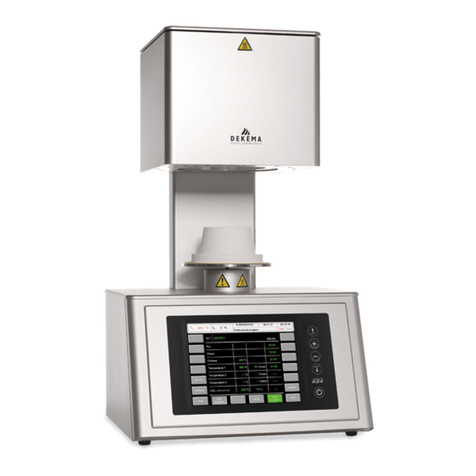
Dekema Austromat D4 User manual

0INTRODUCTION.............................................................................................................................. 3
1COMPONENTS................................................................................................................................3
2TECNICAL SPECIFICATIONS........................................................................................................ 4
2.1 CERAMIC FURNACE UNIT.............................................................................................................. 4
2.2 VACUUM PUMP UNIT..................................................................................................................... 4
3DESCRIPTION OF THE EQUIPMENT............................................................................................ 5
3.1 FRONT........................................................................................................................................ 5
3.2 BACK.......................................................................................................................................... 6
4SAFETY MEASURES...................................................................................................................... 7
4.1 NOTES REGARDING SAFETY ........................................................................................................ 7
4.2 SETUP ........................................................................................................................................ 8
4.3 OPERATION................................................................................................................................. 8
5STARTUP ...................................................................................................................................... 11
5.1 SETUP ...................................................................................................................................... 11
5.2 INSTALLATION ASSISTANT........................................................................................................... 11
6MAINTENANCE AND SERVICE................................................................................................... 12
6.1 MAINTENANCE........................................................................................................................... 12
6.2 TEMPERATURE CALIBRATION ..................................................................................................... 12
6.3 CHECK-PROGRAM..................................................................................................................... 13
6.4 CHANGING THE BATTERY ........................................................................................................... 14
6.5 REPLACING THE HEATING ELEMENT ............................................................................................ 15
6.6 SERVICE AND TRANSPORT......................................................................................................... 15
6.7 REPLACEMENT PARTS................................................................................................................ 15
7USER INTERFACE........................................................................................................................ 16
7.1 FIRST STEPS............................................................................................................................. 16
7.1.1 CONTROLS ........................................................................................................................ 17
7.1.2 SET PROGRAMS (OPTIONAL)............................................................................................... 19
7.1.3 INDIVIDUAL FIRING PROGRAMS ............................................................................................ 21
7.2 PROGRAM MANAGER................................................................................................................. 23
7.3 PROGRAM DISPLAY.................................................................................................................... 24
7.4 PROGRAM PROCEDURE.............................................................................................................. 26
7.5 PROGRAM EDITOR ..................................................................................................................... 29
7.5.1 INDIVIDUAL PROGRAMS – STANDARD .................................................................................. 30
7.5.2 INDIVIDUAL PROGRAMS – PROFESSIONAL............................................................................ 31
7.5.3 INDIVIDUAL PROGRAMS – PRESS PROGRAMS (ONLY D4PRESS).......................................... 31
7.5.4 SET PROGRAMS................................................................................................................ 32
7.5.5 EDITING WHILE THE PROGRAM IS RUNNING........................................................................... 32
7.6 THE SETUP MENU..................................................................................................................... 32
7.6.1 FURNACE SETTINGS........................................................................................................... 33
7.6.2 MAINTENANCE PROGRAMS ................................................................................................. 34
7.6.3 DATA RECORDING AND TRANSFER....................................................................................... 36
7.6.4 ADDITIONAL FUNCTIONS..................................................................................................... 37
8PRINTING RECORDS AND CONNECTING TO A PC ................................................................. 39
8.1 PRINTING RECORDS .................................................................................................................. 39
8.2 PC CONNECTION (DREAM®).................................................................................................... 41
9PRACTICAL TIPS.......................................................................................................................... 42
10 INDEX............................................................................................................................................. 44
DEKEMA Dental-Keramiköfen GmbH, AUSTROMAT®D4, Version 3, 2006

0 Introduction 3
0 INTRODUCTION
Dear Customer,
Congratulations on your new AUSTROMAT D4 ceramic furnace. DEKEMA’s
many years of experience in the field of dental furnace construction have gone into
this equipment ensuring a very high level of quality, and exceptional performance
and reliability. In order to take full advantage of the possibilities your ceramic
furnace offers to obtain superior results, we would like to ask you to spend a little
time studying these instructions. The technical specifications and a description of
the furnace can be found in Sections 2 and 3. In order to ensure reliable, long-
lasting operation of the ceramic furnace, please observe the safety measures
indicated in Sections 4 and 5 and the suggestions regarding service and
maintenance of the furnace in Section 6. The AUSTROMAT D4 is a menu-
operated furnace whose functions are controlled via keyboard input and screen
readouts. The control menus are described in Section 7 from the initial steps to the
device’s setup settings. Practical examples help clarify the explanations. Section 8
covers making records and the link to the computer. Section 9, Practical Tips, is to
assist you in troubleshooting. References in the text refer to this section. Finally, the
index enables you to quickly find specific functions or commands.
Please note the following warning symbols:
This symbol warns of hazardous electrical voltage where there is a danger to life
and limb. Note these instructions on the device, and be especially careful.
This symbol indicates a burning hazard from hot surfaces. Note these instructions
on the device, and be especially careful.
This symbol indicates a personal hazard to life and limb. Take note of this warning
in the operating instructions, and take extra precautions.
1 COMPONENTS
• AUSTROMAT D4 ceramic furnace with power cable
• Software module
• Vacuum pump (diaphragm pump) with electrical power supply cable and
vacuum line (silicone tube)
• Firing table and press table (only D4press)
• Furnace tweezers
• Operating instructions
• Packaging material
• Calibration set for calibrating the temperature
Ensure that all components have been supplied, and that the equipment has not
suffered any visible damage in transport. If this is not the case, please immediately
contact your service partner. Please store the packaging (two cardboard boxes and
foam for protecting against jolts during transportation) in case you need to ship the
equipment at a later date.
DEKEMA Dental-Keramiköfen GmbH, AUSTROMAT®D4, Version 3, 2006

2 Tecnical Specifications 4
2 TECNICAL SPECIFICATIONS
2.1 CERAMIC FURNACE UNIT
Supply voltage depending on the type (rating plate on the rear):
~ 230 V 220…240 VAC / 50 – 60 Hz
~ 115 V 110…120 VAC / 50 – 60 Hz
~ 100 V 95…105 VAC / 50 – 60 Hz
Power consumption maximum 1450 W with pump
Fuses according to type
~ 230 V 2 x 6,3 A T 250 V
~ 115 V 2 x 16 A T 500 V
~ 100 V 2 x 16 A T 500 V
Battery Lithium-cell 3,6 V / 2000 mAh
Vacuum pump connection
socket according to type
Interfaces serial (with the PC) or printer
Soft or memory module (same construction)
Max. firing temperature 1,200°C
Max. rate of temperature rise 160°C/min from 20°C to 500°C
120°C/min from 500°C to 1000°C
60°C/min from 1,000°C to 1,200°C
Dimensions 35 x 63 x 28 cm (W x H x D, D4)
35 x 74 x 28 cm (W x H x D, D4press)
Weight 18.0 kg (D4)
18.5 kg (D4press)
2.2 VACUUM PUMP UNIT
Pump type Service-free diaphragm pump
Supply voltage depending on the type
(pump rating plate on the rear):
~ 230 V 220…240 VAC / 50 – 60 Hz
~ 115 V 110…120 VAC / 50 – 60 Hz
~ 100 V 95…105 VAC / 50 – 60 Hz
Ultimate pressure < 30 hPa
Weight 6 kg
DEKEMA assumes no liability for damage arising from the use of a different vacuum
pump than the one supplied.
DEKEMA Dental-Keramiköfen GmbH, AUSTROMAT®D4, Version 3, 2006

3 Description of the Equipment 5
DEKEMA Dental-Keramiköfen GmbH, AUSTROMAT®D4, Version 3, 2006
3 DESCRIPTION OF THE EQUIPMENT
3.1 FRONT
Fig. 1 and 2 are schematic illustrations of the front and rear of the
AUSTROMAT D4.
Figure 1
Front view AUSTROMAT D4
The top of the furnace contains the firing chamber. The bottom section of the
furnace contains the electronic and mechanical furnace components used to move
the lift system comprising the lift rod, lift seat with sealing ring (yellow O-ring), and
the firing table on which the objects to be fired are placed. On the cover plate, there
is a cylindrical height gauge that corresponds with the free height of the firing
chamber.
On the front of the bottom part of the furnace, you will find the following controls:
screen, function keys (softkeys), alphanumeric keypad, control keys, and an LED to
display when the device is ready to be used.
top section of
furnace with
firing chamber
back column
bottom section of
furnace with
electronic and
mechanical
components
LED
ON / OFF
height gauge
firing object
lift rod
lift seat with
sealing ring
firing table
Display
CREAMA
T
lid
keypad
ON

3 Description of the Equipment 6
DEKEMA Dental-Keramiköfen GmbH, AUSTROMAT®D4, Version 3, 2006
3.2 BACK
Figure 2
Back of the AUSTROMAT D4
On the back of the bottom section of the furnace you will find the main ON/OFF
switch, the battery compartment, a label with the production number, the fuses, and
the fixed power cable.
The following connections exist: one plug connection with two clips to hold the soft
or memory module, a serial interface for a PC connection (top socket connector) the
socket connector for the vacuum pump power cable, and a connection for the
vacuum line.
top section of
furnace with
firing chamber
back column
bottom section of furnace
with electronic and
mechanical components
mains cable
connection vacuum pump vacuum tube
serial interfaces
fuse
battery
com
p
artment
ON / OFF
switch
production
number
software /
memory module
cover plate

4 Safety Measures 7
4 SAFETY MEASURES
4.1 NOTES REGARDING SAFETY
• Never operate the furnace without the firing table!
• Always use the firing table or press table that is required for proper use
• Familiarize yourself with the safety steps and operating instructions to prevent
damage to humans and/or materials.
• The AUSTROMAT D4 was designed for firing dental ceramic objects.
We assume no liability or guarantee when the device is improperly used
handled or not used according to instructions.
• In particular, materials may not be heated that may trigger explosions,
implosions and hazardous or flammable gases.
• The equipment may only be operated with the indicated supply voltage (the
rating plate is on the back). Please use only suitable power sockets with
ground contacts, and never use adapter plugs.
• The power socket should be close to the device and easily accessible. In an
emergency, unplug the power plug and turn off the furnace (the main switch is
on the back, see p. 6, Figure 2).
• When you mount the object to be fired and firing tray, make sure that nothing
extends over the edge of the firing table. The object to be fired and the heat
insulation material may otherwise be damaged when you close the furnace.
• Only use fuses with the indicated lag and nominal current (see p. 4 Tecnical
Specifications).
• Acute danger of burning (only the D4press): If the lift is moved down after
running a press program, visually check if the press muffle is on the firing table.
Move the lift down to a safe lift posiiton (see the setup menu: “Safe lift
position“, section 7.6.1). If the press muffle is not lying on the firing table, close
the lift and let the press muffle cool some more.
• Do not use your hands or any objects for grasping things in the firing chamber.
This can cause injury from burns or electrical shock.
• Never directly contact hot parts of the furnace. Do not grasp the lift seat, firing
table or object to be fired with your bare hands. Never put your hand into the
hot firing chamber.
• Protect yourself from electric shock. Do not simultaneously touch any
hazardous active parts such as an optional core-guided heating element and
parts connected to the protective conductor. Protect yourself, for example by
using insulated tools and/or clothing.
DEKEMA Dental-Keramiköfen GmbH, AUSTROMAT®D4, Version 3, 2006

4 Safety Measures 8
• Before the top and bottom are opened, the furnace must be disconnected from
the power source (turn off the furnace and pull the plug). The main switch is on
the back (see p. 6, Figure 2.)
• If a lightening stroke hazard exists, separate the furnace from the power source
(turn it off and pull the plug).
• If the furnace cannot be operated safely, pull the power plug, and make sure
that the furnace cannot be unintentionally switched on, especially when the
following error message appears: TEMPERATURE LIMIT EXCEEDED.
SWITCH FURNACE OFF IMMEDIATELY!
• If the ground conductor is interrupted either inside or outside the device, or the
ground conductor is released, the furnace is hazardous to operate. The
connection may never be intentionally severed.
• Further reasons for assuming that the equipment cannot be used safely:
Visible damage to the housing or power cable, malfunctioning, frequent need
to exchange fuses, long storage in a bad environment (moisture). Please also
follow the setup instructions in Section 4.2.
• Note that the furnace requires several hours to cool after it is turned off.
• Do not run the connection lines past hot locations of the furnace, and
especially avoid direct contact.
4.2 SETUP
• Set up the furnace in a suitable place on a dry, flat, solid surface.
• Make sure that flammable materials or objects that can be damaged by heat
are sufficiently distance from the furnace.
• Never place such materials or objects on the pot cover and the cover plate.
• The vents in the top section must not be obstructed in order to ensure
circulation of cooling air.
• The vacuum pump should be set up in dust-free, well-ventilated area. Please
also note that the length of the vacuum hose is approx. 1.5 m from the pump to
the furnace. Never block the vents of the pump. Do not store easily
combustible or flammable materials close to the pump.
4.3 OPERATION
• Never operate the ceramic furnace without supervision.
• When positioning the firing object and firing tray, ensure that no parts jut out
over the edge of the firing table. There is a danger of damaging the firing object
and thermal insulation material when closing the furnace.
DEKEMA Dental-Keramiköfen GmbH, AUSTROMAT®D4, Version 3, 2006

4 Safety Measures 9
• Never directly contact hot parts of the furnace. Do not grasp the lift seat, firing
table or firing object with your bare hands. Never put your hand into the hot
firing chamber.
• Protect yourself from electric shock. Do not simultaneously touch any hazardous
active parts such as an optional core-guided heating element and parts
connected to the protective conductor. Protect yourself, for example by using
insulated tools and/or clothing.
• Note that the furnace automatically heats up approximately 30 seconds after it
is turned on, even when the firing chamber is open.
• After a program memory is selected or the program is aborted, the standby
temperature of the selected or aborted program is automatically set in the firing
chamber after approximately 20 seconds. This can be the preheating
temperature or the firing chamber temperature required for drying.
• Do not use your hands or any objects to grasp things in the firing chamber.
This can cause injury from burns or electrical shock.
• The firing chamber has a clear height of 36 mm. The fired objects (including
the firing tray) may not exceed this height since the temperature sensor could
otherwise be damaged. On the cover plate, there is a cylindrical height gauge
that corresponds with the free height of the firing chamber.
Figure 3
Height gauge 36 mm
= max. height
• In the Press mode of the D4press, conventional cylindrical press muffles with a
press plunger can be used whose maximum height is 70 mm without the press
plunger, and 90 mm with the press plunger, and whose diameter is not greater
than 60 mm without the press plunger.
• While the firing program is running, the lift automatically moves up and down.
Make sure that no objects are in the way that could hinder the lift movement.
Also do not attempt to manually stop or accelerate the lift.
• The furnace should not be operated for some time after sudden change of
ambient temperature as otherwise condensation may occur in the electronic
components, thus causing damage.
• Never operate the furnace without the firing table!
DEKEMA Dental-Keramiköfen GmbH, AUSTROMAT®D4, Version 3, 2006

4 Safety Measures 10
If technical servicing or repairs are necessary, they should only be performed by
authorized professionals.
After repair work, the furnace must undergo a safety check:
Federal Republic of Germany VDE 0701
International according to the respective national guidelines
DEKEMA Dental-Keramiköfen GmbH, AUSTROMAT®D4, Version 3, 2006

5 Startup 11
DEKEMA Dental-Keramiköfen GmbH, AUSTROMAT®D4, Version 3, 2006
5 STARTUP
5.1 SETUP
First, please ensure that the package contains all parts indicated in the list of
components (Section 1) and keep the packaging material for any later transport.
Read the operating instructions before turning on the device. In particular,
familiarize yourself with the furnace description in Section 3, and read the safety
instructions in Section 4. Before starting the furnace, remove the software module
on the back by slightly pressing together the clips on the narrow side and pulling of
the module. Store it in a safe location (see Section 7.6 and Figure 22).
Step 1 Remove the software module on the back, and store it in a safe place
(see section 7.6 and Figure 22).
Step 2 Plug in the power cable into a power socket with a ground contact.
The ON/OFF switch is on the back of the furnace.
Step 3 Make sure that the pump connected loads (rating plate) correspond to
the furnace voltage supply values.
Step 4 Connect the vacuum pump: Plug in the vacuum pump power cable
into the associated connection socket of the AUSTROMAT D4
making sure that the guide groove is aligned. Screw tight the cable in
the socket since a bad electrical contact can damage the furnace.
Step 5 Connect the pump vacuum line (silicon tube) to the vacuum
connector on the back of the furnace.
Step 6 Turn on the furnace. The furnace performs an internal software and
hardware check and the lift moves down automatically. If necessary,
remove any ceramic dust from the lift seat and the sealing ring. Brush
the dust into a receptacle. Do not blow away the dust, and do not
inhale it.
Step 7 After it is turned on, the furnace waits approximately 30 seconds and
automatically heats up to the starting temperature of the preheating
program or the program that has been set.
TIP A
see p. 42
5.2 INSTALLATION ASSISTANT
The installation assistant is optionally activated at the plant before delivery. It is only
for special countries and customers. The installation assistant asks you to set up
the firing table and connect the pump. After pressing the NEXT key, an installation
routine runs. The firing chamber is dried, and the furnace is checked. The
installation routine takes approximately 45 minutes, and can be terminated at any
time with the CANCEL key. The installation assistant is started each time the
furnace is turned on until the entire installation routine has run once.

6 Maintenance and Service 12
6 MAINTENANCE AND SERVICE
6.1 MAINTENANCE
• Clean the housing, control panel and control elements with a soft cloth
moistened with a mild cleanser. Do not use scouring agents, scouring pads or
solvents such as alcohol, gasoline or acetone.
• Never contact the screen surface with sharp, rough or pointed objects such as
tweezers or ballpoint pens. These objects can scratch the screen surface.
• Always keep the sealing ring of the lift seat free of dust to ensure a reliable
vacuum. Use a brush with a receptacle (for ceramic dust), or a moist cloth.
• Every now and then, clean the lift rod with a dry cloth. Never oil or grease.
6.2 TEMPERATURE CALIBRATION
A number of factors influence the temperature of the firing object. These can
include: The color and shape of the firing tray, or the number and type of firing
objects. Other major influences can be age-related effects such as heating element
wear and changes to the thermoelectric properties of the temperature sensor. To
compensate for these factors and ensure normal firing results, we recommend that
you calibrate the furnace when the firing results change, or at least once a year.
Calibration is carried out by means of the calibration factor (CCF). Observe the
following instructions:
TIP F
see p. 43
• For new furnaces, we recommend that you calibrate the temperature for the
first time after approximately six months.
• An internal monitoring program notifies you when you should calibrate the
furnace temperature.
TIP C
see p. 42 • Make sure that the heating element and thermocouple are not damaged.
• Only use the DEKEMA calibration set that is for the specific furnace. This
consists of a curved silver wire and a white ceramic firing tray.
• For calibration, always use the firing table and not the press table (only applies
to the D4press)
• Make sure that the temperatures of all the firing programs are adjusted when
the CCF value changes. The firing temperatures of individual programs may
have to be corrected.
Calibrating the temperature with the calibration set:
The furnace must be thoroughly preheated before calibrating. The thermocouple
must be preconditioned. A cleaning firing must therefore precede temperature
calibration. Start the “Cleaning firing” program by selecting “Cleaning firing” in the
Setup menu, and press Program Start (Section 7.6.2).
Shove the curved silver wire from the calibration set (as shown in Fig. 4) in the
middle of the firing tray, then place it on the firing table.
DEKEMA Dental-Keramiköfen GmbH, AUSTROMAT®D4, Version 3, 2006

6 Maintenance and Service 13
Figure 4
Evaluating the silver wire
Start the Temperature calibration program by selecting “Temperature calibration” in
the Setup menu, and press Program Start (Section 7.6.2).
Fig. 4 illustrates how to evaluate the silver wire test specimen. Approach the correct
setting of the CCF in small steps of approximately two to three points (such as
1,004 auf 1,006). By increasing the CCF, you increase the firing temperature. By
reducing the CCF, you lower the firing temperature.
Observe the following procedure to change the CCF: Select "Temperature
calibration” in the Setup menu, and enter a new calibration factor (Section 7.6.2).
Minor corrections can be made instinctively. If there are very large or sudden
deviations from the original CCF, check for technical faults.
position of the specimen on the halved
DUCERA -
Tray, seen from above
ca. 25 mm
silver wire
15 mm
Silver specimen silver specimen is stuck in the
DUCERA -Tray
effective temperature too low
ra
ise CCF -value (c. 5 points) effective temperature o. k. effective temperature slightly too high
lower CCF -value (c. 3 points) effective temperature too high
lower CCF -
value (c. 5 points)
6.3 CHECK-PROGRAM
The AUSTROMAT D4 has an internal program that checks the function of
the major components (check program). Regularly using this non-editable program
makes it easier for you and the responsible service personnel to identify aged
components (such as heating element wear) and troubleshoot malfunctions (such
as vacuum leakage). After approximately 2000 firings, the device displays a
recommendation on the screen to start the self check program (duration: approx. 45
min). In the Setup menu, select the “Check program” function, and start the
program.
Start the check program only after running several firing programs, or after a
cleaning firing so that the oven is warmed up.
The results of the self-check are saved in a diagnosis file. In certain cases, the
AUSTROMAT D4 automatically notifies you upon starting a firing program if
diagnostic data indicate that a firing program will not run properly. This is the case
for example when the heating element is too old, and you want to reach a firing
temperature quickly.
DEKEMA Dental-Keramiköfen GmbH, AUSTROMAT®D4, Version 3, 2006

6 Maintenance and Service 14
Overview of error messages after the check program:
Error message Solution
1. “NO ERRORS FOUND” No errors were found.
2. “VACUUM PUMP DEFECTIVE” Contact your service partner (see p. 15).
3. “VACUUM SYSTEM LEAKY” Clean the lift seat and sealing ring while
observing safety instructions. Then rerun
the check program.
4. “SOLENOID VALVE LEAKY” Contact your service partner (see p. 15)
5. “CHANGE HEATING ELEMENT” Contact your service partner (see p. 15)
The error message "CHANGE HEATING ELEMENT" can also arise when the
heating element is technically functional. However, the check program requires a
nominal power supply to operate. When the effective power supply is below the
nominal value, the error diagnosis of the heating element can be incorrect. This
problem generally only occurs in Asian countries. Consult your local power
company.
6.4 CHANGING THE BATTERY
The firing programs and the software of the AUSTROMAT D4 are saved in
electronic memory modules that require an uninterrupted power supply to maintain
their memory function. When the furnace is turned off, this in ensured by a battery
(lithium cell 3.6 V / 2000 mAh, non-chargeable) that lasts approximately three years.
After a maximum of three years, the battery should be replaced for the memory
modules to work properly and to avoid loss of your firing programs. When turned on,
the furnace indicates the battery charge (Figure 7): 100% means the battery is new,
and approximately 10% means that the battery is an average of 2½ years old. Note
that this value is reached much earlier when the furnace is always turned off. At a
charge of 10%, the screen automatically displays a message that they battery must
be changed. Observe the following procedure:
• Order a new battery module (original replacement part, order No. LNE18082)
• Turn the furnace on, and leave it on while the battery is being changed.
• Open the battery compartment on the back of the furnace (two Phillips head
screws; see Figure 2).
• Carefully pull off the battery compartment cover with the battery and twisted
cable up to the cable plug. Unplug the cable.
• Insert the new unit comprising the battery compartment cover, battery and plug
(lithium cell / 3.6 V / 2000 mAh). The plug is protected against polarity reversal.
• Screw closed the battery compartment cover.
• Instruct the software that a new battery has been installed by selecting
“Change battery” in the Setup menu, and confirming that the battery has been
changed (Section 7.6.2).
DEKEMA Dental-Keramiköfen GmbH, AUSTROMAT®D4, Version 3, 2006

6 Maintenance and Service 15
Do not inform the software that the battery has been changed no new battery was
installed. Otherwise this can lead to lose the saved firing programs and software.
Do not throw away used batteries, but dispose of them as prescribed by law.
6.5 REPLACING THE HEATING ELEMENT
Over time, the heating element wears out from use. This can have a negative
influence on your firing results. For this reason, change the heating element at the
proper time. If the self-check program is run regularly (Section 7.6.2) a
recommendation will be displayed when the heating element wear has exceeded
the permissible limit. Follow the accompanying installation and safety instructions in
Section 4 to install the replacement heating element.
Only authorized personnel may perform technical work. (see p. 15)
TIP B
see p. 42
6.6 SERVICE AND TRANSPORT
We recommend regular maintenance of the equipment by your service partner. This
will ensure superior firing results.
If you need to replace wearing parts or want to update the set programs, please
consult the responsible service partner. If more extensive repairs to the furnace or
pump are required, please also contact your service partner. Please direct any
questions for the manufacturer to the following address:
DEKEMA Dental-Keramiköfen GmbH
Industriestraße 22
D-83395 Freilassing
Phone +49-(0) 86 54 / 46 39-0
Fax +49-(0) 86 54 / 6 61 95
Homepage http://www.dekema.com
When transporting the furnace and/or the pump, please use the original cardboard
box and packaging.
Please proceed as follows when packing the equipment,:
• Note that the device needs several hours to cool down (see p. 8).
• Close the firing chamber.
• Turn off the device and pull the pump plug.
• Only use the original box and the supplied packaging material.
6.7 REPLACEMENT PARTS
Only use original DEKEMA parts for servicing and maintaining the oven. Contact
your service partner, or contact DEKEMA directly.
DEKEMA Dental-Keramiköfen GmbH, AUSTROMAT®D4, Version 3, 2006

7 User Interface 16
7 USER INTERFACE
This and the following chapters inform you how to use the AUSTROMAT D4.
The menu control system is designed to display warnings or messages on the screen
when you do something wrong or make incorrect entries. If you have experience with
graphic user interfaces (such as Windows™ on a PC), you can skip the section entitled
FIRST STEPS
7.1 FIRST STEPS
The basic operating mode of the menu control system is shown in Fig.5. This diagram
will help familiarize you with the operation of the device.
Figure 5
Operating diagram
After the oven is turned on, you are initially shown information on the device software
and device settings.
Then you automatically go to Program Manager menu. Here you can select firing
programs and administer the memories (i.e., delete or copy firing programs).
he most important menu for the user, the Program Display, is accessed from the
Program Manager. This shows you the firing progress of the individual programs, and
Switching on
Equipment
Information
Program Manager
Program Display
Setup
Managing
Programs
Program Editor Program Procedure
Device Settings Maintenance Programs
Data RecordingAdditional Functions
DEKEMA Dental-Keramiköfen GmbH, AUSTROMAT®D4, Version 3, 2006

7 User Interface 17
you can change or create new firing programs with the Program Editor. Firing programs
are started in the Program Display menu.
From the Program display, you can go to the Program Manager menu (select a different
firing program), or to the Setup menu. In this menu, you select settings (such as screen
contrast), start service programs (such as temperature calibration, check program), set
options for data recording and transfer (such as record printout), and it also contains a
several additional functions (such as general code, data and time).
The arrows in the diagram in Fig. 5 indicate how to get from one menu item to another.
7.1.1 CONTROLS
The AUSTROMAT D4 is menu controlled, i.e., a selection of commands and
program items are suggested on the screen. The selection is made by entries using six
function keys below the screen. In addition, there are ten alphanumeric keys (0 to 9,
letters and special characters) and six control keys in the front panel to the right of the
screen. In these operating instructions, Function keys are framed, ”control keys”
are in bold and in quotes and menu items are in italics.
Figure 6
AUSTROMAT D4 operating elements
The screen display is divided into two areas (see Fig. 6); the actual display area, and
the bar with the functions of the function keys on the bottom of the screen (function
bar). Select or confirm the menu items offered in the display field by pressing the
associated function key.
The alphanumeric keys (to the right of the screen) are for entering the names of firing
programs and for manually entering numeric values (program number, firing
temperature, etc.). Control keys are also are also located next to the alphanumeric
keys: "Lift ↑" "Lift ↓" to move the lift up and down, "+" "--" to browse forward and
backward in the program memory, and "CLEAR" and "ENTER" to confirm and delete
entries made in the Program Editor.
After switching on the furnace, an internal hardware check is performed and the
software is loaded. This process takes three or four seconds. Next, the lift
automatically moves down. At the same time, the screen display changes, and displays
information about the software version, time, date, furnace ID and battery status in the
display area (Fig. 7).
A
BC
1 DEF
2 GHI
3
JKL
4 MNO
5 PQRS
6
TUV
7 WXYZ
8 .<>/
9
0
Clear Enter
+
--
Lift
↓
↑
Lift
function ba
r
function ke
y
s
display area
DEKEMA Dental-Keramiköfen GmbH, AUSTROMAT®D4, Version 3, 2006

7 User Interface 18
Figure 7
The screen menu options are displayed in the function bar. The user has the following
options (keys from left to right):
OK Opens the Program Manager menu (Section 7.2)
Contrast -- Reduces screen contrast
Contrast + Increases screen contrast
Contrast Standard Default screen contrast
Setup Opens the Setup menu (Section 7.6)
The right function key is not used in this display (empty field in the function bar)
If you do not press a function key, after approx. 10 seconds the Program Manager
menu is displayed on the screen (Fig. 8)
Figure 8
The AUSTROMAT D4 has 200 memories for firing programs. 100 of these
(program number 001 - 100) can be reserved for set programs, or can be freely
assigned (depending on the version). The other 100 (program number 101 - 200) are
available for individual firing programs. In order to distinguish between the programs,
the program number and name and program entries are displayed in different font
colors on screen when the set programs are preset.
The program with number 001 (PREHEATING PROGRAM) has a light background and
is the default selection suggested immediately after switching the furnace on.
OK
Contrast
--
Constrast
+
Constrast
Standard
Setup
AUSTROMAT D4
Software AUSTROMAT D4 V 1.20
Time 08:15:24
Date 16.07.99
Furnace ID 00
Battery 99.5 %
OBSERVE OPERATING INSTRUCTIONS
O.K.
Copy
Delete
Cancel
PROGRAM MANAGER
001 PREHEATING PROGRAM
002 . . . . . . . . . . . . . . . . . . . . . . . . . . . . . . . . . . . . . . . . . . . .
003 . . . . . . . . . . . . . . . . . . . . . . . . . . . . . . . . . . . . . . . . . . . .
004 . . . . . . . . . . . . . . . . . . . . . . . . . . . . . . . . . . . . . . . . . . . .
005 . . . . . . . . . . . . . . . . . . . . . . . . . . . . . . . . . . . . . . . . . . . .
006 . . . . . . . . . . . . . . . . . . . . . . . . . . . . . . . . . . . . . . . . . . . .
007 ..............................................
008 ..............................................
009 ..............................................
. 10
DEKEMA Dental-Keramiköfen GmbH, AUSTROMAT®D4, Version 3, 2006

7 User Interface 19
The structure and processing of set and individual programs are described in the next
two sections. The difference between set programs and individual programs is that the
basic firing procedure is specified for set programs, and only certain firing parameters
can be edited. It is therefore also not possible to store another program in an empty
program memory reserved for a set program This is only possible by updating the set
programs via the software module (Section 7.6.3). Individual programs on the other
hand can be defined according to your wishes and requirements. An input mask is
provided for the individual firing parameters to facilitate this task.
7.1.2 SET PROGRAMS (OPTIONAL)
The AUSTROMAT D4 is delivered without set programs. Your service partner
can program preset programs. Select a set program. You can do this in three ways:
(1) Use the alphanumeric keypad to enter e.g. the sequence "1 1" (you can also press
the sequence "0 1 1"). The program 011 appears on a light background.
(2) Press ↑or ↓until program 011 appears on a light background. Hold down
↑or ↓to scroll up or down through the programs quickly.
(3) Instead of using function keys, you can also press the control keys "+" and "--".
To confirm your selection, press either O.K. or the control key "ENTER". A new
menu appears on the screen (the Program Display) that shows you the entries of the
selected set program, and the selection options in the function bar (Fig. 9).
Figure 9
The following are displayed in the top line (from left): the temperature Tc of the firing
chamber, an empty field (for vacuum display during program processing), the 9-digit
firing number (#123456789) and the expected duration of the firing program in
hours:minutes:seconds (00:12:22). In day-to-day use, the Tc display will initially
flash. This means that the furnace is cooling down and automatically setting the
temperature for the beginning of the next firing.
The second line contains the program number (011) and the name of the firing program
(wash firing).
The following lines display the individual steps of the firing program with the respective
values. Drying is performed with a holding time of 4:00, closing lasts 2:00, preheating at
550°C without indication of time (i.e. only a temperature of 550°C is set without a
holding time). The firing temperature 1 of 980°C is heated up at a rate of 80°C/min
starting from the preheating temperature, and is held for 1:00. With that, the firing
program is finished as the firing temperatures 2 and 3 are not required in this firing
Program
Start Program
Edit Program
Manager
Diagram
Setup
Tc 550°C # 123456789 00:12:22
011 Wash firing
Drying 4:00
Closing 2:00
Preheating 550°C -:--
Temperature 1 980°C 80°C/min 1:00
Temperature 2 ---°C ---°C/min --:--
Temperature 3 ---°C ---°C/min --:--
VAC (off/level/hold) 980°C 100 % --:--
program (no entries). If necessary, temperature 2 would be activated from temperature
1, firing temperature 3 would be activated from temperature 2.
DEKEMA Dental-Keramiköfen GmbH, AUSTROMAT®D4, Version 3, 2006
7 User Interface 20
Specifically, the vacuum entry line has the following functions: After preheating, before
the temperature rises temperature 1 begins, a maximum vacuum is generated (VAC
ected from the Program Display menu:
level 100 %). When a temperature of 980°C has been reached, the furnace is
immediately vented (VAC off: 980°C), as no holding time has been entered for vacuum
(VAC hold: empty entry).
The following functions can be sel
Program Start Starts a firing program.
Program Edit Opens the Program Editor (Section 7.5).
Program Manag Opens the Program Manager (Section 7.2er ).
Diagram Displays a diagram of the time-line of the firing program.
Setup Opens the Setup menu (Section 7.6).
The followi 0) is shown for the Diagramng display (Fig. 1
zontal axis (min) and the firing temperature is
n the vertical axis (°C).
he time-line of the firing program is displayed by the temperature curve, and the
current program step are displayed in the line below
Figure 10
Program
Start Å
Position Æ
Position Program
Display
Setup
Tc 550°C # 123456789 00:12:22
011 Wash firing
°C
980°C
550°C
min
Drying 04:00
The firing time is indicated on the hori
indicated o
T
vacuum curve indicated in a different color. The current program step is indicated by a
square marker. The values of the
the diagram (e.g. Drying, 04:00 min holding time).
With Åand Æyou can move the marker along the program time-line and
browse through the individual steps. Use Program Display to return to text display
mode. In this way you can switch between text and graphic display. You can start the
firing program by pressing Program Start both in text mode and graphic mode.
If the firing chamber is closed when the firing program begins, the lift automatically
moves down to the lowest position. Only then does the actual program commence. In
text display mode, the current program step being processed is displayed by a flashing
input field. At the same time, the time display provides information about the expected
remaining duration of the program. The current program step is indicated in the diagram
by the position of a vertical bar that moves to the right as the program progresses, and
in the information line below the diagram.
If you wish to abort the program prematurely, press Program Cancel . You will be
asked whether you really want to abort the program ( yes or no ). This safety
query is displayed on the screen for approx. 10 s. If you do not press a function key
within this time, the furnace automatically returns to processing the program. However,
the program is not interrupted during this time, but continues to run. It is possible to
DEKEMA Dental-Keramiköfen GmbH, AUSTROMAT®D4, Version 3, 2006
Table of contents
Other Dekema Furnace manuals
Popular Furnace manuals by other brands

International comfort products
International comfort products N92ESN installation instructions

ICP
ICP N9MSE0401410A Service and technical support manual

Williams
Williams 2503532 Specifications

Unitary products group
Unitary products group PACE installation instructions

Lennox
Lennox G20 Series User's information manual

RANSOM & RANDOLPH
RANSOM & RANDOLPH Vulcan instruction manual

Evcon
Evcon DLAS Series installation instructions

Payne
Payne PY3G Series owner's manual

Polar Furnace
Polar Furnace G2-PLUS owner's manual

Williams
Williams 4505622A owner's manual

VERDER
VERDER CARBOLITE GERO VCF 12/10 Installation, operation and maintenance instructions

Lennox
Lennox A97UH2E installation instructions