Delgard DT3336-60 User manual
1
CAUTION: This manual is for aero gates
only. All fence and gates must be installed to
conform with B.O.C.A. Specifications and/or
local building code regulations.
Note: Local municipalities may require a
setback from property line to fence line,
otherwise, it is recommended to be 2”
inside the property line. It is important to
find out all the requirements before
installing your fence.
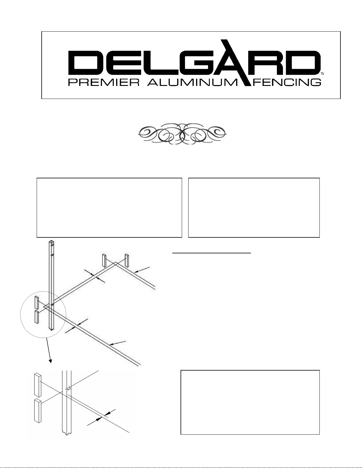
2” STRING LINE
FIGURE 1
2” between property
line and string
(See note above)
PROPERTY
LINE
1. Layout and Planning
1.1. First stake out the area and run strings around
as shown in Figure 1. Gates need to be located
on level ground.
1.2. Proceed to dig post holes approximately 3” to
4” wider than the gate on centers See Figure
2 (on next page) for post hole depth.
1.3. Be sure to separate the gate posts from other
fence posts. Gate posts have a thicker wall
than other fence posts. To prevent your fence
from running short of the next gate post DO
NOT install more than one gate for each line
of fence to be installed. Additional gates will
be installed when the fence reaches the desired
gate location.
THE STRENGTH OF BEAUTY
AERO GRADE GATE INSTALLATION MANUAL
DT3336-60
GIVE THIS MANUAL TO THE HOMEOWNER UPON COMPLETION
CAUTION: In areas where ground frost
occurs extend the concrete footing below
the frost line.
NOTE: Local municipalities may require
different hole depths than those shown
below. You must verify that these depths
meet all local building codes.
1/8” between
post and string

2
FIGURE 2
FIGURE 3
Post Cap
2.3. For a double drive gate installation set the gate opening 2” wider than the actual width of the
two gates. (Example: Two 36” wide gates will actually measure 70” wide overall and will
require the opening to be 72” wide.) See Figure 5.
2.4. Fill the post hole with a stiff concrete mix being sure that the concrete extends below the
bottom of the post.
2.5. Be sure the posts are plumb and the fence slots are facing the correct direction while the
concrete is setting. Brace the posts as necessary while the concrete is setting.
2. Post Installation
2.1. Use a rubber mallet to drive the post caps onto the posts. Be careful not to
damage the post or caps. See Figure 3.
2.2. For a single gate installation set the gate opening 1”wider than the actual
gate. (example: a 36” wide gate actually measures 35” wide and will require
the actual gate opening to be 36” wide.) See Figure 4.
FIGURE 5
2” – 3”
½
”
½
”
Top Rail
Bottom Rail
FIGURE 4 Strengthener
2” – 3”
½” 1” ½”
POST DEPTH
HEIGHT DEPTH
4’ fence ≅16”
4 1/2’ fence ≅20”
5’ fence ≅25”
6’ fence
≅
31”
Set concrete 4” below
ground surface to allow
grass to grow over
See chart at
right
2” – 3” recommended for
easy lawn maintenance. 2”
maximum for pool fence.
Pack concrete 2”
below post or below
frost line whichever
is greater.
8” hole
diamete
r

3
3. Gate Installation
3.1. After the concrete for the post has set the gate may be hung. Place the gate on blocks at
the correct elevation (See figure 2 above).
3.2. Locate the hinges as far apart as possible on the gate and clamp the hinge post leaf to
the post. Verify that the hinge post leaf is completely flush and plumb with the
mounting surface, to avoid binding. Note the direction the gate will open. See Figure 6.
3.3. Attach the hinges to the post by drilling 7/64” pilot holes and fastening with screws
provided.
3.4. Center the gate into the opening and attach to the hinges in the same manner as the
posts. Double drive gates must have the diagonals running as shown in Figure 5.
3.5. If the hinge is to be mounted
on a flat surface you may
need to shim out the hinge
post leafs so that the hinge
does not rub or bind against
the mounting surface. See
Figure 7.
3.6. The screws provided with the
hinge are intended for
securing the hinge to Delgard
posts & gates. If the hinge is
to be mounted to a masonry
column, wood, etc., ask your
local building supply dealer to
recommend the appropriate
fasteners for your mounting
application.
3.7. Test gates for a smooth free
swinging operation, then
proceed to install the latch
hardware as needed.
4. Hinge Adjustment
4.1. To adjust hinge tension, depress the cam with a
5/16” wide tip slotted screwdriver and turn the cam
1/4 turn, then allow the cam to rise to engage the
two dimples. Clockwise increases tension. See
Figure 8 (on next page). Tension the hinges
equally.
4.2. Check with the Building Officials as to local
requirements and adjust as instructed. In the
absence of any local regulations, gates surrounding
a pool or other similar risk, should be adjusted so
gate can be opened 4”, released, and the gate will
latch securely. Repeat 5 times. Note: you must
use a low friction type latch to meet this
requirement.
Note: Like all mechanical devices, with age and
wear, these hinges will require periodic lubrication,
readjustment and eventual replacement.
Just as you manually lock your home for
security, you must also manually verify the gate is
secured each time, as the self-closing motion could be
hampered by wind, an obstruction, etc. Remember,
where children’s safety is involved, double check all
barriers to prevent accidents.
Gate
Leaf
WALL
Shim
Post Leaf
Gate Open Direction
FIGURE 7
Gate swing
direction
Gate
Leaf Hinge
Gate
½”MAX Gate
Post
Fence
Section
FIGURE 6

4
6. Regular Maintenance
6.1. Check for proper gate operation daily. Lubricate or adjust if necessary.
6.2. Keep gate and fence area free of debris and climbable objects.
6.3. Check fasteners for tightness and replace any worn or damaged parts.
4.3. Lubricate the hinges using a graphite based
lubricant. Apply lubricant to the top of each
hinge and remove excess lubricant from
painted surfaces.
5. Drop Rods
5.1. Mount a drop rod guide two (2) inches from
the bottom of the gate by drilling two (2)
7/64” holes and fastening the guide with two
(2) # 6 x 3/4” self-tapping screws. Fasten the
drop rod catch 20 inches above the bottom of
the gate in the same fashion as the guide.
Before fastening the catch, use the drop rod
to align the guide and catch. See Figure 9.
FIGURE 8
FIGURE 9
Drop Rod
Catch
Drop Rod
Guide
DELGARD FENCE COMPANY
8600 RIVER ROAD
DELAIR, NJ 08110-3398 USA
SWIMMING POOL ACCESS GATES: For pedestrian access, use aero gates 48”
wide or less and install them so that they are self-closing and self-latching.
Aero gates over 48” wide should be used for service access only and should be
installed so that they are self-closing and self-latching. They must also be equipped
with a locking device. (Refer to B.O.C.A. specifications and /or local building codes)
Swimming Pool Enclosure Instructions
Table of contents
Other Delgard Indoor Furnishing manuals

Popular Indoor Furnishing manuals by other brands

LHFD
LHFD C1930027 Assembly instructions

Ameriwood HOME
Ameriwood HOME 5680412COM Assembly instruction

Seville Classics
Seville Classics airLIFT OFF65869 quick start guide

Madetec
Madetec FRIZZ SELECT 280 Assembly instructions

Discovery World Furniture
Discovery World Furniture 2935 instructions

Rev-A-Shelf
Rev-A-Shelf 4SH-15-1 installation instructions

Tauris
Tauris DONATA2000 Assembly & instruction manual

Bolia
Bolia Haven Bed product manual

Essentials For Living
Essentials For Living COLLINA Assembly instructions

Next
Next MURPHY 104343 Assembly instructions

mopio
mopio 3-SEATER SOFA Assembly instructions

Happy Babies
Happy Babies B05 Assembly instructions


