Delixi Drives WS-160MX User manual

Foreword
Thank you for choosing the WS-MX Series DC Inverter Manual Metal/ Argon Arc Welder of
Delixi (Hangzhou) Drives Co., Ltd.
Before use WS-MX Series DC Inverter Manual Metal/ Argon Arc Welder, please carefully
read this Manual to ensure correct use. Incorrect use may lead to abnormal operation, failure and
reduction of service life of and even personal injury accidents. Therefore, WS-MX Series DC
Inverter Manual Metal/ Argon Arc Welder you must carefully read this Manual and strictly follow
it. This Manual is a standard Annex, which is must be properly kept after reading for overhauling
and maintaining the WS-MX Series DC Inverter Manual Metal/ Argon Arc Welder in future.
Except Operating Instructions stated herein, this Manual also provides the circuit diagram for
your information. If you have any questions or special requirements on this products, please contact
our local offices or distributors, you also can phone the Customer Service Center of our
headquarters directly, we are at your service.
The contents of this Manual are subject to change without prior notice.
Before unpacking, please carefully read the following contents:
1. Whether the products are damaged, the spare parts are broken and fall off or main body is
scratched during the transportation.
2. Whether the rated value stated on the nameplate of this machine is consistent with your
ordering requirements, as well as the machine ordered, Product Certificate, User’s Manual and
Warranty are within the carton.
Our company has strict Quality Assurance System on the manufacturing and packaging of the
products, in case of any inspection omitted, please immediately contact our Company or your
supplier to deal with it.
Warning
Without written permission,
no reproduction, dissemination
or use of this Manual and its
related contents are allowed,
or you’ll be investigated for
legal responsibility for any
damages.

Table of Contents
Foreword
I Product introduction.........................................................................................................................................- 1 -
II Notice for Safety.............................................................................................................................................- 2 -
III. Technical Parameters....................................................................................................................................- 3 -
IV Installation and Operation.............................................................................................................................- 5 -
V Preparation and operating for welding............................................................................................................- 8 -
5.1 Operating instruction for argon arc welding.................................................................................................- 8 -
5.2 Operating instruction for manual welding....................................................................................................- 8 -
VI. Maintenance .................................................................................................................................................- 13 -
VII. Troubleshooting..........................................................................................................................................- 14 -
VIII. Circuit Diagram .........................................................................................................................................- 16 -

I. Product introduction
- 1 -
I. Product introduction
WS-MX series inverter welder are proven product with stable performance which is
manufactured with advanced invert welding technology. Its operating principle is that converts
operating frequency of 50/60 Hz to direct current, then invert to high frequency at approximate 100
kHz, and performs voltage dropping and rectification by PWM and high power MOS field effect
transistor (MOSFET), and then output high power DC power for welding by PWM. The weight and
size of welder has been reduced and with the efficiency improvement of more than 30% due to
invert technology.
Automatic compensation for network voltage fluctuation may enhance its performance for
fluctuation resistance. It has the following features of easy to arc, stable welding current, rapid
dynamic response, no welding noise, little splashing, no magnetic deviation and artistic welding
seam.
WS-MX Series DC Inverter Manual/Argon Arc Welder has the following features of stable
and reliable operation, high efficiency, small size, light weight and portability.
DC pulse welding will produce artistic and uniform welding seam like fish scales and with
excellent welding effect and little splashing.

II. Notice for Safety
IMPORTANT:
●Do not cut off power in order to prevent damage of machine during
welding.
●Turn off control switch for cutting torch in order to ensure
disconnection of cutting torch and base metal to prevent burning
by electric arc before welding.
●It is necessary to install safety protection switch for electric
leakage.
●The labor protection appliances must be approved by department
of state administration of work safety supervision.
●Operator must be with effective qualification “Welding (gas
cutting) operation for metal” for special operation.
●Do not perform operation with electricity for maintenance and
repair of welding machine!
Electric shock – may cause serious injury
●Install grounding device according to relevant requirements.
●Do not contact live component or electric welding rodwhile skin is exposed, wearing with wet
gloves or in wet clothes.
●Ensure the insulation among you, ground and work piece.
●Ensure your operating position is safe.
Flue gas – it is harmful to health
●Keep head away from flue gas.
●Operator must use ventilation device or air extraction device to prevent breathing of flue gas
while operate manual metal arc welding or manual argon arc welder.
Arc radiation – may damage your eyes and burn your skin
●Wear appropriate mask, optical filter and protective cloth to protect your eyes and body.
●Protect observer by appropriate mask or curtain.
Fire – welding sparks may cause fire. Ensure there is no inflammable material approach to cutting
area and keep safe.
Noise – excessive noise may damage your hearing.
●Protect your ears by ear muff or other hearing protective device.
●Warn observers that noise may damage their hearing.
Fault – seek professional service for fault.
●Troubleshoot according to relevant items of this manual while there are difficulties for
installing and operating.
●If you still not understood after reading or not troubleshoot according to this manual, please
contact your distributor or our service center for professional service immediately.
- 2 -

III. Technical Parameters
- 3 -
III. Technical Parameters
Model WS-160MX WS-200MX
Input power Single-phase, AC 220V±10%
50/60Hz
Single-phase, AC 220V±10%
50/60Hz
Output current (A) 18 30
No-load Voltage (V)56 56
Output current range (A) 10~160 10~200
Rated operating voltage (V) 16.4 18
Load succession rate (%) 35 35
Loss for no load (W) 40 40
Arcing method High frequency arcing High frequency arcing
Efficiency (%) 85 85
Power factor 0.93 0.93
Insulation Level F F
Shell Protection Level IP21S IP21S
Dimension (W×D×H)mm 155ⅹ295ⅹ375 155ⅹ295ⅹ375
Weight (kg) 9 10

III. Technical Parameters
- 4 -
Model WS-250MX WS-315MX WS-400MX
Input power Three-phase, AC380V±10% 50/60Hz
Output current (A) 7.5 9 18
No-load Voltage (V)56 56 56
Output current range (A) 10~250 10~315 10~400
Rated operating voltage (V) 20 22.6 26
Load succession rate (%) 60 60 60
Loss for no load (W) 40 40 40
Arcing method High frequency arcing High frequency arcing High frequency arcing
Efficiency (%) 85 85 85
Power factor 0.93 0.93 0.93
Insulation Level F F F
Shell Protection Level IP21S IP21S IP21S
Dimension (W×D×H)mm 205ⅹ360ⅹ480 355ⅹ470ⅹ580 355ⅹ470ⅹ580
Weight (kg) 16 20 30

IV. Installation and Operation
Base metal
Welding torch
Input cable
Di
str
ib
ut
i
on ca
bi
net
(1PH 220V)
2
Grounding section
ON
OFF CURRENT
(A)
10
30
45
60
85 100
115
130
145
200
POWER O.C
MMA
TIG
of greater than 4mm
Argon inlet
Argon arc welding connection schematic diagram
Welding torch
Input cable
Distribution cabinet
(1PH 220V)
2
Grounding section
ON
OFF CURRENT
(A)
10
30
45
60
85 100
115
130
145
200
POWER O.C
MMA
TIG
of greater than 4mm
Manual welding connection schematic diagram
- 5 -

IV. Installation and Operation
- 6 -
ON
OFF CURRENT
(A)
10
30
45
60
85 100
115
130
145
200
POWER O.C
MMA
TIG
4
5
6
7
8
9
10
3
2
1
14
13
12
11
Front (rear) panel
No. Name of Part Function Description
1 Handle For moving welding machine by operator.
2 Switch Power switch
3 Output negative
electrode
Output negative electrode of welding machine, which connects with base
metal by inverted polarity connection method.
4 Indicator lamp for
power Indicating for power ON/OFF
5 Indicator lamp for
abnormal condition
Indicator lamp for abnormal condition is lighted when over-temperature is
happened inside the welder, and the welder is out of work at this point of
time. The welder will restart when the temperature return to normal and the
indicator lamp will be off automatically. Cut off power when it is over
current. The indicator lamp for over current will be off after power on.
6 Changeover switch Changeover switch for manual/argon arc welding
7 Current adjustment Adjustment for welding current
8 Interface to welding
torch Interface to argon arc welding torch
9 Control socket for
welding torch Socket for controlling welding torch
10 Output positive
electrode
Output positive electrode of welding machine, which connects with welding
torch by inverted polarity connection method, otherwise it connects with work
piece by positive polarity connection method.
11 Fan guard Prevent the ingress of debris
12 Grounding mark To ensure the safety of person, must make sure the bolt is grounded securely.
13 Waterproof
connector It is used to fix cable
14 Argon interface Argon inlet for argon arc welding

IV. Installation and Operation
- 7 -
It is recommended to select cable with larger section in order to reduce voltage drop while
using longer output cable. If welding cable is too long, it may affect the arcing performance and
other system performance of welding machine (e.g. high frequency arcing performance is reduced
or system operation is abnormal). Therefore you should select the cable with recommended length.
(I) Connection for input cable
1)Each welding machine is equipped with one power cable. Connect the power cable to
corresponding power voltage according to the input voltage of welding machine. Do not make
wrong connection.
Power system will be switched into over voltage protection status due to welding operator’s
negligence to connect single phase AC 220V to AC 380V. Please cut off and reconnect power cable
to AC 220V then restart the machine.
The input voltage for WS160/200MX is single phase 220V.
2)Ensure the connections between power cable and power switch or terminals are good and prevent
the effect of oxidation. Measure the power voltage whether it is in the range of fluctuation as
necessary.
(2) Connection for output cable
WS-160MX/200MX/250MX/315MX/400MX:
Connection for argon arc welding:
1)Gas source: connect argon pipe with the copper nozzle of argon which is located at the back of
welding machine. Gas supply pipeline consists of gas bottle, relief flow meter and pipe.
Connecting part for gas pipe should be fixed by clamp or other matters in order to prevent
leakage and the ingress of air.
2)The conductive section of grounding cable for body shell should be not less than 4 mm2. Connect
a cable to ground at the grounding screw which is located at the back of welding machine in
order to prevent static electricity or leak electricity.
3)Connect argon arc welding torch according to attached figure.
4)Fix quick plug of grounding cable with the quick socket on welding machine panel with the mark
of “+”by screwing in clockwise, the other end of cable clamps with work piece.
5)Manual welding: each welding machine is equipped with a pair of quick plugs, the black quick
plug connects with welding torch and the red one connects with grounding clamp. Use hexagonal
plate to fix and ensure good connection between double cables (welding torch and grounding
cable) and quick plugs. Quick plug may be burned out due to the negligence of this point by
some welding operators.
6)In order to ensure good connection, screw the quick plug in clockwise with force after it connects
with quick socket. Otherwise the plug and socket may be burned out for larger current and longer
operating time.
Note: take notice of the polarity for cable connection. General connection for DC welding machine
consists of positive polarity and inverted polarity. Positive polarity connection i.e. work piece
connects with positive electrode and welding torch to negative electrode. On the contrary, inverted
polarity connection i.e. work piece connects with negative electrode, welding torch to positive
electrode.

V. Preparation and operating for welding
5.1 Operating instruction for argon arc welding
1)The indicator lamp for power will be on while turning power switch on front panel to position
“ON”. Turn function switch on the front panel to position of “Argon arc welding”.
2)Turn on the valve of argon bottle and adjust the flow meter to required value.
3)The axial flow fan in the machine will operate and then press control button on welding torch to
activate solenoid valve. Operator may hear the sound of spark discharging caused by high
frequency arcing and see the argon outlet from welding torch.
4)Set appropriate welding current according to the thickness of welding work piece.
5)The distance between tungsten electrode of welding machine and work piece is 2 to 4 mm. Press
control button on welding torch to arc and the sound of spark discharging caused by high
frequency arcing may disappear; then operator may perform welding.
5.2 Operating instruction for manual welding
1)Turn on the power switch on front panel to activate fan.
2)Set the function switch on front panel to position of “Manual welding”.
3)Set appropriate welding current according to the thickness of welding work piece.
Caution
Do not insert or draw cables or connectors while welder is in operation, otherwise it may
be harmful for personnel safety and damage machine. Cut off power first if it is necessary to
do this.
- 8 -

V. Preparation and operating for welding
- 9 -
Schedule: Parameters selection of manual tungsten electrode argon arc welding for stainless
steel sheet (only for information)
Thickness
(mm) Welding
joint
Diameter of
tungsten
electrode
(mm)
Diameter of
welding wire
(mm) Current Welding
current (A) Argon flow
(L/min) Welding speed
(cm/min)
1.0 Butt joint 2 1.6 DC positive polarity
connection 7~28 3~15 12~47
1.2 Butt joint 2 1.6 DC positive polarity
connection 15 3~15 25
1.5 Butt joint 2 1.6 DC positive polarity
connection 5~19 3~15 8~32
Schedule: Parameters selection of manual tungsten electrode argon arc welding for titanium
and titanium alloy (only for information)
Thickness
(mm) Groove Welding
layer
Diameter of
tungsten
electrode
Diameter of
welding
wire
Welding
current Argon flow (L/min) Nozzle
diameter
0.5
1.0
1.5
2.0
2.5
I Groove
1
1
1
1
1
1.5
2.0
2.0
2.0~3.0
2.0~3.0
1.0
1.0~2.0
1.0~2.0
1.0~2.0
2.0
30~50
40~60
60~80
80~110
110~120
8~10
8~10
10~12
12~14
12~14
6~8
6~8
8~10
10~12
10~12
14~16
14~16
14~16
16~20
16~20
10
10
10~12
12~14
12~14
3.0
4.0
5.0
6.0
7.0
8.0
Y Groove
1~2
2
2~3
2~3
2~3
3~4
3.0
3.0~4.0
4.0
4.0
4.0
4.0
2.0~3.0
2.0~3.0
3.0
3.0~4.0
3.0~4.0
3.0~4.0
120~140
130~150
130~150
140~180
140~180
140~180
12~14
14~16
14~16
14~16
14~16
14~16
10~12
12~14
12~14
12~14
12~14
12~14
16~20
20~25
20~25
25~28
25~28
25~28
14~18
18~20
18~20
18~20
20~22
20~22
10
20
22
25
30
Dual Y Groove
4~6
12
12
15~16
17~18
4.0
4.0
4.0
4.0
4.0
3.0~4.0
4.0
4.0~5.0
3.0~4.0
3.0~4.0
160~200
200~240
230~250
200~220
200~220
14~16
12~14
15~18
16~18
16~18
12~14
10~12
18~20
20~26
20~26
25~28
20
18~20
26~30
26~30
20~22
18
20
22
22

V. Preparation and operating for welding
Schedule: Parameters selection of manual tungsten electrode argon arc welding for aluminum
and aluminum alloy (only for information)
Thickness
(mm) Groove Welding layer
(front/back)
Diameter of
tungsten
electrode
(mm)
Diameter of
welding
wire
Preheating
temperature
()℃
Welding
current Argon
flow
Nozzle
diameter
(mm)
1.5
2 I Groove 1/0
1/0 2
2~3 1.6~2.0
2~2.5 _
_ 50~80
50~80 7~9
8~12 8
8~12
3
4
5
8
10
12
16
20
Y Groove
1/0
1~2/1
1~2/1
2/1
3~4/1~2
3~4/1~2
4~5/1~2
4~5/1~2
3
4
4
5
5
5~6
6
6
2~3
3
3~4
4~5
4~5
4~5
5~6
5~6
_
_
_
100
100~150
150~200
200~220
200~260
15~180
180~200
180~240
260~320
280~340
300~360
340~380
360~400
8~12
10~15
10~15
16~20
16~20
18~22
20~24
25~30
8
8~12
8~12
10~12
14~16
14~16
16~20
20~22
16~20
22~25 Dual Y Groove 2~3/2~3
2~3/2~3 6
6~7 5~6
5~6 200~260
200~260 300~380
360~400 25~30
30~35 16~20
20~22
Possible problems in welding process
Following phenomenon may be related to the accessories, gas, environmental factor and power
supply condition used. Please improve operating condition to prevent theses phenomenon
occurrence.
A.Welding point darkening
——This phenomenon indicates that welding joint is oxidized without taking effective protection
measures. You can check as follow:
1. Confirm valve of argon bottle is opened and with sufficient pressure. Generally, refill argon if
internal pressure of argon bottle is less than 0.5 MPa.
2. Check the flow valve for argon whether is opened and with sufficient pressure. In order to save
argon, you may select different flow according to the actual welding current, but lower flow may
cause welding point not covered by protective gas completely. It is recommended that the argon
flow should be not less than 5 L/min regardless of the current.
3. The simplest method for checking gas flow is that feel the gas on the nozzle of welding torch by
hand and check whether the pipeline of welding torch is blocked.
4. Bad sealing performance of pipeline or lower purity may affect welding quality.
5. Strong air flow in operating condition may affect welding quality as well.
6. Adjustment for duty ratio is too low.
B.It is difficult to arc and easy to break.
- 10 -

V. Preparation and operating for welding
1. Confirm the quality of tungsten electrode is good. The discharge performance of tungsten
electrode in bad quality may not meet relevant requirement.
2. The tungsten electrode without sharp treatment is not easy to arc and may cause arc to be
unstable.
C.The current may be unstable during machine operation.
This condition may be related to following factors: 1. Change of network voltage. 2.
Interference by network or other electrical equipments.
Precaution or preventive measures
1. Environment
1)Welding operation must be preformed in a dry condition with air humidity of not greater than
90%.
2)Ambient temperature range between -10 to 40℃℃.
3)Do not operate welder in sunshine or in the rain to prevent the ingress of water or rainwater.
4)Do not operate welder in the environment with dust or corrosive gas.
5)Do not perform gas protective welding in the environment with strong air flow.
2. Keys to Safety
This welder is equipped with protection circuits for over current and over heating. System will
shut down if network voltage, output current and inside temperature exceed setting value. Excessive
operation may damage welder as well (e.g. voltage is higher), therefore you must be in accordance
with following:
1)Good ventilation!
During the operation of WS-MX series welding machine, nature ventilation may not meet the
cooling requirements of welder due to the larger current. Therefore it is necessary to set a fan inside
to cool and ensure its stable operation.
In order to ensure good ventilation, welding operator must ensure air vent is not covered or
blocked and the distance between welder and surrounding objects should be not less than 0.3 meter.
Above items are important for the operation and service life of welder.
2)Do not overload!
Welding operator should observe the max. allowable load current (relative to load succession
rate) and maintain welding current not greater than max. allowable load current.
Over current may shorten service life of welder obviously or even burn it out.
- 11 -

V. Preparation and operating for welding
- 12 -
3)Do not over voltage!
Power voltage listed in “main performance parameters list”. Generally, automatic
compensation circuit in welder may maintain welding current within allowable range required for
normal operation. However, it may damage welder if power voltage exceeds power voltage.
Operator must observe above condition and take proper preventive measures.
4)Each welder is equipped with a grounding bolt behind machine and grounding mark. Select a
cable with the section of not less than 4 mm2to discharge static electricity or prevent electric
leakage for grounding of welder before operating.
5)Welder will enter into protection status and stop operating if it exceeds the standard load
succession rate. It indicates that excessive heat activates the temperature control switch to stop
operating of welder, and red indicator lamp is on at front panel. During this condition, do not
remove power plug and maintain cooling fan inside to operate to cool the power device. If yellow
indicator lamp is off, it indicates that temperature is drop to normal range, system is back to
normal.

VI. Maintenance
- 13 -
VI. Maintenance
1)Purge inside by dry and clean compressed air regularly. Remove dust every month if welder is
operated in the environment of heavy smoke and serious air pollution.
2)Pressure of compressed air should be maintained within a applicable range in order to prevent
damage of small element inside.
3)Check circuit connections inside regularly in order to ensure correct connection and firm
connectors (especially for inserted connector or element). Remove rust and oxidation film by
abrasive paper if they are rusty and looseness, and then reconnect and fix
4)Prevent the ingress of water or water vapor for welder. Dry it if there is water or water vapor.
And then measure the insulation condition of cutting machine by megameter (including space
between connecting points and space between connecting point and body shell). Perform welding
operation after ensure they are normal.
5)Store welder in the original package and place it in dry condition if it is not used for long time.

VII. Troubleshooting
1. Free maintenance assurance may be failure if customer repair any fault of welding
machine by themselves without our authorization during warranty period.
2. Following operations require enough professional knowledge on electric and comprehensive
knowledge on safety. Operator should be with required knowledge and relevant qualification.
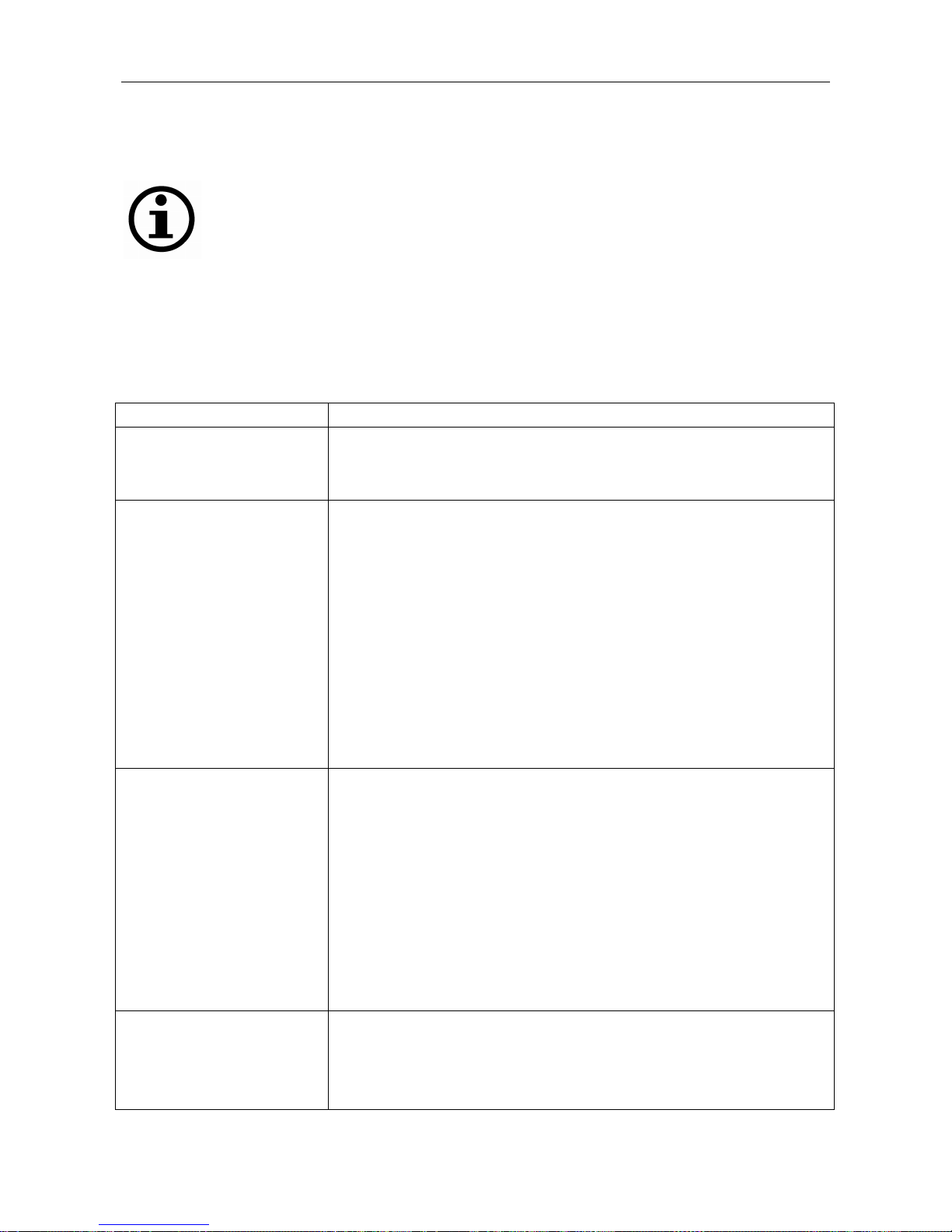
I. Fault and Troubleshooting
Fault Troubleshooting
1. Indicator lamp for power is
off, fan is not operating and
without welding output
1. Power switch is damaged
2. Ensure network connected with input cable is live or not.
3. Ensure input cable is open or not.
2. Indicator lamp for power is
on, fan is not operating or
operating for a while and
without welding output.
1. Connect with 380V power by mistake to cause it activate over voltage
protection circuit. Reconnect with 220V power and restart.
2. 220V power is unstable (input cable is too long) or connect with network to
cause it activate over voltage protection circuit. Increase the diameter of
input cable or joint for fixing input cable. Shut down and restart after 2 to 3
minutes.
3. Connect power switch for on and off in short time to cause it activate over
voltage protection circuit. Shut down and restart after 2 to 3 minutes.
4. Wire between switch and power panel is looseness and fix them again.
5. 24V relay in main circuit is not engaged or damaged. Check 24V power and
relay. Replace it by same model one if relay is damaged.
3. Fan is operating and
indicator lamp for fault is
off, without rustle caused by
high frequency discharging.
No arcing when struck.
1. The voltage between positive and negative poles of VH-70 plug on MOS
plate and power plate should be DV 308 V measured by multimeter.
(1) Whether there is open circuit or bad wire connection of silicon bridge.
(2) Whether there is creepage to one or any of four big electrolytic capacitor
(470UF/400Vapprox.) on the power plate, replace it if any.
2. Auxiliary power is fault if the green indicator lamp for auxiliary power on
MOS plate is off. Check fault point and contact distributor.
3. Check any poor contact for each wire.
4. Control circuit is fault. Check reason and contact distributor.
5. Control cable of welder is broken.
4. Indicator lamp for fault is off
and with rustle caused by
high frequency discharging.
No welding output.
1. Cable of welder is damaged.
2. Grounding cable is damaged or not connects with work piece to be welded.
3. Connections for positive output terminals or gas and electric output terminals
of welding torch are looseness.
- 14 -

VII. Troubleshooting
- 15 -
5. Indicator lamp for fault is off
and with rustle caused by
high frequency discharging.
Arcing when struck.
1. Poor contact between primary wire of arcing transformer and power plate.
Refix it.
2. Discharge nozzle is oxidized or too long. Remove the surface oxidation film
of discharge nozzle or adjust the distance of discharge nozzle to 1 mm.
3. Changeover switch of manual and argon arc welding is damaged. It is need to
be replaced.
4. Some elements of high frequency arcing circuit are damaged. Check and
replace.
6. Indicator lamp for fault is on
but without output.
1. Over current protection. Shut down and restart after indicator lamp for fault is
off.
2. Overheating protection. Do not shut down and wait for 2 to 3 minutes.
3. Inverter circuit is fault. Remove power plug for main transformer on MOS
plate (close to fan VH-07 inserter) and restart.
(1) Indicator lamp for fault is still on. Shut down and remove high frequency
arcing power plug (close to fan VH-03 inserter) and restart.
a. Indicator lamp for fault is on due to some field effect transistors on MOS plate
are damaged. Check and replace the same type field effect transistor.
b. Indicator lamp for fault is off due to step up transformer of high frequency
arcing circuit is damaged and need to be replaced.
(2) Indicator lamp for fault is off.
a. Medium transformer is damaged. Measure the primary inductance and Q
value of transformer by electric bridge. If L=0.9-1.6mH, Q>35 as well as
inductance and Q value is very small, replace it.
b. Some transformer secondary rectifying tubes are penetrated. Check and
replace by same type.
4. Feedback circuit is opened.
7. Output current is unstable or
not controlled by
potentiometer during
welding.
1. IK potentiometer is damaged and need to be replaced.
2. Check poor contact for each connection especially for connector etc.
8. Alkaline welding rod is
difficult to operate due to
serious splashing for manual
welding.
1. Polarity connection is wrong and it is need to change the polarity of grounding
cable and welding torch cable.

VIII. Circuit Diagram
Drive circuit
High frequency
arcing circuit
Protection
circuit Control circuit Sampling circuit
Auxiliary circuit
Functional block diagram for the Models smaller than WS – 200MX
Drive circuit
High frequency
arcin
g
circuit
Control circuit
Protection
circuit
Sampling
circuit
Auxiliary
circuit
Functional block diagram for models greater than WS – 250MX
- 16 -
This manual suits for next models
9
Table of contents
Popular Inverter manuals by other brands

WINDY NATION
WINDY NATION VertaMax Series user manual

Ingeteam
Ingeteam INGECON SUN EMS Board Configuration manual

R&S
R&S SMB100A operating manual

Zipper Mowers
Zipper Mowers ZI-STE1100IV user manual

enphase
enphase IQ 7+ Installation and operation manual

IO-Power Technology
IO-Power Technology IOP-DAPI-12243A-2 user manual