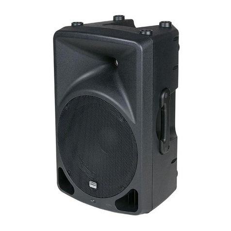
Delphi Display Systems Endura 15X User manual

Delphi Display Systems, Inc. RDS-INS15XSSP, Rev, A Page 1 of 19
Confidential Document:
Do not copy or distribute without written permission. Unpublished Work 20186 Delphi Display Systems, Inc. All rights reserved.
Printed copies are Uncontrolled unless clearly marked as a Controlled document. User responsible for verifying document is the current revision.
Title: Endura 15X OCS 15” Speaker Post Installation Instructions Doc Number: RDS-INS15XSSP
Revision: A
Department: Sales
Area:
Training
Approved and released Effective Date: 10/25/2016
Review Period: 365 days
Order Confirmation System (OCS)
Speaker Post Installation Instructions
Delphi Display Systems, Inc.
PROPRIETARY INFORMATION

Delphi Display Systems, Inc. RDS-INS15XSSP, Rev, A Page 2 of 19
Confidential Document:
Do not copy or distribute without written permission. Unpublished Work 20186 Delphi Display Systems, Inc. All rights reserved.
Printed copies are Uncontrolled unless clearly marked as a Controlled document. User responsible for verifying document is the current revision.
This page intentionally left blank

Delphi Display Systems, Inc. RDS-INS15XSSP, Rev, A Page 3 of 19
Confidential Document:
Do not copy or distribute without written permission. Unpublished Work 20186 Delphi Display Systems, Inc. All rights reserved.
Printed copies are Uncontrolled unless clearly marked as a Controlled document. User responsible for verifying document is the current revision.
Table of Contents
1
INTRODUCTION ............................................................................................................................................... 5
1.1
S
PEAKER
P
OST
M
OUNTING
O
PTION
................................................................................................................ 5
1.2
T
ECHNICAL
S
UPPORT
..................................................................................................................................... 5
2
REQUIRED TOOLS ........................................................................................................................................... 5
3
SITE PREPARATION ........................................................................................................................................ 6
3.1
S
ELECT
L
OCATION FOR THE
S
PEAKER
P
OST
................................................................................................... 6
3.2
C
ONDUITS
....................................................................................................................................................... 6
3.3
F
OOTING AND
A
NCHOR
B
OLTS
....................................................................................................................... 6
3.4
A
NCHOR
B
OLT
I
NSTALLATION
–
N
EW
I
NSTALLATION
.................................................................................... 7
3.4.1
Retrofit of an Existing OCS ................................................................................................................... 7
3.5
R
UNNING THE
E
LECTRICAL
W
IRING
–
N
EW
I
NSTALLATION
........................................................................... 8
3.6
R
UNNING THE
D
ATA AND
A
UDIO
C
ABLES
–
N
EW
I
NSTALLATION
.................................................................. 8
4
MOUNTING THE SPEAKER POST ................................................................................................................ 8
4.1
E
LECTRICAL
C
ONNECTIONS
–
C
ONDUIT
M
OUNTED
J
UNCTION
B
OX
............................................................. 11
4.2
E
LECTRICAL
C
ONNECTIONS
–
S
PEAKER
P
OST
M
OUNTED
J
UNCTION
B
OX
.................................................... 11
4.3
C
IRCUIT
B
REAKER
L
ABELING
....................................................................................................................... 13
4.4
S
PEAKER
I
NSTALLATION
U
SING
N
EW OR
E
XISTING
E
LEMENTS
.................................................................... 13
4.5
M
ICROPHONE
I
NSTALLATION
U
SING
N
EW OR
E
XISTING
E
LEMENTS
............................................................. 13
4.6
C
ONNECTING THE
A
UDIO
C
ABLES
................................................................................................................ 13
5
OCS DISPLAY MODULE INSTALLATION ................................................................................................ 14
5.1
I
NSTALLING THE
OCS
D
ISPLAY
M
ODULE IN THE
S
PEAKER
P
OST
................................................................. 14
5.2
C
ONNECTING THE
D
ATA
C
ABLE
(
S
) ............................................................................................................... 16
5.3
C
ONNECTING THE
P
OWER
C
ABLE
................................................................................................................. 17
5.4
S
ECURING THE
B
ACK
P
ANEL
........................................................................................................................ 17
6
CABLE CONNECTIONS INSIDE THE STORE .......................................................................................... 17
7
CHANGE HISTORY ........................................................................................................................................ 18
8
APPENDIX A - FOOTING AND CONDUIT SPECIFICATIONS................................................................. 1

Delphi Display Systems, Inc. RDS-INS15XSSP, Rev, A Page 4 of 19
Confidential Document:
Do not copy or distribute without written permission. Unpublished Work 20186 Delphi Display Systems, Inc. All rights reserved.
Printed copies are Uncontrolled unless clearly marked as a Controlled document. User responsible for verifying document is the current revision.
Table of Figures
F
IGURE
1
–
A
NCHOR
B
OLT
K
IT AND
T
EMPLATE
............................................................................................................. 6
F
IGURE
2
-
C
OMPLETED
F
OOTING
................................................................................................................................... 7
F
IGURE
3
-
L
OCK ON
B
ACK OF
S
PEAKER
P
OST
............................................................................................................... 8
F
IGURE
4
-
S
ETTING THE
P
OST
........................................................................................................................................ 9
F
IGURE
5
-
E
XAMPLE OF
U
SING
S
HIMS
......................................................................................................................... 10
F
IGURE
6
-
E
NSURE
P
OST IS
L
EVEL
............................................................................................................................... 10
F
IGURE
7
-
L
OWER
N
IPPLE FOR
AC
E
LECTRICAL
C
ONNECTION
.................................................................................... 11
F
IGURE
8
-
I
NCOMING
AC
E
LECTRICAL
R
OUTED
I
NTO
J
UNCTION
B
OX
........................................................................ 12
F
IGURE
9
-
C
ONNECT
I
NCOMING
AC
P
OWER PER LOCAL CODE AND
NEC .................................................................... 12
F
IGURE
10
-
AC
C
ONNECTION
C
OMPLETE
,
J
UNCTION
B
OX
S
EALED
............................................................................. 12
F
IGURE
11
-
E
XAMPLES OF
P
ROPERLY
L
ABELED
C
IRCUIT
B
REAKER
............................................................................ 13
F
IGURE
12
-
S
PEAKER
A
SSEMBLY
I
NSTALLATION
........................................................................................................ 13
F
IGURE
13
-
D
ETAIL OF
A
LIGNMENT
A
NGLE
S
TOP
....................................................................................................... 14
F
IGURE
14
-
I
NSERT
E
NDURA
15X
AT AN ANGLE
.......................................................................................................... 14
F
IGURE
15
-
E
NDURA
15X
I
NSERTED
O
NTO
S
HELF
....................................................................................................... 15
F
IGURE
16
-
S
TRAPS
I
NSERTED
.
A
TTACH
2
N
UTS TO
S
ECURE
...................................................................................... 15
F
IGURE
17
-
T
IGHTEN
#10
N
UTS WITH
5/16"
D
RIVER
................................................................................................... 16
F
IGURE
18
-
W
ATERTIGHT
C
ONNECTION
...................................................................................................................... 16
F
IGURE
19
-
I
NSERT
P
OWER
C
ONNECTOR
..................................................................................................................... 17
F
IGURE
20
-
B
ACK
P
ANEL
............................................................................................................................................ 17

Delphi Display Systems, Inc. RDS-INS15XSSP, Rev, A Page 5 of 19
Confidential Document:
Do not copy or distribute without written permission. Unpublished Work 20186 Delphi Display Systems, Inc. All rights reserved.
Printed copies are Uncontrolled unless clearly marked as a Controlled document. User responsible for verifying document is the current revision.
1 Introduction
This document describes the installation procedure for the Delphi Order Confirmation System (OCS) Speaker Post
and is used in conjunction with other installation manuals which vary based on specific customer or system
requirements. This manual covers only preparation for and installation of the speaker post; which includes installing
the microphone, speaker and OCS into the post.
1.1 Speaker Post Mounting Option
The Speaker Post has been designed as a free standing integrated mounting system for the 9330 Series displays and
audio system speakers. The Speaker Post will accommodate a wide variety of speaker systems in either full or half
duplex configurations. The Speaker Post is constructed of aircraft quality aluminum 6061 and has been designed to
be aesthetically pleasing as well as durable and easy to install.
1.2 Technical Support
For technical assistance, please contact:
Delphi Display Systems, Inc.
3160 Pullman St.
Costa Mesa, CA 92626
Toll Free: (800) 456-0060
Email: tec[email protected]
2 Required Tools
The following is a list of required tools. Some tools may not be required for all installations.
3/8" drive ratchet
3/4" deep well socket
3/4" open end wrench
10" #2 Philips screwdriver
5/16" nut driver
3/8” nut driver
Wire Strippers
Portable soldering iron
200' fish tape
Cordless Drill/Driver
Hammer
Multi-Meter
Hammer Drill - for use when installing new bolts in an existing concrete pad.
Level

Delphi Display Systems, Inc. RDS-INS15XSSP, Rev, A Page 6 of 19
Confidential Document:
Do not copy or distribute without written permission. Unpublished Work 20186 Delphi Display Systems, Inc. All rights reserved.
Printed copies are Uncontrolled unless clearly marked as a Controlled document. User responsible for verifying document is the current revision.
3 Site Preparation
This section describes the steps necessary to properly prepare the site for installation of the Delphi OCS Speaker
Post. Please read the entire section before beginning any work. The following items must be completed prior to
installation of the OCS Speaker Post.
3.1 Select Location for the Speaker Post
The OCS Speaker Post has been designed so that the display is positioned at the optimum height for most vehicles
when the bottom of the speaker post is level with the top of the curb near the vehicle. Refer to Appendix A when
selecting a location for distance specs. The speaker post must be placed in a position where the customer can see
both the OCS and the menu board clearly. If the speaker and microphone are to be installed in the speaker post, be
sure to select a position where an optimal audio condition can be maintained. Consider the underground vehicle
detector (loop) also. The center line position in front of the speaker post must be within 18” of the loop. If it is not,
a new loop may be necessary.
3.2 Conduits
A minimum of three (3) conduits must be run to the OCS Speaker Post; one for a dedicated electrical circuit, one for
audio cables and another for the data cables. Ensure that the conduits will be centered in the bolt pattern. Refer to
Appendix A for detailed specifications.
3.3 Footing and Anchor Bolts
Before pouring the footing, make sure that all of the conduit has been run and is in the correct locations. Locate the
anchor bolt mounting kit and verify the following contents shown in the figure below.
Four (4) each ½” ‘J’ anchor bolts
Eight (8) each ½” zinc plated hex nuts
Eight (8) each ½” zinc plated flat washers
One (1) each anchor bolt template
Figure 1 – Anchor Bolt Kit and Template

Delphi Display Systems, Inc. RDS-INS15XSSP, Rev, A Page 7 of 19
Confidential Document:
Do not copy or distribute without written permission. Unpublished Work 20186 Delphi Display Systems, Inc. All rights reserved.
Printed copies are Uncontrolled unless clearly marked as a Controlled document. User responsible for verifying document is the current revision.
3.4 Anchor Bolt Installation – New Installation
Install the ½” anchor “J” bolts into the template and secure with the ½” nuts and washers. This will insure the
alignment of the mounting bolts in the concrete. Pour the concrete footing and locate the anchor bolts in the correct
position using the alignment tool. Make sure to keep the anchor bolt threads clean and finish the surface of the
concrete as smooth and level as possible. A properly installed footing, anchor bolts, and conduits should resemble
the one in the picture below.
Figure 2 - Completed Footing
3.4.1 Retrofit of an Existing OCS
In many retrofit installations, existing slabs may be used to mount the OCS Speaker Post. The footing must be at
least 12” wide by 12” deep and of sufficient depth to support the OCS Speaker Post. It may be necessary to remove
existing anchor bolts and install new ones to match up to the base plate mounting hole pattern. Verify that the
existing conduits will be centered within the bolt pattern.
Some installations may have conduits that have been run outside the existing speaker post. In these cases, conduit
can be run into the back of the speaker post utilizing the provided “knock outs”. If the “knock outs” are not in the
correct position to be used, you may cut your own “knock out” in the bottom of the back of the speaker post. DO
NOT PUNCH A HOLE AND EXTEND THE CONDUIT. You must cut the bottom edge of the post out. If you
do not, it will not be possible to remove the speaker post without first removing the conduit from the post.

Delphi Display Systems, Inc. RDS-INS15XSSP, Rev, A Page 8 of 19
Confidential Document:
Do not copy or distribute without written permission. Unpublished Work 20186 Delphi Display Systems, Inc. All rights reserved.
Printed copies are Uncontrolled unless clearly marked as a Controlled document. User responsible for verifying document is the current revision.
3.5 Running the Electrical Wiring – New Installation
The OCS Speaker Post must be wired to a dedicated circuit on an isolated ground with the Point of Sale (POS)
system. Pull the electrical wiring in accordance with NEC and local building codes. Terminate the electrical wiring
with a standard single-gang junction box.
3.6 Running the Data and Audio Cables – New Installation
The data cable is provided by Delphi Display Systems and is pre-terminated on the OCS end with a weather proof
connector. Pull the data cable through the appropriate conduit starting at the OCS end. Leave five (5) feet of cable
protruding from the end of the conduit. This will allow enough cable to route up through the speaker post and
connect to the back of the display module. Do not under any circumstances leave any more than 5’ of data
cable inside of the speaker post.
4 Mounting the Speaker Post
Remove the back panel of the Speaker Post by using the supplied key to unlock the back panel.
Figure 3 - Lock on Back of Speaker Post
Lock on back of post.
Key located inside front of
Speaker Post in a plastic
bag tie strapped to the
mounting bracket

Delphi Display Systems, Inc. RDS-INS15XSSP, Rev, A Page 9 of 19
Confidential Document:
Do not copy or distribute without written permission. Unpublished Work 20186 Delphi Display Systems, Inc. All rights reserved.
Printed copies are Uncontrolled unless clearly marked as a Controlled document. User responsible for verifying document is the current revision.
Install the speaker post over the bolts and conduits. Level the base plate and fasten with four (4) ½” nuts. If the
footing is not level, the base plate can be leveled using the supplied leveling shims around the bolts between the
speaker post and footing. After the speaker post is level, secure the bolts with the nuts provided.
Figure 4 - Setting the Post

Delphi Display Systems, Inc. RDS-INS15XSSP, Rev, A Page 10 of 19
Confidential Document:
Do not copy or distribute without written permission. Unpublished Work 20186 Delphi Display Systems, Inc. All rights reserved.
Printed copies are Uncontrolled unless clearly marked as a Controlled document. User responsible for verifying document is the current revision.
Figure 5 - Example of Using Shims
Figure 6 - Ensure Post is Level

Delphi Display Systems, Inc. RDS-INS15XSSP, Rev, A Page 11 of 19
Confidential Document:
Do not copy or distribute without written permission. Unpublished Work 20186 Delphi Display Systems, Inc. All rights reserved.
Printed copies are Uncontrolled unless clearly marked as a Controlled document. User responsible for verifying document is the current revision.
4.1 Electrical Connections – Conduit Mounted Junction Box
Use this section only if the electrical junction box is mounted at the top of the conduit.
First and foremost, make sure that the circuit breaker for the electrical supply wires is turned off. The OCS power
supply is already installed inside the post and has 2 pigtails hanging from it. This makes the electrical connection
very easy. Guide the OCS power supply pigtails into the junction box through a knockout and seal it with TBD.
Terminate the OCS power supply pigtails to the incoming electrical supply lines in accordance with NEC and local
building codes.
Safety Warnings
1. Verify that the circuit breaker has been turned off. If uncertain about the wiring, contact an electrician.
2. Follow all manufacturers’ instructions for your tools.
3. Make sure all wires are properly connected and covered.
4. Observe all applicable codes and ordinances.
4.2 Electrical Connections – Speaker Post Mounted Junction Box
Use this section only if the electrical junction box is mounted in the speaker post.
First and foremost, make sure that the circuit breaker for the electrical supply wires is turned off. The OCS power
supply is already installed inside the post and is pre-wired to the junction box, already mounted in the speaker post.
This makes the electrical connection very easy. Remove the two face screws and open the junction box. Remove
the lower nipple for AC inlet power connection. Route the incoming electrical supply lines through the lower nipple
and into the bottom of the junction box. Re-attach the lower nipple and tighten to form a water tight seal.
Terminate the OCS power supply pigtails to the incoming electrical supply lines in accordance with NEC and local
building codes. Finally, re-attach the waterproof cover to the junction box.
Safety Warnings
1. Verify that the circuit breaker has been turned off. If uncertain about the wiring, contact an electrician.
2. Follow all manufacturers’ instructions for your tools.
3. Make sure all wires are properly connected and covered.
4. Observe all applicable codes and ordinances.
Figure 7 - Lower Nipple for AC Electrical Connection

Delphi Display Systems, Inc. RDS-INS15XSSP, Rev, A Page 12 of 19
Confidential Document:
Do not copy or distribute without written permission. Unpublished Work 20186 Delphi Display Systems, Inc. All rights reserved.
Printed copies are Uncontrolled unless clearly marked as a Controlled document. User responsible for verifying document is the current revision.
Figure 8 - Incoming AC Electrical Routed Into Junction Box
Figure 9 - Connect Incoming AC Power per local code and NEC
Figure 10 - AC Connection Complete, Junction Box Sealed

Delphi Display Systems, Inc. RDS-INS15XSSP, Rev, A Page 13 of 19
Confidential Document:
Do not copy or distribute without written permission. Unpublished Work 20186 Delphi Display Systems, Inc. All rights reserved.
Printed copies are Uncontrolled unless clearly marked as a Controlled document. User responsible for verifying document is the current revision.
4.3 Circuit Breaker Labeling
Delphi supplies a sticker with every new installation that is to be used to mark the correct circuit breaker that
supplies power to the OCS. The sticker is affixed to the back of all new displays near the power connection. This
sticker is to be placed directly on the correct circuit breaker, but not in a way that impedes the use of the breaker. If
the sticker is not supplied, the installer is to mark the circuit breaker with a permanent marker. See figure below for
examples of both.
Figure 11 - Examples of Properly Labeled Circuit Breaker
4.4 Speaker Installation Using New or Existing Elements
Locate the speaker housing which is the box in the bottom half of the speaker post. Remove the four nuts from the
sides of the assembly using a 5/16” driver. This will allow you to remove the box. Use high density foam (display
packing material) to partially fill the speaker box. Place the speaker element into the cavity facing out. Use more
foam to pack around the speaker element filling the cavity. Place the speaker box back into position and replace all
four nuts.
Figure 12 - Speaker Assembly Installation
4.5 Microphone Installation Using New or Existing Elements
Locate the microphone box which is located in the top half of the speaker post. The microphone element is installed
in the same manner as the speaker was in the previous Section.
4.6 Connecting the Audio Cables
Connect the Speaker/Mic and/or Speaker cables per the audio system supplier specifications. Allow enough service
loop to remove the speaker boxes if necessary.

Delphi Display Systems, Inc. RDS-INS15XSSP, Rev, A Page 14 of 19
Confidential Document:
Do not copy or distribute without written permission. Unpublished Work 20186 Delphi Display Systems, Inc. All rights reserved.
Printed copies are Uncontrolled unless clearly marked as a Controlled document. User responsible for verifying document is the current revision.
5 OCS Display Module Installation
Carefully unpack the Display Module and inspect for any signs of damage. If any damage is visible, please contact
Delphi Display Systems, Inc. immediately.
5.1 Installing the OCS Display Module in the Speaker Post
Remove the two nuts securing the tops of the mounting straps and set the mounting straps and nuts aside.
Carefully insert the Display Module into the rear of the speaker post by angling it slightly. Set the Display Module
on the internal shelf and gently slide it to the left until it is aligned with the angled stop on the internal shelf. Re-
insert the mounting straps, and secure them with the two #10 nuts, taking care to tighten them with the 3/8” nut
driver. Do not over-tighten the nuts.
Figure 13 - Detail of Alignment Angle Stop
Figure 14 - Insert Endura 15X at an angle

Delphi Display Systems, Inc. RDS-INS15XSSP, Rev, A Page 15 of 19
Confidential Document:
Do not copy or distribute without written permission. Unpublished Work 20186 Delphi Display Systems, Inc. All rights reserved.
Printed copies are Uncontrolled unless clearly marked as a Controlled document. User responsible for verifying document is the current revision.
Figure 15 - Endura 15X Inserted Onto Shelf
Figure 16 - Straps Inserted. Attach 2 Nuts to Secure

Delphi Display Systems, Inc. RDS-INS15XSSP, Rev, A Page 16 of 19
Confidential Document:
Do not copy or distribute without written permission. Unpublished Work 20186 Delphi Display Systems, Inc. All rights reserved.
Printed copies are Uncontrolled unless clearly marked as a Controlled document. User responsible for verifying document is the current revision.
Figure 17 - Tighten #10 Nuts with 3/8" Driver
5.2 Connecting the Data Cable(s)
***The data cables are not to be connected to the back of the display until ALL of the cables have been terminated.
Be sure to install the watertight connector kit (see Endura 15X Installation Manual) before connecting to the
leftmost connector on the back of the display. Be sure to turn the locking nut all the way to ensure a good watertight
connection. See figure below.
Figure 18 - Watertight Connection

Delphi Display Systems, Inc. RDS-INS15XSSP, Rev, A Page 17 of 19
Confidential Document:
Do not copy or distribute without written permission. Unpublished Work 20186 Delphi Display Systems, Inc. All rights reserved.
Printed copies are Uncontrolled unless clearly marked as a Controlled document. User responsible for verifying document is the current revision.
5.3 Connecting the Power Cable
The LOW VOLTAGE power supply is already installed into the speaker post.
Plug the proper end in the back of the display and BE SURE to screw it down so it can maintain a watertight
connection.
Figure 19 - Insert Power Connector
5.4 Securing the Back Panel
Check to make sure all cables are installed securely and routed properly.
Figure 20 - Back Panel
Install the rear Speaker Post cover plate and lock it in place. Clean up the area around the Speaker Post.
****Be sure to leave the key with the store so they may get into the Speaker Post as needed****
6 Cable Connections inside the Store
Please refer to the Display Module Installation Manual for instructions on how to do all cabling inside the store.

Delphi Display Systems, Inc. RDS-INS15XSSP, Rev, A Page 18 of 19
Confidential Document:
Do not copy or distribute without written permission. Unpublished Work 20186 Delphi Display Systems, Inc. All rights reserved.
Printed copies are Uncontrolled unless clearly marked as a Controlled document. User responsible for verifying document is the current revision.
7 Change History
Change Version Date Author
Initial Release
A
10/25/2016

Confidential Document:
Do not copy or distribute without written permission from Delphi Display Systems, Inc.
Copyright 2016. [Unpublished Work]. All rights reserved
.
8 Appendix A - Footing and Conduit Specifications
Table of contents

