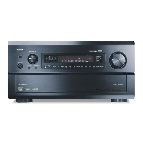
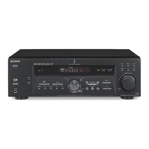
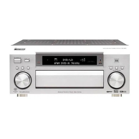
Demon AVR-3600 User manual

DEMON
AV
SURROUND
RECEIVER
AVR-3600
We
areatlv
appreciate
your
purchase
of
the
AVR-3600.
To
be
sure
you
take
maximum
advantage
of
all
the
features
the
AVR-3600
has
to
offer,
read
these
mstruct.ons
care¬
fully
and
use
the
set
properly.
Be
sure
to
keep
this
manual
for
future
reference
should
any
questions
or
problems
arise.
'SERIAL
NO.
PLEASE
RECORD
UNIT
SERIAL
NUMBER
ATTACHED
TO
THE
REAR
OF
THE
CABINET
FOR
FUTURE
REFERENCE"

®
SAFETY
PRECAUTIONS
A
A
CAUTION
RISK
OF
ELECTRIC
SHOCK
DO
NOT
OPEN
SHOCK,
DO
NOT
REMOVE
COVER
(OR
BACK).
NO
USER
SERVICEABLE
PARTS
INSIDE.
REFER
SERVIC¬
ING
TO
QUALIFIED
SERVICE
PERSONNEL
The
lightning
flash
with
arrowhead
symbol,
within
an
equilateral
triangle,
is
in¬
tended
to
alert
the
user
to
the
presence
of
uninsulated
"dangerous
voltage"
within
the
product's
enclosure
that
may
be
of
sufficient
magnitude
to
constitute
a
risk
of
electric
shock
to
persons.
The
exclamation
point
within
an
equilateral
triangle
is
intended
to
alert
the
user
to
the
presence
of
important
operating
and
maintenance
(servicing)
instructions
in
the
literature
accompanying
the
appliance.
WARNING:
TO
REDUCE
THE
RISK
OF
FIRE
OR
ELECTRIC
SHOCK,
DO
NOT
EXPOSE
THIS
APPLIANCE
TO
RAIN
OR
MOISTURE.
CAUTION
TO
PREVENT
ELECTRiC
SHOCK
DO
NOT
USE
THISIPOLARIZED)
PLUG
WITH
AN
EXTENSION
CORD,
RECEPTACLE
OR
OTHER
OUTLET
UN¬
LESS
THE
BLADES
CAN
BE
FULLY
INSERTED
TO
PREVENT
BLADE
EX¬
POSURE,
ATTENTION
POUR
PREVENIR
LES
CHOCS
ELECTRiQUES
NE
PAS
UTILISER
CETTE
FI-
CHE
POLARISEE
AVEC
UN
PROLONGATEUR
UNE
PRISE
DE
COURANT
OU
UNE
AUTRE
SORTIE
DE
COURANT,
SAUF
SI
LES
LAMES
PEUVENT
ETRE
INSEREES
A
FOND
SANS
EN
LAISSER
AUCUNE
PARTIE
A
DECOU-
VERT.
2

SAFETY
INSTRUCTIOIMS
1.
Read
Instructions
-
All
the
safety
and
operating
instruc¬
tions
should
be
read
before
the
appliance
is
operated.
2.
Retain
Instructions
-
The
safety
and
operating
instruc¬
tions
should
be
retained
for
future
reference.
3.
Heed
Warnings
-
All
warnings
on
the
appliance
and
in
the
operating
instructions
should
be
adhered
to.
4.
Follow
Instructions
-
All
operating
and
use
instructions
should
be
followed.
5.
Water
and
Moisture
-
The
appliance
should
not
be
used
near
water
-
for
example,
near
a
bathtub,
washbowl,
kitchen
sink,
laundry
tub,
in
a
wet
basement,
or
near
a
swimming
pool,
and
the
like.
6
Carts
and
Stands
-
The
appliance
should
be
used
only
with
a
cart
or
stand
that
is
recommended
by
the
manufacturer.
6A,
An
appliance
and
cart
combination
should
be
moved
with
care.
Quick
stops,
exces¬
sive
force,
and
uneven
surfaces
may
cause
the
appliance
and
cart
combination
to
overturn
7,
Wall
or
Ceiling
Mounting
-
The
appliance
should
be
mounted
to
a
wall
or
ceiling
only
as
recommended
by
the
manufacturer.
8,
Ventilation
-
The
appliance
should
be
situated
so
that
its
location
or
position
does
not
interfere
with
its
proper
ven¬
tilation,
For
example,
the
appliance
should
not
be
si¬
tuated
on
a
bed,
sofa,
rug,
or
similar
surface
that
may
block
the
ventilation
openings;
or,
placed
in
a
built-in
installation,
such
as
a
bookcase
or
cabinet
that
may
im¬
pede
the
flow
of
air
through
the
ventilation
openings.
9
,
Heat
-
The
appliance
should
be
situated
away
from
heat
sources
such
as
radiators,
heat
registers,
stoves,
or
other
appliances
(including
amplifiers)
that
produce
heat.
10,
Power
Sources
-
The
appliance
should
be
connected
to
a
power
supply
only
of
the
type
described
in
the
operat¬
ing
instructions
or
as
marked
on
the
appliance.
11,
Grounding
or
Polarization
-
Precautions
should
be
taken
so
that
the
grounding
or
polarization
means
of
an
ap¬
pliance
is
not
defeated.
12.
P
ower-Cord
Protection
-
Power-supply
cords
should
be
routed
so
that
they
are
not
likely
to
be
walked
on
or
pinched
by
items
placed
upon
or
against
them,
paying
particular
attention
to
cords
at
plugs,
convenience
recep¬
tacles.
and
the
point
where
they
exit
from
the
appliance.
14.
Cleaning
-
The
appliance
should
be
cleaned
only
as
rec¬
ommended
by
the
manufacturer.
15.
Power
Lines
-
An
outdoor
antenna
should
be
located
away
from
power
lines.
16.
Outdoor
Antenna
Grounding
-
If
an
outside
antenna
is
connected
to
the
receiver,
be
sure
the
antenna
system
is
grounded
so
as
to
provide
some
protection
against
voltage
surges
and
built-up
static
charges.
Article
810
of
the
National
Electrical
Code,
ANSI/NFPA70,
provides
in¬
formation
with
regard
to
proper
grounding
of
the
mast
and
supporting
structure,
grounding
of
the
lead-in
wire
to
an
antenna-discharge
unit,
size
of
grounding
conduc¬
tors,,
location
of
antenna-discharge
unit,
connection
to
grounding
electrodes,
and
requirements
for
the
ground¬
ing
electrode.
See
Figure
A.
17.
Nonuse
Periods-The
power
cord
of
the
appliance
should
be
unplugged
from
the
outlet
when
left
unused
for
a
long
period
of
time.
18.
Object
and
Liquid
Entry
-Care
should
be
taken
so
that
ob¬
jects
do
not
fall
and
liquids
are
not
spilled
into
the
enclo¬
sure
through
openings.
19.
Damage
Requiring
Service
-
The
appliance
should
be
serviced
by
qualified
service
personnel
when:
A.
The
power-supply
cord
or
the
plug
has
been
dam¬
aged;
or
B.
Objects
have
fallen,
or
liquid
has
been
spilled
ihto
the
appliance;
or
C.
The
appliance
has
been
exposed
to
rain;
or
D.
The
appliance
does
not
appear
to
operate
normally
or
exhibits
a
marked
change
in
performance;
or
E.
The
appliance
has
been
dropped,
or
the
enclosure
damaged.
20.
Servicing
-The
user
should
not
attempt
to
service
the
ap¬
pliance
beyond
that
described
in
the
operating
instruc¬
tions.
All
other
servicing
should
be
referred
to
qualified
service
personnel.
FIGURE
A
EXAMPLE
OF
ANTENNA
GROUNDING
AS
PER
NATIONAL
ELECTRICAL
CODE
ANTENNA
DtSCHARGE
(NEC
SECTION
810-2ffl
CftCXJNCRNG
CONOUCTCWS
04£CSECTI(W
810-21)
W^OUNO
CLAMPS
POWER
SERVICE
GROUFffMNG
£LeCTfl(X>E
SYSTEM
tf4EC
ART
260.
PART
H)
NEC
-
NATIONAL
ELECTRICAL
CODE
3


Pay
attention
to
the
following
before
using
this
unit:
9
Moving
the
set
To
prevent
short
circuits
or
damaged
wires
in
the
connection
cords,
always
unplug
the
power
cord
and
disconnect
the
connection
cords
between
all
other
audio
components
when
moving
the
set.
e
Before
turning
the
power
switch
on
Check
once
again
that
all
connections
are
proper
and
that
there
are
not
problems
with
the
connection
cords.
Always
set
the
power
switch
to
the
standby
position
before
connecting
and
disconnecting
connection
cords.
e
Store
this
instructions
in
a
safe
place.
After
reading,
store
this
instructions
along
with
the
warranty
in
a
safe
place.
Also
fill
in
the
items
on
the
back
page
for
your
conve¬
nience.
•
Note
that
the
illustrations
in
this
instructions
may
differ
from
the
actual
set
for
explanation
purposes.
Noise
or
disturbance
of
the
picture
may
be
generated
if
this
unit
or
any
other
electronic
equipment
using
microprocessors
is
used
near
a
tuner
or
TV.
If
this
happens,
take
the
following
steps:
9
Install
this
unit
as
far
as
possible
from
the
tuner
or
TV.
9
Set
the
antenna
wires
from
the
tuner
or
TV
away
from
this
unit's
power
cord
and
input/output
connection
cords.
®
Noise
or
disturbance
tends
to
occur
particularly
when
using
indoor
antennas
or
300
Q/ohms
feeder
wires.
We
recommend
using
outdoor
antennas
and
75
Q/ohms
coaxial
cables.
For
heat
dispersal,
leave
at
least
10
cm
of
space
between
the
top.
back
and
sides
of
this
unit
and
the
wall
or
other
components.
^
CAUTIONS
ON
HANDLING
9
Switching
the
input
function
when
input
jacks
are
not
con*
•
Whenever
the
power
switch
is
In
the
OFF
state,
the
apparatus
nected
connected
on
AC
line
voltage.
A
clicking
noise
may
be
produced
if
the
input
function
is
switched
Please
be
suretounpiug
the
cord
when
you
leave
homefor.say,
when
nothing
is
connected
to
the
input
jacks.
If
this
happens,
either
a
vacation,
turn
down
the
MASTER
VOLUME
control
or
connect
components
to
the
input
jacks.
6
Muting
of
PRE
OUT
jacks
The
PRE
OUT
jacks
include
a
muting
circuit.
Because
of
this,
the
output
signals
are
greatly
reduced
for
several
seconds
after
the
power
switch
is
turned
on
or
input
function,
surround
mode
or
any
other
set-up
is
changed.
If
the
volume
is
turned
up
during
this
time,
the
output
will
be
very
high
after
the
muting
circuit
stops
function¬
ing.
Always
wait
until
the
muting
circuit
turns
off
before
adjusting
the
volume.
5

®
Do
not
plug
in
the
power
cord
until
all
connections
have
been
completed.
®
Be
sure
to
connect
the
left
and
right
channels
properly
(leftwith
left,
right
with
right),
e
Insert
the
plugs
securely,
incomplete
connections
vwi!
result
in
the
generation
of
noise,
®
Use
the
AC
OUTLETS
for
audio
equipment
only.
Do
not
use
them
for
hair
driers,
etc.
5-1
Connecting
the
audio
components
Note
that
binding
pin
plug
cords
together
with
power
cords
or
placing
them
near
a
power
transformer
will
result
in
generating
hum
or
other
noise.
Noise
or
humming
may
be
generated
if
a
connected
audio
equipment
is
used
independently
without
turning
the
power
of
this
unit
on.
If
this
happens,
turn
on
the
power
of
the
this
unit.
Turntable
(MM
cartridge)
{Another
room
I
-
n
outputIinputi
RC-617
‘T==f“=
SENSOR
iniegiated
i»e-msin
nn^lier
RC-616
INFRARED
RETRANSlvHTTER
(8e>msin
smpiiritr
oi
a
sapwata
am-
-j
Connecting
the
AC
OUTLETS
_
AC
OUTLETS
•
SWITCHED
(total
capacity
-
120
W(1
A,))
The
power
to
these
outlets
is
turned
on
and
off
in
conjunction
with
the
POWER
switch
on
the
main
unit,
and
when
the
power
is
switched
between
on
and
standby
from
the
remote
control
unit.
No
power
is
supplied
from
these
outlets
when
this
unit's
power
is
at
standby.
Never
connect
equipment
whose
total
capacity
is
above
120
W(1
A,),
-tSIOTE:
-
Only
use
the
AC
OUTLETS
for
audio
equipment.
Never
use
them
for
hair
driers.
TVs
or
other
electrical
appliances,
flwaasaiaMR
Powej
card
AC120V60H2
Rtuu
swrtm
y
^jj-jlioniiCTiuw
r—
^
cm
3vca,i
tc-K
cauw
opiiu
®®®@
®®®®
g)_0_©
_
>»»Ht
l.wk^gl
®®®®
®®®®
Tape
deck
2
R
L
R
L
OUTPUT
INPUT
j
Connecting
a
tape
deck
j
Connaction*
for
recording;
Connect
the
tape
deck's
lecortfing
pdes
a.)NE
IN
or
REO
to
this
unit's
tape
recording
(OUT)
iaOcs
u^ng
pirt
plug
cords.
Connections
for
plavbeck;
Connect
the
tape
deck's
playbat*
output
jacks
{LINE
OUT
or
FBI
to
Hw
wsTs
tape
playback
(fN)
jacks
using
pin
cods.
!
P
frrTT
1
;="
^
..
i
f^
Iffeck
1
w
OAT
I
DIGITAL
jacks
|
i
‘
Use
these
fw
connections
to
audio
equipment
with
digital
output.
Refer
to
Pages
14
and
15
for
instructions
on
setting
this
terminal.
_
•
Use
75
Q/ohms
cable
pin
cords
for
coaxial
connec¬
tions.
•
Use
optical
cables
for
optical
connections,
removing
the
cap
before
connecting.
CD
player,
etc.
equipped
with
DIGITAL
output
I
Connecting
a
CD
player
[
Connect
the
CD
player's
analog
output
jacks
(ANALOG
OUT-
Km
to
this
unit’s
CD
jacks
using
pin
plug
cords.
CD
player
6

m
Only
audio
signals
are
input
through
the
DIGITAL
terminals
For
details,
see
page
6.
LD
player,
etc.
equipped
with
AC-3RF
output
NOTE:
Wdeo
CHJtput
connections
for
LD
players
equipped
with
AC-3RF
output
jacks-
•
TocCTtnect
an
AC-3
compatible
LD
player
to
the
AC-3RF
jacks,
connect
the
player's
video
outputs
to
this
unit's
VDP/DVO
input
jacks.
•
When
the
AC-3RF
input
selector
button
on
the
AVR-3600
is
pressed,
the
picture
switches
to
the
signals
input
to
the
VDP/DVD
input
jacks.
I
Connecting
the
video
decks
|
L
e
There
are
two
sets
of
video
deck
(VCR)
jacks,
so
two
weteo
dedts
can
be
cwviected
fw
sm^taoerxis
recoreSng
ot
video
copying.
Video
Input
/
output
connections:
e
Connect
the
video
deck's
video
output
jack
(VIDEO
OUT)
to
me
i
VIDEO
I
(yellow)
VCR-1
IN
jade
and
the
video
deck's
video
input
jack
(VIDEO
IN)
to
the
(yellow)
VCR-1
OUT
jack
using
75
Q
/ohms
video
coaxial
pin
plug
cords.
Connecting
the
audio
output
jacks
e
Connect
the
video
deck's
audio
output
jacks
(AUDIO
OUT)
to
me
IaucmoI
VCR-1
IN
jarAs.
atd
the
video
deck's
audio
ir^t
jacks
(AUDIO
IN)
to
the
OUT
jacks
using
pin
plug
cords.
s!
Connect
the
second
video
deck
to
the
VCR-2
jacks
in
the
same
way.
7

5-3
Connecting
the
S-video
terminals
Monitor
TV
Connecting
a
TV
/
DBS
tuner
TV/DBS
•
Connec
t
the
TV's
or
DBS
tuner's
S
video
output
jack
(S-VIDEO
OUTPUT)
to
the
fs-viPEOI
TV/DBS
IN
jack
using
an
S
jack
connection
cord.
MONITOR
OUT
*
Connect
t
he
TV's
or
DBS
tuner's
S
video
input
(S-VIDEO
INPUT)
to
the
IS-WEOl
MONITOR
OUT
jack
using
a
S
jack
connection
cord.
TV
or
DBS
tuner
Connectirtg
the
video
decks
•
Connectthovideodeck'sSoutpuijacklS-OUT)
tothe
|,S-vioeoi
VCR-1
IN
jack
and
the
video
deck's
S
input
jack
(S-IN)
to
the
IS-videoI
VCR-1
OUT
jack
using
S
jack
«
connection
cords.
»
•
Cc«wteccthevideocleck'sSoutputi3ck(S-0UT)tothe
fS'^DEol
VCR-2
IN
jack
and
5
the
t^eo
deck's
S
input
jac*
(S-(N)
to
the
is-viOEOI
VCR-2
OUT
jack
using
S
jack
■
connection
cords.
2
«
A
note
on
the
S
input
jacks
The
input
selectors
for
the
S
inputs
anii
pin
jack
inputs
work
in
conjunction
with
each
other.
•
Precaution
when
using
S-jacks
This
unit’s
S-jacks
(input
and
output)
and
video
pin
jacks
(input
and
output)
have
independent
circuit
structures,
so
that
video
signals
input
from
the
S-jacks
are
only
output
from
the
S-jack
outputs
and
video
signals
input
from
the
pin
jacks
are
only
output
from
the
pin
jack
outputs,
When
connecting
this
unit
with
equipment
that
is
equipped
with
S-jacks,
keep
the
above
point
in
mind
and
make
connections
according
to
the
equipment's
instruction
manuals.
5-4
Connecting
the
antenna
terminals

5-5
Speaker
system
connections
»
Connect
the
speaker
terminals
with
the
speakers
making
sure
that
like
pdari-
ties
are
matched
{®
with
©
,
©
with
©).
Mismatching
of
polarities
vwll
result
in
weak
central
sound,
unclear
orientation
of
the
various
instrumerrts,
arwlme
sense
of
direction
of
the
stereo
being
impaired.
®
When
making
connections,
take
care
that
none
of
the
individual
conduct^
of
the
speaker
cord
come
in
contact
with
adjacent
terminals,
vwth
other
speaker
cord
conductors,
or
with
the
rear
panel.
Speaker
impedance
•
VWien
siwaker
systems
A
and
B
are
use
separately,
speakers
with
an
imped¬
ance
of
from
8
to
16
Q/ohms
can
be
connected
for
use
as
front
and
center
sjeakers.
,,
..
•
Be
careful
when
using
two
pairs
of
front
or
center
speakers
(A
-t-
1^
at
the
»me
time,
since
use
of
speakers
with
an
impedance
of
less
than
16
Q/ohms
wrill
lead
to
damage.
•
Speakers
with
an
impedance
of
8
to
16
Q/ohms
can
be
connected
for
use
as
surround
speakers.
,
,
.,
«
Theprotection
circuit
may
operate
or
damage
may
occur
when
speakers
with
an
inpedance
outside
of
the
above
range
are
used.
Connecting
the
speaker
terminals
1.
Loosen
by
turning
counterclockwise,
2.
Insert
the
c«d.
3.
listen
by
turning
clodoMse.
=!>
CENTER
SPEAKER
SYSTEM
System
A
FRONT
SPEAKER
SYSTEMS
System
A
Connection
jack
for
sub¬
woofer
with
built-in
ampli¬
fier
(super
woofer),
etc,
SURROUND
SPEAKER
SYSTBVIS
9

®
About
bi-wiring
If
your
speakers
have
bi-wiring
terminals,
you
can
achieve
higher
quality
sound
by
adding
cords
and
using
bi-wiring,
as
shown
on
the
diagram
below.
e
By
connecting
speaker
systems
to
both
the
speaker
A
and
B
terminals,
you
can
play
the
same
music
source
simultaneously
in
different
rooms.
(Use
speakers
with
impedances
of
16
Q/ohms.)
®
By
adding
an
integrated
amplifier,
you
can
use
the
multi-source
terminals
toplay
the
other
music
source
simultaneously
in
different
rooms.
(See
page
26.)
Bi-wirlng
procedure
CENTER
SPEAKER
SYSTEPfl
FRONT
SPEAKER
SYSTEIVIS
•
Precautions
when
connecting
speakers
If
a
speaker
is
placed
near
a
TV
or
video
moni¬
tor.
the
colors
on
the
screen
may
be
disturbed
by
the
speaker's
magnetism.
If
this
should
hap¬
pen.
move
the
speaker
away
to
a
position
where
it
does
not
have
this
effect.
Connection
jack
fw
sub¬
woofer
with
built-in
arr^li-
fier
(super
woofer),
etc.
SURROUND
SPEAKER
SYSTEMS
10

After
connections
with
other
components
have
been
made,
make
the
various
settings
on
the
monitor
using
this
unit
s
on-screen
display.
These
settings
must
be
made
in
order
to
complete
the
AV
system
In
your
listening
room.
Make
the
seven
settings
described
below,
d)
Speaker
Configuration
(
2
)
Delay
Time
2
)
Channel
Level
€)
Digital
Input
(only
when
an
AV
component
is
connected
to
the
digital
input
jacks)
©
AC-3
(D
Auto
Tuner
Preset
2
On
Screen
Display
NOTES;
9
The
output
from
the
S
MONITOR
OUT
terminal
has
priority
for
the
on
screen
display.
If
you
want
to
always
output
the
on
screen
display
signals
to
the
video
output,
do
not
connect
a
cable
to
the
S
MONITOR
OUT
terminal.
9
The
on
screen
display
is
not
displayed
for
the
MULTI
SOURCE
MONITOR
OUT
terminal,
9
This
model's
on
screen
function
is
designed
for
high
resolution
monitor
displays.
Small
characters
may
be
difficult
to
read
on
small
displays
or
low
resolution
TVs.
__
Use
the
following
buttons
on
the
remote
control
unit
to
make
the
settings:
6-1
Before
setting
up
the
system
1,
Turn
on
the
power
and
press
the
ENTER
button,
The
"Menu"
screen
(screen
1)
appears
on
the
monitor.
gNTEfl
2,
Use
the
CURSOR
buttons
to
specify
"System
Setup".
A
3,
Press
the
ENTER
button
to
switch
the
screen.
ENTER
The
"System
Setup
Menu"
screen
(screen
2)
appears
on
the
monitor.
Menu
crSystem
Setup
T
Surround
Parameters
Tuner
Preset
Stations
Menu
Off
{
screen
1
)
System
Setup
Menu
crSpeaker
Configuration
▼
Delay
Time
Channel
Level
Digital
inputs
AC-3
Auto
Tuner
Presets
On
Screen
Display
Setup
Menu
Off
{
screen
2
)
11

6-2
Setting
the
speaker
configuration
1.
Use
the
CURSOR
buttons
to
specify
"Speaker
Configuration"
from
the
"System
Setup
Menu"
screen
(screen
2
).
2.
Press
the
ENTER
button.
Speaker
Configuration
crFront
Sp
.
Center
Sp.
iLargel
Surround
Sp.
m
m
Subwoofer
(screen
3
The
"Speaker
Configuration
Menu"
screen
(screen
3)
appears
on
the
monitor.
3.
Use
the
CURSOR
buttons
and
select
the
different
t^es
of
speakers
connected
and
their
size
parameters.
To
select
the
parameters;
CURSOft
CUflSOft
©
The
selected
parameters
are
highlighted.
To
select
the
speakers:
•
Parameters
Large
.
Select
this
when
using
speakers
that
can
fully
reproduce
low
sounds
of
below
80
Hz,
Small
.
Select
this
when
using
speakers
that
cannot
reproduce
low
sounds
of
below
80
Hz
with
sufficient
volume,
When
this
setting
is
selected,
low
frequencies
of
below
80
Hz
are
assigned
to
the
subwoofer.
None
.
Select
this
when
no
speakers
are
installed.
Yes/No.
Select
"Yes"
when
surround
speakers
and
a
subwoofer
are
installed,
"No"
when
they
are
not
installed.
4.
After
the
above
selections
are
completed,
press
the
ENTER
button
again.
The
"System
Setup
Menu"
screen
reappears.
6-3
Setting
the
delay
time
Input
the
listening
position
and
the
distance
of
the
different
speakers.
1.
Use
the
CURSOR
buttons
to
specify
"Delay
Time"
from
the
"System
Setup
Menu"
screen
(screen
4),
2.
Press
the
ENTER
button.
The
"Delay
Time"
screen
(screen
5)
appears
on
the
monitor.
3.
Use
the
CURSOR
buttons
to
specify
the
unit
of
distance,
CURSOR
CURSOR
0
^
NOTE:
The
settings
are
reset
to
their
initial
values
when
switching
between
meters
and
feet.
System
Setup
Menu
4Speaker
Configuration
£3“Delay
Time
’^'Channel
Level
Digital
Inputs
AC-3
Auto
Tuner
Presets
On
Screen
Display
Setup
Menu
Off
{screen
4)
Delay
Time
Set
The
Distance
Each
Speakers
To
Do
You
Prefer
In
Meters
?
/
in
Feet?
[^Meters
<:
>
Feet
{screen
5
)
12

4,
Use
the
CURSOR
buttons
to
input
the
listening
position
and
the
distance
of
the
differ¬
ent
speakers,
{screen
6-A)
To
select
the
speakers:
To
select
the
distance:
CURSOR
ClffiSOR
Select
"Default"
to
return
to
the
initial
settings.
5.
After
the
above
selections
are
completed,
press
the
ENTER
button
again.
The
"System
Setup
Menu"
screen
reappears.
This
procedure
automatically
sets
the
optimum
surround
delay
time
for
the
listening
room.
ss
If
you
set
an
invalid
distance,
a
CAUTION
notice,
such
as
screen
6-B
will
appear.
In
this
case,
please
relocate
the
blinking
speaker(s)
so
that
its
distance
is
no
larger
than
the
value
shown
in
highlighted
line.
Then
press
the
ENTER
button
again.
Set
in
such
a
way
that
the
distance
to
the
center
speaker
is
the
same
as
or
up
to
5
feet
(1.5
meters)
shorter
than
the
distance
to
the
front
left
and
front
right
speakers
and
the
subwoofer,
Set
in
such
a
way
that
the
distance
to
the
surround
left
and
right
speakers
is
the
same
as
or
up
to
15
feet
(4.5
meters)
shorter
than
the
distance
to
the
front
left
and
front
right
speakers
and
the
subwoofer,
FL
FR
Delay
Time
\
crFL,
FR
T&
Subwoofer
02ftk
—Adntamj/'—j
Center
12
ft
Q
0
3
>1)
SL&SR
10
ft
Default
[yBs1<
(
screen
6-A
)
Delay
8E.L0(S^
G-SP!*
FUFR
12ft
&
Subwoofer
^Center
12
ft
■
asT&sR
■
“"^
■
0
V
3
^
Default
\
j
{screen
6-B)
6-4
Setting
the
channel
level
Use
test
tones
to
adjust
the
volume
of
the
different
speakers.
1,
Use
the
CURSOR
buttons
to
specify
"Channel
Level"
from
the
"System
Setup
Menu"
screen,
(screen
7)
A
C
URSOR
(
V
2.
Press
the
ENTER
button.
ENTER
(
screen
7
)
The
"Channel
Level"
screen
(screen
8)
appears
on
the
monitor.
3,
Use
the
CURSOR
buttons
to
select
"Test
Tone
Mode",
then
select
"Auto"
or
"Manu¬
al”.
A
CURSCm
CURSOR
“tv
®
^
4,
Use
the
CURSOR
buttons
to
select
"Test
Tone
Start",
then
select
"Yes".
Channel
Level
□
“Level
Clear
,_,
▼
1^51
^
Test
Tone
Mode
<
;
►
I
Manual
Test
Tone
Start
(
screen
8
System
Setup
Menu
Speaker
Configuration
ADeiay
Time
□
“Channel
Level
▼
Digital
Inputs
AC-3
Auto
Tuner
Presets
On
Screen
Display
Setup
Menu
Off

5.
a.
if
the
"Auto"
mode
is
seiected;
The
test
tone
is
emitted
from
the
speaker
whose
indicator
is
highlighted.
A
CURSOR^
(
screen
9
)
b.
if
the
"Manual"
mode
is
selected;
Use
the
cursor
buttons
to
select
the
speakers
from
which
to
emit
the
test
tones
and
adjust
the
volume,
(screen
10)
To
adjust
the
volume:
To
select
the
speaker:
OiRSon
©
CURSOR
,The
test
tone
is
emitted
from
the
speaker
whose
indicator
is
highlighted-
screen
10)
The
level
of
each
channel
should
be
adjusted
to
75
dB
IC-weighted,
slow
meter
mode)
on
a
sound
level
meter
at
the
listening
position.
If
a
sound
level
meter
is
not
available
adjust
the
channels
by
ear
so
the
sound
levels
are
the
same.
Because
adjusting
the
subwoofer
level
test
tone
by
ear
is
difficult,
use
a
well
known
music
selection
and
adjust
for
natural
balance.
NOTE:
When
adjusting
the
level
of
an
active
subwoofer
system,
you
may
also
need
to
adjust
the
subwoofer's
own
volume
control.
6.
After
the
above
settings
are
completed,
press
the
ENTER
button
again.
The
"System
Setup
Menu"
screen
(screen
2)
reappears.
To
cancel
the
settings,
select
"Level
Clear"
and
"Yes"
on
the
"Channel
Level"
screen,
then
make
the
settings
again.
NOTES:
•
The
output
channel
levels
for
all
the
surround
modes
are
set
to
the
same
conditions
when
the
channel
level
setting
on
the
system
setup
menu
is
conducted,
•
When
the
level
clear
operation
is
performed,
all
channel
levels
for
ail
modes
are
set
to
0
dB.
6-5
Digital
input
setup
Input
the
types
of
components
connected
to
the
digital
input
terminals.
1,
Use
the
CURSOR
buttons
to
specify
"Digital
Inputs"
from
the
"System
Setup
Menu"
screen,
(screen
11)
2.
Press
the
ENTER
button.
The
"Digital
input
Setup"
screen
appears,
(screen
12)
3.
Use
the
cursor
buttons
to
input
the
types
of
components
connected
to
the
digital
input
terminals.
To
select
the
input
terminal:
To
select
the
type
of
component;
CURSOR
ClVtSWi
0
^.
•
•
.
System
Setup
Menu
Speaker
Configuration
Delay
Time
AChannel
Level
(^Digital
Inputs
▼
AC-3
Auto
Tuner
Presets
On
Screen
Display
Setup
Menu
Off
(
screen
11
)
14
Select
"OFF"
if
nothing
is
connected.
(
screen
12
)

Select
"Default"
to
return
to
the
initial
settings.
The
initial
settings
are
set
as
shown
on
Table
6-5.
COAXIAL
CD
OPTICAL
VDP/DVD
4.
After
the
above
settings
are
completed,
press
the
ENTER
button
again.
The
"System
Setup
Menu"
screen
reappears.
Table
6-5
Initial
Settings
6-6
Dolby
Digital
AC-3
When
playing
Dolby
Digital
AC-3
sources,
the
input
level
is
corrected
automatically.
Set
the
dialog
normalization
function.
1.
Use
the
CURSOR
buttons
to
specify
"AC-3"
from
the
"System
Setup
Menu"
screen.
(Screen
13}
A
c
uasoR
2.
Press
the
ENTER
button.
ENTER
The
"AC-3"
screen
appears.
(Screen
14)
3,
U
se
the
CURSOR
buttons
to
select
"ON"
or
"OFF".
CURSOR
©
CURSOR
©
System
Setup
Menu
Speaker
Configuration
Delay
Time
Channel
Level
ADigital
Inputs
o“AC-3
^Auto
Tuner
Presets
On
Screen
Display
Setup
Menu
Off
(screen
13)
AC-3
Dialog
Normalization
(
screen
14
)
When
playing
Dolby
Digital
AC-3
sources
NOTE:
If
dialog
normalization
is
set
to
"OFF",
it
may
not
be
possible
to
set
the
master
volume
to
greater
than
-
5
dB,
depending
on
the
number
of
speakers
and
the
output
channel
level
setting.
15

6-7
Auto
tuner
presets
Use
this
to
automaticaiiy
search
for
FM
broadcasts
and
store
up
to
40
stations
at
preset
channels
A1
to
8,
B1
to
8,
C1
to
8,
D1
to
8
and
El
to
8.
NOTE:
if
an
FM
station
cannot
be
preset
automaticatly
due
to
poor
reception,
use
the
"Manual
tuning"
operation
to
tune
in
the
station,
then
preset
it
using
the
manual
"Preset
memory"
operation.
1.
Use
the
CURSOR
buttons
to
specify
"Auto
Tuner
Preset"
from
the
"System
Setup
Menu"
screen,
(screen
15)
2.
Press
the
ENTER
button.
ENTER
The
"Auto
Preset
Memory"
screen
appears,
(screen
16)
3,
Use
the
CURSOR
buttons
to
select
"Yes".
CURSOR
System
Setup
Menu
Speaker
Configuration
Delay
Time
Channel
Level
Digital
Inputs
aAC-3
crAuto
Tuner
Presets
TQn
Screen
Display
Setup
Menu
Off
(screen
15
)
.
.
.
Auto
Preset
Memory
Auto
Tuning
&
Preset
Station
Memory
Storing
Preset
Memory
crStart
@
i
(screen
16)
"Search"
flashes
on
the
screen
and
searching
begins.
"Complete"
appears
once
searching
is
completed.
The
display
automatically
switches
to
screen
17.
4,
Check
the
broadcast
stations
stored
in
the
memory.
Press
the
ENTER
button,
(screen
17)
ENTER
The
monitor
switches
to.the
"Menu"
screen,
(screen
18)
5,
Use
the
CURSOR
buttons
to
specify
"Tuner
Preset
Stations”.
A
C
URSOT
fv
6,
Press
the
ENTER
button.
The
display
switches
to
screen
19
and
the
frequency
of
the
preset
station
is
displayed.
When
the
CURSOR
button
is
pressed,
the
displayed
page
changes
and
the
frequencies
of
other
preset
stations
can
be
checked.
CURSOR
After
checking,
press
the
ENTER
button
again.
ENTER
System
Setup
Menu
Speaker
Configuration
Delay
Time
Channel
Level
Digital
Inputs
AC-3
Auto
Tuner
Presets
AQn
Screen
Display
^Setup
Menu
Off
{screen
17
)
Menu
System
Setup
A
Surround
Parameters
cTTuner
Preset
Stations
▼
Menu
Off
(screen
18)
Tuner
Preset
Stations
A1fm
87.50Mh2
A2fm
88.10Mhz
▼
A5fm
sTo^OMhz
A6fm104.10Mhz
A7fm106.50Mhz
A8fm107.90Mhz
I
Shift
I
►
i
[Seiecti
{screen
19)
16

6-8
On
Screen
Display
"ON"
or
"OFF"
can
be
selected
for
functions
other
than
the
ones
on
the
menu
screen.
1.
Use
the
CURSOR
buttons
to
specify
"On
Screen
Display"
from
the
"System
Setup
Menu"
screen,
(screen
20)
A
C
URSOR
fv
2.
Press
the
ENTER
button.
ENTER
System
Setup
Menu
Speaker
Configuration
Delay
Time
Channel
Level
Digital
Inputs
AC-3
AAuto
Tuner
Presets
oOn
Screen
Display
▼
Setup
Menu
Off
(
screen
20)
The
"On
Screen
Display"
screen
(screen
21}
appears
on
the
monitor.
3.
U
se
the
CURSOR
buttons
to
select
"ON"
or
"OFF".
CURSOR
CURSOR
Si
This
completes
the
system
setup
operations.
Once
the
system
is
set
up,
there
is
no
need
to
make
the
settings
again
unless
other
components
or
speakers
are
connected
or
the
speaker
layout
is
changed.
6-9
Operation
after
completing
system
setup
1,
Use
the
CURSOR
buttons
to
specify
"Setup
Menu
Off”
from
the
"System
Setup
Menu"
screen,
(screen
22}
2,
Press
the
enter
button
twice
to
turn
off
the
on
screen
display.
ENTER
ON
Screen
Display
s
fEg^4;
►
Ic^
(screen
21
)
System
Setup
Menu
Speaker
Configuration
Delay
Time
Channel
Level
Digital
Inputs
AC-3
Auto
Tuner
Presets
AOn
Screen
Display
crSetup
Menu
Off
{screen
22
)
®
SYSTEM
SETUP
DEFAULT
VALUE
■■
©SPEAKER
CONFIGURATION
FRONT
L
&
Rch.
CENTER
ch.
SURROUND
L&
Rch.
SUB\WOOFER
SMALL
SMALL
YES
YES
FRONT
L&
Rch.
CENTER
ch.
SURROUND
L&
Rch,
SUB
WOOFER
12ft.
(3.6
m)
12
ft.
{3.6
m)
10
ft,
(3.0
m)
12
ft.
(3.6
m)
©CHANNEL
LEVEL
FRONT
Lch,
FRONT
Rch.
CENTER
ch.
SURROUND
Lch.
SURROUND
Rch.
SUBWOOFER
OdB
OdB
OdB
OdB
OdB
OdB
©DIGITAL
INPUTS
COAXIAL:
CO
OPTICAL
VDP/DVD
©AC-3
DIALOG
NORMALIZATION:
ON
©AUTO
TUNER
PRESET
A1~A8
87.5/89,1/98.1/107.9/90.1/90.1/90.1/90.1
MHz
B1~B8
520/600/1000/1400/1500/1710
kH2/90.1/a).1
MHz
C1~C8
90,1
MHz
D1-D8
90,1
MHz
E1~E8
90,1
MHz
©ON
SCREEN
DISPLY
ON
Playback
with
the
above
setting
is
possible
upon
shipment
frtxn
the
factory
and
after
initializing
(refer
to
page
34}.
17

Following
the
procedure
outlined
below,
insert
the
batteries
before
using
the
remote
control
unit.
Range
of
operation
of
the
remote
control
unit
Inserting
the
batteries
1,
open
the
bottom
cover
of
the
remote
control
unit
and
re¬
move
the
battery
cover.
2.
Insert
the
two
R6P/AA
batteries,
matching
the
®
and
0
marks
on
the
batteries
with
those
in
the
case.
Close
the
bottom
cover
until
it
clicks
shut.
Point
the
remote
control
unit
at
the
remote
control
sensor
as
shown
on
the
diagram
at
the
left.
NOTES;
•
The
remote
control
unit
can
be
used
from
a
straight
distance
of
approximately
7
meters/20
feet,
but
this
distance
will
shorten
or
op¬
eration
will
become
difficult
if
there
are
obstacles
between
the
re¬
mote
control
unit
and
the
remote
control
sensor,
if
the
remote
con¬
trol
sensor
is
exposed
to
direct
sunlight
or
other
strong
light,
or
if
op¬
erated
from
an
angle,
•
Neon
signs
or
other
devices
emitting
pulse-type
noise
nearby
may
result
in
malfunction,
so
keep
the
set
as
far
away
from
such
devices
as
possible.
NOTES:
•
Use
only
AA,
R6P,
UM-3
batteries
for
replacement.
•
Be
sure
the
polarities
are
correct.
(See
the
illustration
inside
the
bat¬
tery
compartment,)
•
Remove
the
batteries
if
the
remote
control
transmitter
will
not
be
used
for
an
extended
period
of
time.
®
If
batteries
leak,
dispose
of
them
immediately,
Avoid
touching
the
leaked
materia!
or
letting
it
come
in
contact
with
clothing,
etc.
Clean
the
battery
compartment
thoroughly
before
installing
new
batter¬
ies.
•
Have
replacement
batteries
on
hand
so
that
the
old
batteries
can
be
replaced
as
quickly
as
possible
when
the
time
comes,
•
The
codes
that
have
been
learned
may
be
lost
if
removed
batteries
are
not
replaced
within
about
5
minutes.
7-1
System
code
buttons
DENON
remote-controllable
audio
components
can
be
controlled
using
this
unit's
remote
control
unit.
Note
that
some
components,
however,
cannot
be
operated
with
this
remote
control
unit.
1.
Set
to
slide
switch
to
"AUDIO"
("AVR/AVC").
AUDIO
□
2.
Set
the
slide
svA/itch
to
the
position
for
the
component
to
be
operated
(CD,
DECK
or
DAT).
AVR/AVC
VIDEO
CD
DECK
OAT
VOPVCF
TV
3.
Use
the
buttons
shown
below
to
operate
the
audio
component.
For
details,
refer
to
the
respective
component's
manual.
a.
For
CD
players
and
DATs
b.
For
tape
decks
(DECK)
dD
GD
GDI
O
S
SHIPI
cT
rANN
tl.
1
O
G^)
CD
CID
QD
(S
CD
»
V
OLUM
E
A
II
DISC
SKIP-i-
Manual
search
(reverse
and
forward)
Stop
Play
Auto
search
Pause
Disc
selection
(CD
changer
only)
II
A/B
lO
GT-fel
:
Reverse
:
Forward
:
Stop
;
Forward
play
:
Pause
:
A/B
deck
selection
:
Reverse
play
DENON
*'4’''
np
rDl
^
)
liQ
E)
G
[>
These
buttons
does
not
function.
(Some
buttons
can
be
used
by
using
the
pre¬
set
memory
or
the
learning
funciion.)
18

7-2
Preset
memory
DENON
and
other
makes
of
components
can
be
operated
by
setting
the
preset
memory
fw
your
make
of
video
component.
Operation
is
not
pos¬
sible
for
some
models,
however.
In
this
case
use
the
learning
ftinctton
|see
page
21)
to
store
the
remote
control
signals.
For
instructions
on
clearing
the
presettings
stored
in
the
preset
memory,
see
page
22._
1.
Set
the
slide
switch
to
"VIDEO".
AUDIO
!
#1.)
AVfVAVC
VIDEO
4.
Next,
while
holding
in
the
POWER
button,
press
the
button
for
the
code
in
block
B.
(Re¬
fer
to
Table
7-2.)
The
operation
is
completed
when
the
LEARNED/TX
LED
lights.
2,
Set
the
slide
switch
to
the
component
to
be
registered
(VDR
VCR
or
TV).
CD
DECK
DAT
±}¥
1
VDPVCR
TV
/
Keep
the
POWER
button
pressed
in
wher>
\
5.
To
continue
registering
other
components,
repeat
steps
2
to
4.
\
performing
steps
3
and
4.
/
3.
Holding
in
the
POV\/ER
button,
press
the
but¬
ton
for
the
corresponding
manufacturer
in
block
A,
(Refer
to
Table
7-2.)
Flashes
The
LEARNED/TX
LED
flashes.
This
remote
control
unit
can
be
used
to
operate
components
of
other
manufacturers
without
using
the
learning
function
by
registering
the
manufactur¬
er
of
the
component
as
shown
on
Table
7-2.
Table
7-2:
Combinations
of
Personal
System
Codes
for
Different
Manufacturers
"VDP"
"VCR"
___
B
“O"
CH
VOL.
CH
VOL,
CD
(CH
SELECT!
(CH
VOL.)
(CH
VOL.)
<D
—
—
—
(D
(PHONO)
HITACHI
A
HITACHI
B
HITACHI
C
(|)(CD)
MITSUBISHI
A
MITSUBISHI
B
MITSUBISHI
C
@
(TUNER)
PANASONIC
A
PANASONIC
B
-
©(VDP/DVD)
JVC
(VICTOR)A
JVC
(VICTOR)B
-
®iTV/DBS)
SONYA
SONY
8
SONYC
©(DAT/TAPE-l)
PIONEER
-
-
(§)|TAPE-2MON)
TOSHIBA
A
TOSHIBA
B
(D
(VCR-1)
SANYO
A
SANYO
B
@
(VCR-2)
SHARP
A
SHARP
B
■
Bi
NEC
A
NEC
B
®{V.AUX)
PHILIPS
A
PHILIPS
B
PHILIPS
C
^
{AC-3RF)
RCA
A
RCA
8
—
CD
GENERAL
ELECTRIC
A
GENERAL
ELECTRICS
-
g
(MODE)
MAGNAVOX
A
MAGNAVOX
B
MAGNAVOX
C
B
A
(CH
SELECT)
CD
CM
VO..
(CH
VOL.)
CKVOL.
CD
(CHVOL.)
DENONA
DENON
B
DENON
C
(D
(PHONO)
-
—
HBHi
(3)
(CD)
MITSUBISHI
—
HBBH
@
(TUNER)
PANASONIC
—
(D(VDP/DVD)
-
—
IHSHI
©(TV/DBS)
SONYA
SONYB
SONYC
0
(DAT/TAPE-1)
PIONEER
—
(D{TAPE-2M0N)
-
—
®(VCR-1)
SANYO
—
®
(VCR-2)
SHARP
—
—
—
HB9IHI
®(V,AUX)
PHILIPS
~
(AC-3RF!
RCA
-
bh
CD
-
—
—
g
(MODE)
MAGNAVOX
—
19

"TV"
■
CH
SELECT
(CH
SELECT)
CD
CKwea..
(CH
VOL)
otvou
CD
ICH
VOL.)
CD
DENON
—
__
@
(PHONO)
HITACHI
A
HITACHI
B
—
(3)
(CD)
MITSUBISHI
A
MITSUBISHI
B
MITSUBISHI
C
®{TUNER)
PANASONIC
—
—
(D(VDP/DVD)
JVC
(VICTOR)
—
—
(D(TV/DBS)
SONYA
—
(7)
(DAT/TAPE-1)
PIONEER
—
—
(D{TAPE-2M0N)
TOSHIBA
—
—
(9)(VCR-1)
SANYO
A
SANYO
B
—
®
(VCR-2)
SHARP
—
—
NEC
A
NEC
B
NECC
(®(V,AUX)
PHILIPS
A
PHILIPS
B
PHILIPS
C
(AC~3RF)
RCA
A
RCAB
—
o
GENERAL
ELECTRIC
A
GENERAL
ELECTRIC
B
—
Q
(MODE)
MAGNAVOXA
MAGNAVOX
B
MAGNAVOX
C
7-3
Operation
after
components
are
registered
NOTES;
•
The
signals
for
the
pressed
buttons
are
emitted
while
set¬
ting
the
preset
memory.
To
avoid
accidental
operation,
cov¬
er
the
remote
control
unit's
transmitting
window
while
set¬
ting
the
preset
memory.
e
Some
models
and
years
of
manufacture
of
components
of
the
manufacturers
listed
on
Table
7-2
cannot
be
used.
1,
Set
the
slide
switch
to
"VIDEO".
2.
Set
the
slide
switch
to
the
component
to
be
AUDIO
registered
(VDP,
VCR
or
TV).
CD
DECK
OAT
AVfVAVC
VIDEO
VDP
VCR
TV
.
3.
Use
the
buttons
shown
below
to
operate
the
video
component,
(Some
models
cannot
be
used.)
For
details,
refer
to
the
respective
component’s
manual,
a.
VDP
b.
VCR
c.
TV
(m)
CD
CD
__
8
Y
8
I
6
MCW.I.
TWVCH
SHIPT
CH
ANWgl._
&
CD
CD
CD
CD
CD
CD
_
SYSTEM
CAI-L
(3
E)
□
CD
T
VOLUME
A
CD
POWER
:
Power
on/off
POWER
:
Power
on/off
POWER
;
Power
on/off
:
Manual
search
(reverse
and
forward)
:
Manual
search
(reverse
and
forward)
VOLUME
A-T
:
Volume
up/down
a
:
Stop
a
;
Stop
TV/VCR
:
TV/video
selection
►
:
Play
►
;
Play
CHANNEL
:
Channel
selection
ii
:
Auto
search
:
Pause
II
CHANNEL
+
,
-
:
Pause
:
Channel
selection
+
,
-
I
T
20
Table of contents
