manuals.online logo
Brands
  1. Home
  2. •
  3. Brands
  4. •
  5. Marantz
  6. •
  7. Stereo Receiver
  8. •
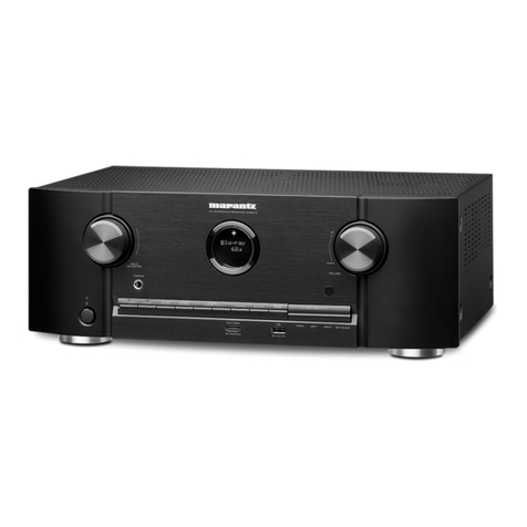
  9. Marantz NR1510 User manual

Marantz NR1510 User manual

Other manuals for NR1510

1

Other Marantz Stereo Receiver manuals

Marantz NR1509 User manual

Marantz

Marantz NR1509 User manual

Marantz SR7200 User manual

Marantz

Marantz SR7200 User manual

Marantz SR6004 Assembly instructions

Marantz

Marantz SR6004 Assembly instructions

Marantz 4270 User manual

Marantz

Marantz 4270 User manual

Marantz SR5008 User manual

Marantz

Marantz SR5008 User manual

Marantz SR6013 User manual

Marantz

Marantz SR6013 User manual

Marantz SR6009/U1B User manual

Marantz

Marantz SR6009/U1B User manual

Marantz CINEMA 70S User manual

Marantz

Marantz CINEMA 70S User manual

Marantz SR7200 User manual

Marantz

Marantz SR7200 User manual

Marantz NR1509 User manual

Marantz

Marantz NR1509 User manual

Marantz SR5002 User manual

Marantz

Marantz SR5002 User manual

Marantz NR1711 User manual

Marantz

Marantz NR1711 User manual

Marantz SR-3001 User manual

Marantz

Marantz SR-3001 User manual

Marantz SR5600 User manual

Marantz

Marantz SR5600 User manual

Marantz SR6004 Quick start guide

Marantz

Marantz SR6004 Quick start guide

Marantz 2250B User manual

Marantz

Marantz 2250B User manual

Marantz SR5011 User manual

Marantz

Marantz SR5011 User manual

Marantz NR1508 User manual

Marantz

Marantz NR1508 User manual

Marantz SR5006 User manual

Marantz

Marantz SR5006 User manual

Marantz SR-63 User manual

Marantz

Marantz SR-63 User manual

Marantz NR1602 User manual

Marantz

Marantz NR1602 User manual

Marantz SR5007 User manual

Marantz

Marantz SR5007 User manual

Marantz SR7002 Assembly instructions

Marantz

Marantz SR7002 Assembly instructions

Marantz NR1603 User manual

Marantz

Marantz NR1603 User manual

Popular Stereo Receiver manuals by other brands

Teac AG-680 Service manual

Teac

Teac AG-680 Service manual

Kenwood KR-V888D instruction manual

Kenwood

Kenwood KR-V888D instruction manual

Teac AGV1050 owner's manual

Teac

Teac AGV1050 owner's manual

Sony STR-435 operating instructions

Sony

Sony STR-435 operating instructions

Pioneer Elite SC-68 Service manual

Pioneer

Pioneer Elite SC-68 Service manual

Pioneer SX-1250 operating instructions

Pioneer

Pioneer SX-1250 operating instructions

Kenwood KMDX92 instruction manual

Kenwood

Kenwood KMDX92 instruction manual

Yamaha RX-830 owner's manual

Yamaha

Yamaha RX-830 owner's manual

Pioneer AVH-Z7250BT owner's manual

Pioneer

Pioneer AVH-Z7250BT owner's manual

Denon AVR-1311 owner's manual

Denon

Denon AVR-1311 owner's manual

Denon AVR-S760H owner's manual

Denon

Denon AVR-S760H owner's manual

Denon AVR-X7200W Service manual

Denon

Denon AVR-X7200W Service manual

Sony XAV-1500 operating instructions

Sony

Sony XAV-1500 operating instructions

Radio Shack DX-399 owner's manual

Radio Shack

Radio Shack DX-399 owner's manual

Sony STR-DE535 - Fm Stereo/fm-am Receiver operating instructions

Sony

Sony STR-DE535 - Fm Stereo/fm-am Receiver operating instructions

Pioneer SX-1000TA operating instructions

Pioneer

Pioneer SX-1000TA operating instructions

Yamaha MusicCast TSR-5B3D owner's manual

Yamaha

Yamaha MusicCast TSR-5B3D owner's manual

Sony STR-DG500 - Multi Channel Av Receiver Service manual

Sony

Sony STR-DG500 - Multi Channel Av Receiver Service manual

manuals.online logo
manuals.online logoBrands
  • About & Mission
  • Contact us
  • Privacy Policy
  • Terms and Conditions

Copyright 2025 Manuals.Online. All Rights Reserved.

AV Surround Receiver
NR1510 Click here!
On-line service parts list
http://dmedia.dmglobal.com/Document/DocumentDetails/25778
ONLINE PARTS LIST (P5)
WEB owner’s manual
NA: http://manuals.marantz.com/NR1510/NA/EN/index.php
EU: http://manuals.marantz.com/NR1510/EU/EN/index.php
AP: http://manuals.marantz.com/NR1510/AP/ZH/index.php
Upload is planned for the time of a future press release.
BEFORE SERVICING THIS UNIT
ELECTRICAL
MECHANICAL
REPAIR INFORMATION
UPDATING
Condential
Ver. 1
Service Manual
•Forpurposesofimprovement,specicationsanddesignaresubjecttochangewithoutnotice.
• Please use this service manual whenreferringtotheoperatinginstructionswithoutfail.
• Some illustrations usedinthisservicemanualareslightlydifferentfromtheactualproduct.
BEFORE SERVICING THIS UNIT
SAFETY PRECAUTIONS
NOTE FOR SCHEMATIC DIAGRAM
HANDLING THE SEMICONDUCTOR AND OPTICS
ONLINE PARTS LIST
Accessing the Parts List
Searching Part Numbers or Ref. Numbers
NOTE FOR PARTS LIST
SERIAL NUMBER
Serial Number Organization
SKU Code of this Unit
POST-SERVICE PRECAUTIONS
Initializing this Unit
JIG FOR SERVICING
Before Servicing
This Unit Electrical Mechanical Repair Information Updating
2
The following items should be checked for continued protection of the customer and the service technician.
Leakage current check
Before returning the set to the customer, be sure to carry out either (1) a leakage current check or (2) a line to chassis resistance check. If the leakage current exceeds 0.5 milliamps, or if the resistance from
chassis to either side of the power cord is less than 460 kohms, the set is defective.
Be sure to test for leakage current with the AC plug in both polarities, in addition, when the set's power is in each state (on, off and standby mode), if applicable.
CAUTION Please heed the following cautions and instructions during servic-
ing and inspection.
◎ Heed the cautions!
Cautions which are delicate in particular for servicing are labeled on the cabinets, the parts and the
chassis, etc. Be sure to heed these cautions and the cautions described in the handling instructions.
◎ Cautions concerning electric shock!
(1) An AC voltage is impressed on this set, so if you touch internal metal parts when the set is energized,
you may get an electric shock. Avoid getting an electric shock, by using an isolating transformer and
wearing gloves when servicing while the set is energized, or by unplugging the power cord when
replacing parts, for example.
(2) There are high voltage parts inside. Handle with extra care when the set is energized.
◎ Caution concerning disassembly and assembly!
Through great care is taken when parts were manufactured from sheet metal, there may be burrs on the
edges of parts. The burrs could cause injury if ngers are moved across them in some rare cases. Wear
gloves to protect your hands.
◎ Use only designated parts!
The set's parts have specic safety properties (re resistance, voltage resistance, etc.). Be sure to use
parts which have the same properties for replacement. The burrs have the same properties. In particular,
for the important safety parts that are indicated by the z mark on schematic diagrams and parts lists,
be sure to use the designated parts.
◎ Be sure to mount parts and arrange the wires as they were originally placed!
For safety seasons, some parts use tapes, tubes or other insulating materials, and some parts are
mounted away from the surface of printed circuit boards. Care should also be taken with the positions
of the wires by arranging them and using clamps to keep them away from heating and high voltage
parts, so be sure to set everything back as it was originally placed.
◎ Make a safety check after servicing!
Check that all screws, parts and wires removed or disconnected when servicing have been put back
in their original positions, check that no serviced parts have deteriorated the area around. Then make
an insulation check on the external metal connectors and between the blades of the power plug. And
otherwise check that safety is ensured.
(Insulation check procedure)
Unplug the power cord from the power outlet, disconnect the antenna, plugs, etc., and on the power.
Using a 500V insulation resistance tester, check that the insulation resistance value between the inplug
and the externally exposed metal parts (antenna terminal, headphones terminal, input terminal, etc.) is
1M Ω or greater. If it is less, the set must be inspected and repaired.
Many of the electric and the structural parts used in the set have special safety properties. In most
cases these properties are difcult to distinguish by sight, and the use of replacement parts with higher
ratings (rated power and withstand voltage) does not necessarily guarantee that safety performance
will be preserved. Parts with safety properties are indicated as shown below on the wiring diagrams and
the parts list in this service manual. Be sure to replace them with the parts which have the designated
part number.
(1) Schematic diagrams Indicated by the z mark.
(2) Parts lists Indicated by the z mark.
The use of parts other than the designated parts could cause electric shocks, res or other dangerous
situations.
CAUTION Concerning important safety parts
SAFETY PRECAUTIONS
Before Servicing
This Unit Electrical Mechanical Repair Information Updating
3
WARNING:
Parts indicated by the z mark have critical characteristics. Use ONLY replacement parts recommended
by the manufacturer.
CAUTION:
Before returning the set to the customer, be sure to carry out either (1) a leakage current check or (2)
a line to chassis resistance check. If the leakage current exceeds 0.5 milliamps, or if the resistance from
chassis to either side of the power cord is less than 460 kohms, the set is defective.
WARNING:
DO NOT return the set to the customer unless the problem is identied and remedied.
NOTICE:
(1) ALL RESISTANCE VALUES IN OHM. k=1,000 OHM / M=1,000,000 OHM
(2) ALL CAPACITANCE VALUES ARE EXPRESSED IN MICRO FARAD, UNLESS OTHERWISE INDICATED. P
INDICATES MICRO-MICRO FARAD. N INDICATES NANO FARAD.
(3) EACH VOLTAGE AND CURRENT ARE MEASURED AT NO SIGNAL INPUT CONDITION.
(4) CIRCUIT AND PARTS ARE SUBJECT TO CHANGE WITHOUT PRIOR NOTICE.
Electrostatic breakdown of the semi-conductors or optical pickup may occur due to a potential differ-
ence caused by electrostatic charge during unpacking or repair work.
1. Ground for Human Body
Be sure to wear a grounding band (1 M ohm) that is properly grounded to remove any static electricity
that may be charged on the body.
2. Ground for Workbench
Be sure to place a conductive sheet or copper plate with proper grounding (1 M ohm) on the workbench
or other surface, where the semi-conductors are to be placed. Because the static electricity charge
on clothing will not escape through the body grounding band, be careful to avoid contacting semi-
conductors with your clothing
<Incorrect>
CBA
Grounding Band
Conductive Sheet or
Copper Plate
1MΩ
1MΩ
<Correct>
CBA
NOTE FOR SCHEMATIC DIAGRAM
HANDLING THE SEMICONDUCTOR AND OPTICS
Before Servicing
This Unit Electrical Mechanical Repair Information Updating
4
ONLINE PARTS LIST
Accessing the Parts List
(1) Access from the Service Manual
・ Click the URL link on the cover of the service manual.
Examples of display
NOTE : If the web browser does not open automatically, copy the URL and paste it into the address bar
of the web browser and then press Enter.
(2) Accessing the Part List from the Model Asset Screen.
・ Display Model Asset from New SDI.
・ Click the section displayed as ▼ Link to Part Lists under the model name.
NOTE : If the ▼ Link to Parts List section is not displayed, download the parts table from the Asset list.
AV Surround Receiver
AAAAAA Click here!
On-line service parts list
http://dmedia.dmglobal.com/Document/DocumentDetails/XXXXX
ONLINE PARTS LIST (P5)
WEB owner’s manual
NA: http://manuals.marantz.com/AAAAA/NA/EN/index.php
EU: http://manuals.marantz.com/AAAAA/EU/EN/index.php
AP: http://manuals.marantz.com/AAAAA/AP/ZH/index.php
Upload is planned for the time of a future press release.
BEFORE SERVICING THIS UNIT
Service Manual Ver. 1
Searching Part Numbers or Ref. Numbers
You can search a Parts List for part numbers or Ref. numbers.
(1) Enter the part number or Ref. number in the search window of the Parts List, and press the search
button.
(2) The search results are displayed.
The name of the sheet in which the search part is used and the part’s line are displayed.
(3) Next, click the "Sheet" section of the search results.
1. Parts indicated by "nsp" on this table cannot be supplied.
2. When ordering a part, make a clear distinction between "1" and "I" (i) to avoid mis-supplying.
3. A part ordered without specifying its part number can not be supplied.
4. Part indicated by "@" mark is not illustrated in the exploded and packaging view.
WARNING: Parts indicated by the z mark have critical characteristics. Use ONLY replacement parts
recommended by the manufacturer.
NOTE FOR PARTS LIST
Before Servicing
This Unit Electrical Mechanical Repair Information Updating
5
Product SKU SKU Code
NR1510/U1B BHU
NR1510/N1B BHV
NR1510/N1SG BHW
NR1510/K1B BHX
SERIAL NUMBER
Serial Number Organization
The 14-digit serial number that contains the code of the manufacturing plant and the manufacturing
date.
SKU
code
14 digits
Factory
code
Cumulative
serial number
Manufactured
Year, month
The last
2digit of year Month
(01 ~ 12)
SKU Code of this Unit
Before Servicing
This Unit Electrical Mechanical Repair Information Updating
6
Make sure to initialize this unit after replacing the microcomputer or any peripheral equipment, or the
digital PCB.
1. Press the power button to turn off the power.
2. While holding down buttons "TUNER PRESET CH +" and "INTERNET RADIO" simultaneously, press the
power button to turn on the power.
3. Release the buttons after conrming that the display ashes at 1-second intervals.
* The unit is initialized.
Use network initialization mode to initialize the network related settings.
NOTE: • If the unit fails to enter the service mode in step 3, repeat the procedure from step 1.
• Initializing the device restores the customized settings to the factory settings. Write down
your settings in advance and recongure the settings after initialization.
Use the following jigs (extension cable kit) when repairing the PCBs.
Order with your dealer for the jigs your dealer if necessary.
8U-110084S : EXTENSION UNIT KIT : 1 Set
(See JIG FOR SERVICING)
INTERNET
RADIO
XTUNER
PRESET +
JIG FOR SERVICING
Initializing this Unit
POST-SERVICE PRECAUTIONS
Before Servicing
This Unit Electrical Mechanical Repair Information Updating
7
ELECTRICAL
SCHEMATIC DIAGRAMS
SCH01 eARC
SCH02 MN864787
SCH03 MN864788
SCH04 ADV7623
SCH05 NET PHY
SCH06 CPU
SCH07 CPU LEVEL CHG
SCH08 DSP
SCH09 DIR A.PLD
SCH10 MAIN DAC
SCH11 D.SUPPLY
SCH12 DIGITAL CNT
SCH13 SPK
SCH14 REG CNT
SCH15 SIDE CNT
SCH16 INPUT
SCH17 VIDEO
SCH18 TUNER
SCH19 F-HDMI
SCH20 FRONT
SCH21 AMP1
SCH22 AMP2
SCH23 SMPS
SCH24 REG
SCH25 FRONT CNT
PRINTED CIRCUIT BOARDS
DIGITAL, F HDMI
AV
SPK, REG CNT, HDMI GUIDE A, HDMI GUIDE
AMP, FRONT, MC HP, USB
REG, GUIDE L, FRONT_FFC GUID, FRONT CNT, SMPS, SIDE CNT
LEVEL DIAGRAM
FRONT ch
CENTER ch
SUBWOOFER ch
SURROUND ch
LEGO ADC
BLOCK DIAGRAM
ANALOG AUDIO DIAGRAM
DIGITAL AUDIO DIAGRAM
VIDEO DIAGRAM
POWER DIAGRAM
WIRING DIAGRAM
SEMICONDUCTORS
1. IC's
2. FL DISPLAY
3. Remote Code Table
Before Servicing
This Unit Electrical Mechanical Repair Information Updating
8
SCHEMATIC DIAGRAMS
SCH01 eARC
VIDEO SIGNAL
CMPONENT(Y)
STBY POWER
ANALOG AUDIO DIGITAL AUDIO
TMDS SIGNAL
GND LINE
POWER- LINE
POWER+ LINE
P0TX0_HPD.
ARC_P
P0TX0_HPD
ARC_N
OPEN-1005C1388
R1145 1K
C1386OPEN-0603
100N-K-0603C2213
EARC_SCLK
EARC_WS R2146 33
EARC_SD0
EARC_SD2
C2212100N-K-0603
100N-K-0603C2208
ARC1.2V
C2214100N-K-0603
10KR2158
10KR2156
R2163 OPEN
HSCL
C2246 2.2U-K-1005
C2242 2.2U-K-1005
6
8
5
7
3
1
4
2
R2227 OPEN
OPENR2157
C2245 2.2U-K-1005
HSDA
ARC_INT
C1385 OPEN-0603
1U-K-1005C1384
D1109
LRB521S-30
EARC_MCLK 33R2084
R2149 33
EARC_SD1
EARC_SD3
2.2U-K-1005C2243
100N-K-0603C2210
2.2U-K-1005C2244
CEC3.3V
R2147 33
100N-K-0603C2211
R2152 33
R2155 1K
EARC_MCLK
EARC_WS
EARC_SD1
EARC_SD3
EARC_MUTE
ARC_RST
DGND
R2148 33
R2153 33
R2154 33
R2160
10K
1000P-K-0603C2247
FROM MN864788
EARC_SCLK
EARC_SPDIF
EARC_SD0
EARC_SD2 TO DIR/A.PLD
FROM CPU
FROM D.SUPPLY
C13871U-K-1005
6
8
5
7
3
1
4
2
33*4(AR)
R2226
U1012
Sil9437CNUC
5
OUT
1
IN
2
GND
3
EN
4
NC
TLV75712PDBVR
U1033
100N-K-0603C2209
L1145 CB05YTYH221-2012
CB05YTYH221-2012L1144
EARC_MUTE
L1149CB05YTYH221-2012
EARC_SPDIF
CB05YTYH221-2012
L1146
L1148CB05YTYH221-2012
eARC
A0 TO 0A
A1
TO 1A
A2
TO 2A
A3
TO 3A
Before Servicing
This Unit Electrical Mechanical Repair Information Updating
9
SCH02 MN864787
VIDEO SIGNAL
CMPONENT(Y)
STBY POWER
ANALOG AUDIO DIGITAL AUDIO
TMDS SIGNAL
GND LINE
POWER- LINE
POWER+ LINE
DA
DA
DA
CK
+5V
R1711
47K
AVDD33RX
VDD33IO
H5V_DET
HPD3 AVDD11RX
VDD33_1
HPD1
HINSELC
AVDD11RX
HINSELB
HINSELA
RX2_5V
RXF_5V
MN864787_HINT
R1882OPEN
RX1_2+
RX1_2-
RX1_1-
RX1_0+
RX1_C-
RXF_2-
RXF_1+
RXF_0-
RXF_0+
LEGOVD23
LEGOVD21 RXF_C-
LEGOVD19
LEGOVD17 C2170
100N-K-0603
LEGOVD15
LEGOVD13
LEGOVD11
LEGOVD9
LEGOVD7
LEGOVD5
LEGOVD3
LEGOVD4
AVDD33TX
PVDD33_1
LEGOVD2 AVDD11TX
LEGOVD0
LEGOHS
LEGOPCK_
C1469 OPEN-1005
C1733 OPEN-3225
D1012 OPEN
D1013 OPEN
RX2_5V
R199147K
MN864787_RST 1KR1976 R188910K
C2338100N-K-0603
LEGOPCK_ 0R1981
C1735 OPEN-3225
TX2_SHLD
TX1+
TX1-
TX0_SHLD
TXC+
TXC_SHLD
CE_REMOTE
DDC_SCK
GND
HP_DET
TX2_SHLD
TX1+
TX1-
TX0_SHLD
TXC+
TXC-
N.C
DDC_SDA
+5V
TX2+
TX2-
TX1_SHLD
TX0+
TX0-
TXC-
N.C
DDC_SDA
+5V
TX1-
CK
HPD
+5V
CK
HPD
R1468 0
R1420 0
R1410 0
R1408
0
RX3_1+
RX3_1-
RX3_C+
RX3_0-
RX3_DDCCL
RX3_5V
RX2_2+
RX2_1+
RX2_1-
RX2_C+
RX2_C-
RX2_DDCDA
RX2_5V
RX1_2+
RX1_2-
RX1_0+
RX1_0-
RX1_C+
RX1_C-
RX1_DDCDA
HPD1
RX1_5V
RXF_1+
RXF_1-
RXF_0+
RXF_0-
RXF_DDCCL
HPD6
CEC_COM
RX5_5V
R1478
2K2
HINSELB
10K
R2031
10KR2028
10KR2033
C2142
100N-K-0603
C2158
100N-K-0603
0R1861
AVDD33TX
AVDD11RX
VDD33_1
VDD11
AVDD33RX
PSDA
MN864787_RST
H5V_DET
DGND
DGND
DGND
TX2+
TX2-
TX0-
TX0+
TX1_SHLD
HDMI_IN3
TXC-
N.C
+5V
DDC_SDA
TX2+
TX2-
TX0+
TX0-
TX1_SHLD
TXC_SHLD
HDMI_IN2
GND
HP_DET
CE_REMOTE
DDC_SCK
TX1+
TX2_SHLD
TX1-
TX0_SHLD
TXC+
TXC_SHLD
HDMI_IN1
GND
HP_DET
CE_REMOTE
DDC_SCK
D1033 OPEN
D1032 OPEN
D1020 OPEN
D1019 OPEN
+5V
CK
HPD
+5V
HPD
10K
R1445
R1444
1K
Q1044
RT1N141C
10K
R1413
R1412
1K
Q1042
RT1N141C
R1404
1K
10K
R1405
DA
Q1046
RT1N141C
R1466 0
R1447
47K
R1451
0
R1421 0
47K
R1415
R1411 0
R1407
47K100N-K-0603
C1536
RX3_2-
RX3_2+
RX3_0+
RX3_DDCDA
RX3_C-
HPD3
RX2_2-
RX2_0-
RX2_0+
RX2_DDCCL
HPD2
RX1_1+
RX1_1-
RX1_DDCCL
RXF_2+
RXF_2-
RXF_C+
RXF_C-
RXF_DDCDA
RXF_5V
RX4_5V
R1479
0
HINSELC
HINSELA
RX3_5V
AVDD33RX
HPD6
R1910
10K
R1908
OPEN
C2016
10U-K-2012(OPEN)
R199610K
C2014
10U-K-2012(OPEN)
HPD2
RX1_5V
C2238
100N-K-0603
100N-K-0603
C2239
RX1_C+
RX1_0-
RX1_1+
100N-K-0603
C2233
100N-K-0603
C2183
RXF_1-
RXF_2+
LEGOVD20
LEGOVD22
100N-K-0603
C2182
RXF_C+
LEGOVD12
LEGOVD14
LEGOVD16
LEGOVD18
C2167
100N-K-0603
LEGOVD6
LEGOVD8
LEGOVD10
82¥Ø -> 0¥Ø
LEGOVS
LEGODE
LEGOVD1
10KR2029
10KR2037
C2139
100N-K-0603
C2140
100N-K-0603
C2141
100N-K-0603
C2144
100N-K-0603
C2145
100N-K-0603
C2148
100N-K-0603
C2152
100N-K-0603
C2153
100N-K-0603
C2155
100N-K-0603
VDD11
6
8
5
7
3
1
4
2
R2196
0
0R1858
0R1864
AVDD11TX
PVDD33_1
R1866
0-2012
4.7U-K-1005C1474 4.7U-K-1005C1483 4.7U-K-1005C1472
L1056
OPEN
C1535 OPEN-1005
C1477 OPEN-1005 C1520 OPEN-1005 C1484 OPEN-1005 C1478 4.7U-K-1005
PSCL
MN864787_HINT
DGND
TO
CPU
DGND
FROM FRONT HDMI
D1008 OPEN
D1007 OPEN
D1011 OPEN
Q1051
RT1N141C
D1014 OPEN
10K
R1608
R1522
1K
100N-K-0603
C1528
R1418
0
100N-K-0603
C1543100N-K-0603
C1534
47K
R1705
R1609
47K
R1709
0
RXF_5V
C1488100N-K-0603
RX1_5V
RX3_5V
R1480
8K2
R1897
1K
R197347K
1N-K-0603C2345
C2017
10U-K-2012(OPEN)
C2015
10U-K-2012(OPEN)
PSDA
PSCL 47R1974
47R1975
C2334
100N-K-0603
R188410K
C2339
100N-K-0603
C2306
100N-K-0603
C2342
100N-K-0603
C2337
100N-K-0603
C2343
100N-K-0603
100N-K-0603
C2184
C2344
100N-K-0603
C2335100N-K-0603
R1989
10K
C2166
100N-K-0603
6
8
5
7
3
1
4
2
0
R2201
6
8
5
7
3
1
4
2
R2197
0
6
8
5
7
3
1
4
2
0
R2200
6
8
5
7
3
1
4
2
0
R2203
4.7U-K-1005C1475 4.7U-K-1005C14934.7U-K-1005C1505
C1506 4.7U-K-1005 C1494 OPEN-1005C1476 OPEN-1005
6
8
5
7
3
1
4
2
R2202
0
C1471 4.7U-K-1005
TX2_SHLD
TX1+
TX0-
TXC_SHLD
CE_REMOTE
DDC_SCK
GND
HP_DET
R1710 0
10KR1950
10KR1972
RX3_DDCDA
RX2_DDCDA
RX3_2-
RX3_1+
C2329100N-K-0603
RX3_0-
RX3_C+
RX2_2+
RX2_2-
RX2_1+
C2317100N-K-0603
RX2_0-
RX2_C+
C2315100N-K-0603
C2314100N-K-0603
OPENR1930
RX1_DDCDA
RXF_DDCDA
LEGOVD17
LEGOVD19
LEGOVD20
LEGOVD21
LEGOVD22
LEGOVD8
LEGOVD10
MN864787_1+
MN864787_1-
MN864787_C+
CB05YTYH221L1052
MN864787_C-
LEGOVD13
LEGOVD14
CB05YTYH221L1053
LEGOVD0
LEGOVD2
LEGOVD5
LEGOVD7
LEGOVS
LEGODE
OPENL1055
VDD33IO
RX4_5V
CEC_COM
MN864787_2+
MN864787_1+
MN864787_0+
MN864787_0-
MN864787_C+
R2099 0-3216
CEC3.3V
CEC1.1V
D1035 OPEN
D1034 OPEN
D1022 OPEN
D1021 OPEN
TX2+
TX2-
TX0+
TX1_SHLD
N.C
TXC-
TX0_SHLD
TXC+
+5V
DDC_SDA
RT1N441C
Q1048
R1455
47K
D1031
OPEN
47K
R1446
RT1N441C
Q1045
R1419
47K
47K
R1414
RT1N441C
Q1043
R1409
47K
47K
R1406
R1521 0
RT1N441C
Q1047
MN864787
10K
R1951
R1893
1M
C205210P-J-1005
4
21
3
27MHz(FA-238,7P)
X1007
RX2_DDCCL
RX3_DDCCL
C2333100N-K-0603
C2331100N-K-0603
C2332100N-K-0603
RX3_0+
RX3_1-
RX3_2+
C2330100N-K-0603
RX3_C-
C2326100N-K-0603
C2328100N-K-0603
RX2_0+
RX2_1-
C2316100N-K-0603
C2324100N-K-0603
RX2_C-
10KR1898
RXF_DDCCL
RX1_DDCCL
100N-K-0603C2313
C2186
100N-K-0603
100N-K-0603
C2270
LEGOVD16
LEGOVD18
LEGOVD9
LEGOVD23
LEGOVD11
CB05YTYH221L1050
OPEN
L1054
CB05YTYH221
L1072
MN864787_2+
MN864787_2-
MN864787_0+
MN864787_0-
LEGOVD1
LEGOVD12
LEGOVD15
CB05YTYH221L1049
LEGOVD3
LEGOVD4
CB05YTYH221L1051
LEGOVD6
LEGOHS
L1071
CB05YTYH221
RX5_5V
TO
MN864788
MN864787_1-
MN864787_2-
MN864787_C-
R2094 0-3216
STBY5V
D1009 OPEN
D1010 OPEN
FROM
CPU LEVEL CHG
C2055 9P-D-1005
100N-K-0603
C2310
C2336
100N-K-0603
FROM
NET PHY
C2173
100N-K-0603
FROM
D.SUPPLY
191715131198765432 18161412101
N1014
A111989-A-01-T W/O FLNG
191715131198765432 18161412101
N1015
A111989-A-01-T FLNG
191715131198765432 18161412101
N1016
A111989-A-01-T FLNG
191715131198765432 18161412101
N1017
A111989-A-01-T FLNG
1011
12
1314
15
16
54321 6
9
87
U1025
SN74CBT3251PW
GND
VCC
B5
B6
B7
B8
S0
S1
S2
B4
B3
B2
B1
A
NC
OE
216
215
214
212
210
208
206
204
202
200
198
197
196
195
194
193
191
189
187
185
183
181
179
177
176
175
174
173
172
170
168
166
164
1 3 5 76 98 1110 12 14 16 18 20 22 24 26 28 3029 31 33 35
209
211
213
203
201
207
205
199
192
186
188
190
182
180
178
184
171
163
169
165
167
162160158156154153152151149147145143141139137135133132130128
37
126
39
124
41
122
43
120
45
118
47
116
49
114
50 51
112113
52 53
111
54
109
2 4 13 15 17 19 21 23 25 3227 34 36
73
75
76
77
78
79
80
82
84
86
88
90
92
94
95
96
97
98
99
100
101
103
105
107
161157155159146148150138140142144131134136
38 40
123125127129
42 44 46 48
115117119121
74
81
83
85
87
89
91
93
102
104
106
108
110
55
56
57
58
59
61
63
65
67
69
71
60
62
64
66
68
70
72
217
IC1024
MN864787
VSS
Q0
Q2
Q5
Q6
Q8
Q10
Q9
Q11
Q13
Q12
Q14
Q15
Q17
Q18
Q21
Q23
VSS
D22
D23
DEIN
VSS
VSS
Q4
Q3
Q1
Q7
Q16
VSS
Q22
Q20
Q19
VDD11
D0RX0SCL
D2RX1SCL
D4
VSS
D5
VSSCH1ASPDIF
VDD33
D6
CH1ALRCLK
CH1ABCLK
D7
D8NOSDIRQ
CH1ASD0
D9VDD11
D11P0RX2P
AVDD11RX0
P0RX1M
P0RX0P
AVDD11RX0
P0RXCM
VSS
AVDD33RX0
P1RX2M
P1RX2P
VSS
P1RX1P
AVDD11RX1
AVDD11RX1
P1RX1M
P1RX0P
AVDD11RX1
P1RXCM
VSS
NCS
VSSMOSI
D12VDD33
D13
D14NIRQA1
NIRQA0
D15
D16RX2SDA
RX2SCL
D17
D18
D19
VSS
VSS
VDD11
VDD11
AVDD11TX
P1TX1P
P1TX1M
AVDD33TX
P1TX0M
P1TXCP
AVDD11TX
P1TXCM
VDD11
P0TX2P
AVDD11TX
P0TX2M
AVDD11TX
P0TX0P
P0TX0M
AVDD11TX
TX1SCL
TX1SDA
VDD33
VDD33IO
VDD33IO
VDD33IO
PCLKOUT
VDD33IO
VDD11
DEOUT
NC/XO
SYSCLK/XI
HSDA0
215.TX1HPD
167.NRESET
164.TX0ARCIN
165.NTEST
163.TX1ARCIN
56.D21
VSYNCIN
CH0ASPDIF
CH0ABCLK
PVDD33
AVDD33RX3
P3RXCP
P3RX0M
P3RX0P
AVDD11RX3
P3RX1M
P3RX1P
AVDD11RX3
P3RX2M
P3RX2P
AVDD33RX2
P2RXCP
P2RX0M
AVDD11RX2
P2RX1P
P2RX2M
P2RX2P
NIRQ1
VDD11
CH0ASD2
CH0ASD3
CH0ASD0
CH0ASD1
CH0ALRCLK
HSCL1
VDD33
RX2P5V
VDD11
PCLKIN
VDD11
CEC0
VDD33
D1
D3
216.TX0SCL
RX1SDA
RX0SDA
166.HSCL0
D10
VSS
VSS
P0RX2M
P0RXCP
P0RX0M
AVDD11RX0
P0RX1P
VSS
AVDD33RX1
P1RXCP
P1RX0M
SCLK
MISO
VDD11
55.D20
HSYNCIN
VDD33
CH0AMCLK
VDD11
P3RXCM
AVDD11RX3
P2RXCM
AVDD11RX2
P2RX0P
P2RX1M
AVDD11RX2
NIRQ0
HSDA1
RX3P5V
RX1P5V
P1TX2P
P1TX2M
AVDD11TX
P1TX0P
P0TX1P
AVDD33TX
P0TXCP
P0TXCM
VDD11
VSYNCOUT
HSYNCOUT
109.RX0P5V
110.RX3SDA
111.RX3SCL
1.TX0SDA
2.TX0HPD
P0TX1M
A4
TO 4A
A5
TO 5A
A6
TO 6A
A7
TO 7A
A8
TO 8A
A9
TO 9A
N1014
TO JK202
Before Servicing
This Unit Electrical Mechanical Repair Information Updating
10