Denon Professional DN-508MXA User manual

User Guide English ( 3 – 16 )
Guía del usuario Español ( 17 – 30 )
Guide d’utilisation Français ( 31 – 44 )
Guida per l’uso Italiano ( 45 – 58 )
Benutzerhandbuch Deutsch ( 59 – 72 )
A
ppendix English ( 73 – 75 )
DN-508MXA


3
User Guide (English)
Introduction
DN-508MXA is a professional 8-zone mixer and 4-zone amplifier with remote controllability via
RS-232C, RS-422, and IP. It has professional-grade audio circuitry, mic/line pad functions, full
BTL (bridge-tied load) balanced outputs, 3-band input equalization, 5-band output
equalization, priority, delay, dynamics, LoZ and HiZ speaker support, and an automatic power-
saving function. When connected to a network or router, you can use a web-based interface
to control the system, as well.
Please see this guide’s Setup chapter to learn how to integrate DN-508MXA with your audio
system, and then refer to the Operation chapter to start using DN-508MXA.
Box Contents
DN-508MXA
Euroblock Connectors
(6) 5-Pin (for the Line Outputs 1–8 and Amp Inputs 1–4)
(2) 4-Pin (for Mic/Line Inputs 1 & 2)
(4) 3-Pin (for Mic/Line Inputs 3–6)
(5) 2-Pin (for the Speaker Outputs 1–4 and Mute connector)
(2) 5-Pin with Jumper Wires (for connecting Line Output 1–4 and Amp Inputs 1–4)
Power Cable
User Guide
Safety & Warranty Manual
Support
For the latest information about this product (system requirements, compatibility information,
etc.) and product registration, visit denonpro.com.

4
Features
Front Panel
1. Power Button: Press this button to power DN-508MXA on or off.
2. Display: This screen indicates the current settings, status, etc.
3. Volume/Sel: Turn the knob to navigate or scroll through the options shown in the display, and then
press the knob to select one.
4. Menu: Press this button to switch between the Menu and the settings of the current zone in the display.
In the Menu, turn the Volume/Sel knob to navigate or scroll through the available options, and then
press the knob to select it.
5. Mute/Back: When viewing the settings of the current zone, press this button to select the Mute setting.
To mute or unmute the zone, turn the Volume/Sel knob to select Mute or Unmute, and then press it to
confirm your choice.
When in the Menu, press this button to return to the previous screen.
6. Aux In (1/8” /3.5 mm):Use a standard stereo 1/8” (3.5 mm) cable to connect an optional audio source
to this stereo input. When a cable is connected to this input, the Aux In (RCA) inputs on the rear panel
will be disabled.
7. Mic/Line Indicators: These lights will illuminate different colors to show the signal status of each
mic/line input:
•Off: The input is receiving no signal or a very low-level signal.
•Green: The input is receiving a signal at an optimal level.
•Amber: The input’s signal is very high.
•Red: The input’s signal is “peaking” (higher than 0 dB). Decrease its Gain knob on the rear panel
or decrease the volume of the source to prevent “clipping” (distortion).
8. Source Indicators: These lights will illuminate different colors to show the signal status of the aux in
and ST inputs:
•Off: The input is receiving no signal or a very low-level signal.
•Green: The input is receiving a signal at an optimal level.
•Amber: The input’s signal is very high.
•Red: The input’s signal is “peaking” (higher than 0 dB). Decrease the volume of the source to
prevent “clipping” (distortion).
9. Source Selectors: Press one of these buttons to assign or unassign that source to the currently
selected zone. When a source is assigned to the zone, its button will be lit amber. To select a zone,
press one of the Output Selectors.
10. Output Indicators: These lights will illuminate different colors to show the signal status of the line
outputs (zone outputs):
•Off: The output is sending no signal or a very low-level signal.
•Green: The output is sending a signal at an optimal level.
•Amber: The output’s signal is very high.
•Red: The output’s signal is “peaking” (higher than 0 dB). Decrease the volume of the zone to
prevent “clipping” (distortion).
11. Output Selectors: Press one of these buttons to select that zone. The button for the currently selected
zone will be lit amber.
12. Protection Indicator: These red LEDs will light when amplifier protection is engaged for the Speaker
Outputs. The LEDs correspond to Zones 1-4.
DN-508
MXA
PROTECTION
123
4
5
6
8
9
10
11
12
7
DVD
CD
Dining
Room L
Dance
Hall L
Kitchen
Dance
Hall R
Dining
Room R
Phone

5
Rear Panel
1. Power Input: Use the included power cable to connect this input to a power outlet.
2. Line Outputs: Use Euroblock connectors to connect these line-level outputs to your
loudspeakers or other audio devices. Each group of 5 connections corresponds to 2 zones.
Each zone has a hot (H) and cold (C) connector, and each pair of zones shares the ground (G)
connector. Make sure each loudspeaker is connected to the desired zone.
To send audio signal to the Speaker Outputs, use the included 5-pin Euroblock with jumper wires
to connect the Line Outputs of Zones 1-4 to the Amp Inputs of Zones 1-4.
3. Mic/Line Inputs: Use Euroblock connectors to connect your mic-level or line-level audio
sources to these inputs. Each input has a hot (H), cold (C), and ground (G) connector. Inputs 1
and 2 have an additional connector for Page Switch. Remember to adjust the Gain knob to set
the input volume level.
4. Mic/Line Gain: Turn these knobs to set the input gain for each Mic/Line Input.
5. Aux In (RCA):Use a standard stereo RCA cable to connect an optional audio source to this
stereo input. When a cable is connected to the Aux In on the front panel, these inputs will be
disabled.
6. ST Inputs: Use standard stereo RCA cables to connect line-level audio sources to these inputs.
7. Mute Connector: Use a 2-pin Euroblock connector to attach a switch to this connector. The
switch can then mute or unmute the incoming signal from all audio sources.
8. Remote Port: This port lets you connect a computer to DN-508MXA. Use a 9-pin D-Sub cable
to make this connection. You can use the computer with a third-party utility to manage DN-
508MXA via serial communication.
9. Remote Extend Port: This port lets you connect another DN-508MXA to the host device. Use a
9-pin D-Sub cable to make this connection. You can use a computer with a third-party utility to
control all connected DN-508MXA units via serial communication.
10. RS-422 Port: This port lets you connect a host device to DN-508MXA. You can then use a third-
party utility to control DN-508MXA via serial communication. Use a standard analog telephone
cable with RJ45 connectors to make this connection.
11. Ethernet Port: This port lets you connect DN-508MXA to a network. Connect this port to a
computer via a network switch or router. Alternatively, connect it directly to a computer using an
Ethernet crossover cable. This connection lets you control DN-508MXA though the web
interface.
12. Speaker Output: Use Euroblock connectors to connect these outputs to your loudspeakers at
low-impedence (LoZ), high-impedence (HiZ) or BTL (bridge-tied load). When using LoZ, each
group of 2 connections corresponds to 1 zone, for 4 total zones. When using HiZ and BTL, each
pair of groups of 2 connections corresponds to 1 zone, for 2 total zones. Each zone has a
positive (+) and negative (-) connector. Make sure each loudspeaker is connected to the desired
zone and that the wiring polarity is correct.
13. Amplifier Input: Use Euroblock connectors to connect line-level audio sources to these inputs.
Each zone has a hot (H) and cold (C) connector, and each pair of zones shares the ground (G)
connector.
To send audio signal to the Speaker Outputs, use the included 5-pin Euroblock with jumper
wires to connect the Line Outputs of Zones 1-4 to the Amp Inputs of Zone 1-4.
14. Fan: The speed of the fan adjusts automatically to cool the unit.
1
23
4
56
8
10
11
7
9
12
13
14

6
Setup
Items not listed under Introduction > Box Contents are sold separately.
To set up DN-508MXA with your sound system:
1. If you are using any audio source with RCA outputs (Blu-ray®players, stereos, etc.), use standard RCA
cables to connect them to the ST inputs on the rear panel. Your audio sources must be line-level (no
phono-level turntables).
2. If you are using an amplifier or other audio source with outputs that can be wired into standard
Euroblock connectors, connect them to the Mic/Line Inputs on the rear panel.
3. Use the included 5-pin Euroblock with jumper wires to connect Line Outputs 1–4 to Amp Inputs 1–4.
Each group of 5 connections corresponds to 2 zones. Each zone has a hot (H) and cold (C) connector,
and each pair of zones shares the ground (G) connector.
4. Use standard Euroblock connectors to connect the loudspeakers of your different zones to the
Speaker Outputs on the rear panel. For LoZ speakers at 4 Ohm or 8 Ohm, each group of 2
connections corresponds to 1 zone, for 4 total output zones. For HiZ speakers at 70 V, 100 V, or BTL,
each pair of groups of 2 connections corresponds to 1 zone, for 2 total zones. Each zone has a positive
(+) and negative (-) connector. Always make sure to properly align the wiring polarities between your
speakers and DN-508MXA.
5. To manage DN-508MXA using its web interface, connect the Ethernet Port and your computer to a
network switch or router using standard Ethernet cables. If your computer is wirelessly connected to
your router, connect just DN-508MXA to that router. Alternatively, connect DN-508MXA’s Ethernet Port
directly to a computer using an Ethernet crossover cable.
6. To manage DN-508MXA using serial communication, connect the remote port to your computer
using a 9-pin D-Sub cable. Use a third-party utility to manage DN-508MXA. Alternatively, connect the
RS-422 port to a third-party utility using a standard analog telephone cable with RJ45 connectors.
Tip: We recommend using the web interface to control DN-508MXA rather than serial communication. It
is much easier to use the web interface via IP communication than a third-party utility via RS-232 serial
communication.
7. Use the included power cable to connect DN-508MXA to a power outlet.
8. Power on all of your audio sources (Blu-ray®players, stereos, microphones, amplifiers, etc.).
9. Power on DN-508MXA.
Example:
Zone 1
Zone 2 Zone 3
Zone 4
Computer
To Zone Speakers
Blu-ray Player
Amplifier
Router
Microphones Power
Jumper Wires
(Connects Line
Outputs 1–4 to
Amp Inputs 1–4)

7
Operation
After setting up and powering on DN-508MXA and your connected devices, you can start using DN-
508MXA.
Important: The default administrator password is adminpwd. There is no default operator password.
Using the LCD Interface
Navigating the Display and Menus
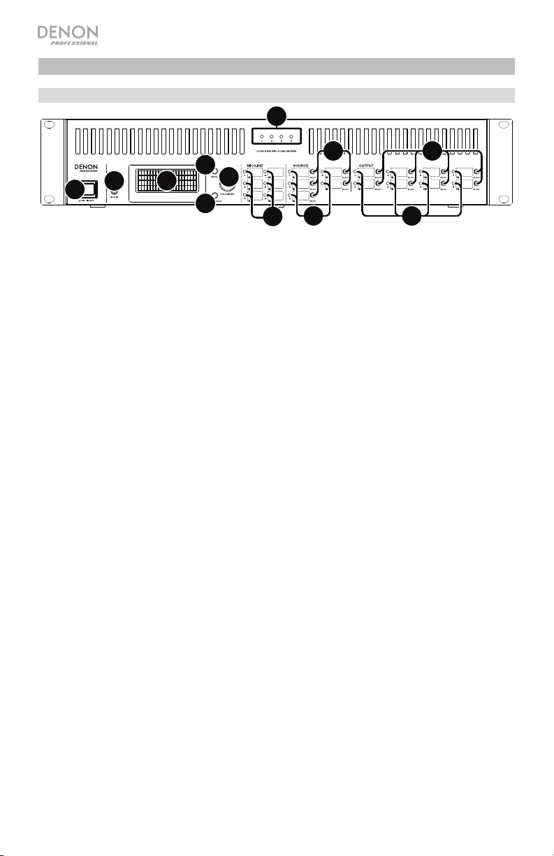
To switch between the Menu and the settings of the current zone, press Menu.
To move through the options in the display, turn the Volume/Sel knob.
To select an option in the display, press the Volume/Sel knob.
To return to the previous screen, press Mute/Back.
To lock all controls, press and hold the Menu button for 3 seconds. Turn the Volume/Sel knob to select
Yes or No when prompted to “Apply to change?” the LOCK setting. You will need to enter the administrator
password to successfully lock all controls. To unlock all controls, press and hold the Menu button for 3
seconds again. Turn the Volume/Sel knob to select Yes or No when prompted to “Apply to change?” the
UNLOCK setting. You will need to enter the administrator password to successfully unlock all controls.
Managing Zones
To select a zone, press the desired output selector. The currently selected one will be lit amber. The
source selectors of any audio sources that are assigned to that zone will light up amber, as well.
To assign or unassign an audio source to a zone, press the desired output selector, and then press the
desired source selector. The source selector for the currently assigned audio source will be lit amber. Only
one source can be assigned to a zone at a time.
To set the volume level of a zone, press the desired output selector, and then turn the Volume/Sel knob.
To mute a zone, press the desired output selector, and then press the Mute/Back button. Turn the
Volume/Sel knob to select whether to Mute or Unmute the channel, and then press the knob to select it.
Menu
Click the Menu button and select Preset, System, or Information to view the corresponding settings page.
1. Preset
Mic/Line: Select this to edit Mic/Line Source 1–6. Once selected, you can set the frequency (Freq), Gain, or
bandwidth (Q) of the 3 available equalizations: a low-shelving filter (SHL), a high-shelving filter (SHH), and a
parametric equalizer (PEQ). Only the parametric equalizer has a bandwidth control. You can also set the
Input Volume that each Mic/Line Input sends to each Zone.
Source: Select this to edit Source 1–4 or Aux. Once selected, you can set the frequency (Freq), Gain, or
bandwidth (Q) of the 3 available equalizations: a low-shelving filter (SHL), a high-shelving filter (SHH), and a
parametric equalizer (PEQ). Only the parametric equalizer has a bandwidth control.
Output: Select this to edit Zone 1–8.
•Source Select: Select this to choose Source 1–4 or Aux. You can use the Volume/Sel knob to select
a source, or press the source selectors.
•Source Level: Select this to set the input level of the selected source.
•Source Mute: Select this to turn source mute on or off.
•Mic Level: Select this to set the output level of the microphone.
•PEQ: Set the frequency (Freq), Gain, or bandwidth (Q) of the 5 frequency ranges: Low, Mid-Low,
Mid, Mid-High, and High.
•Master Level: Select this to set the zone’s overall output level.
Note: If a zone is stereo, it will actually use 2 zones (e.g. Zone 1-2, 3-4) that share the same output
settings. The second zone of a stereo pair (e.g. Zone 2 or 4) will show as unavailable for editing. You
can edit the first zone, or change the Zone’s settings in the Output menu.

8
2. System
Schedule: Select a Schedule 1–30 to edit. To edit a Schedule, you may have to enter the
administrator password.
•On/Off: Select this to enable or disable the schedule. You can use multiple schedules
simultaneously.
•Date: Select this to set a specific date on which to apply the schedule (instead of regular days
of the week). Click each menu to select the Month, Day, and Year. You can also set the
schedule to repeat every month, day, and/or year.
•Day of Week: Select this option to apply the schedule regularly to certain days of the week
(instead of a specific date). Select each day to turn it on or off.
•Time: Select this option to set the Hour and Minute when the schedule will be applied. You
can also set the schedule to repeat every hour.
•Command: This field will show any serial commands assigned to the Schedule. Serial
commands can be added or changed using Web Remote.
Mic/Line: Select a Mic/Line 1–6 to edit.
•Name: Select this to edit the display name of the Mic/Line channel, up to 32 characters.
•Mic/Line: Select this to set the input level for a microphone (Mic) or a line-level device (Line).
•Hi pass filter: Select this to turn the high-pass filter on or off.
•Phantom: Select this to turn phantom power on or off. Please note that most dynamic
microphones do not require phantom power, while most condenser microphones do. Consult
your microphone’s documentation to find out whether it needs phantom power.
Source: Select a Source 1–4, Aux, or Aux AGC to edit.
•Name: Select this to edit the display name of the Source up to 32 characters.
•Gain: Select this to set the gain trim level of each audio source.
•Aux AGC: These settings control the automatic gain control (AGC), which adjusts the gain level
to help reduce noise in the signal.
oCompensation Level: Select this to set how much gain is applied after the signal is
compressed by the AGC.
oResponse Time: Select this to set how quickly the AGC reacts to audio signal.
oNoise Gate: Select this to enable (On) or disable (Off) the noise gate. When on, the audio
signal will be automatically muted if it is below a certain volume level. This eliminates
moments during which the source is not producing any sound but there is still detectable
noise in the audio signal.
Output: Select a Zone 1–8 to edit.
•Name: Select this to edit the display name of the Zone Output up to 32 characters.
•Mono/Stereo: Select this to set whether the audio signal the zone plays is monaural (Mono) or
binaural (Stereo). When set to Stereo it will actually use 2 zones (e.g., Zones 1–2, Zones 3–4),
which will share the same output settings.
Note: When using a Stereo output, editing the first zone will apply changes to both zones. The
second zone will show as unavailable for editing.
•Priority Settings: Each zone has settings for 1st priority and 2nd priority. When the mic/line
input (set in the Source menu) detects an incoming audio signal, any other signal sent to that
zone will be attenuated (“ducked”) so the incoming signal can be heard. The 1st-priority source
will attenuate the 2nd-priority source.
oVolume: Select this to set the volume level of the incoming audio signal.
oSource: Select this to set the source for the priority: Mic/Line 1–6or no source (None).
Setting both priorities to the same mic/line input will result in greater-than-normal
attenuation.
oThreshold: Select this to set the threshold. The incoming audio signal must be louder than
this threshold to attenuate the current signal. A lower threshold produces more attenuation.
oAttack Time: Select this to set how long it takes for the current signal to be fully attenuated.

9
oHold Time: Select this to set how long the current signal remains fully attenuated after the
incoming audio falls below the threshold.
oRelease: Select this to set how long it takes from the fully attenuated signal to return to its
previous level after the incoming audio signal falls below the threshold.
oAttenuation Level: Select this to set how much the current signal’s volume is attenuated
(“ducked”).
•Delay: Select this to set how long it takes for the zone to play any incoming audio signal after it
receives it. This is useful when multiple zones are playing the same audio signal—listeners in
certain areas may hear that same signal multiple times because the sound from each zone
reaches them at different times rather than all at once. Delaying the zone’s audio output can
help prevent this effect.
•Dynamics: These settings determine the dynamic control (via compression) of the zone’s
output signal.
oOn/Off: Select this to enable (On) or disable (Off) the zone’s dynamic control.
oThreshold: Select this to set the threshold. The incoming audio signal must be louder than
this threshold to trigger the dynamic control.
oRatio: Select this to set the ratio of the dynamic control—how much the signal is attenuated
relative to its original level.
oAttack Time: Select this to set how long it takes for the dynamic control to compress the
signal.
oRelease: Select this to set how long it takes from the compressed signal to return to its
original level after the incoming audio signal falls below the threshold.
oGain: Select this to set how much gain is applied after the signal is compressed.
oKnee: Select this to set the knee of the dynamic control. This determines how sharp or
smooth the “curve” is when compression is applied at the threshold. A “hard” knee
produces very dramatic compression, while a “soft” knee produces a more natural-sounding
compression.
Amp: Select this to edit the Amp Inputs 1–4. Once selected, you can set Hi Impedance Mode (70V
mode, 100V mode, or Off), Hi Pass Filter (On or Off), BTL (On or Off), and Impedance Mode (4 ohm
or 8 ohm).
Mute: Select this to mute either the music only (Music) or all audio signals (All).
Ethernet: Select this to configure your Ethernet settings. Select IP Address, Subnet Mask, Gateway, or
IP Control Port to configure DN-508MXA to detect network settings automatically (Auto On/Off), or enter
settings manually using the Volume/Sel knob.
Baudrate: Select this to set the baud rate of each port. RS232C is for the remote port. RS422 is for
the RS-422 port. Each rate is shown bits per second (BPS).
Time: Select this to edit the System Time and set the current month, day, year, hour, minute, and
second. DN-508MXA will display this at the top of the web interface and will use it for scheduling.
You can also set DN-508MXA to enable (On) or disable (Off) daylight saving time. When on, select
each menu below it to set the month, day, and hour that daylight saving will start and end. Choose
Offset to select how much the time will be shifted.
Passwords: Use these fields to set a new password for the administrator (Admin), which can control
all DN-508MXA functions, or the operator (Operator), which can control only certain functions.
3. Information
Firmware Version: This field shows the current firmware version installed in DN-508MXA.
Important: Visit denonpro.com to download the latest firmware for DN-508MXA.
Network Information: Select this to view the current settings for IP Address, Mac Address,
Gateway, and DNS.

10
Using the Web Interface
Important: To use the web interface, both DN-508MXA and your computer must be
connected to the same network. We recommend connecting the Ethernet Port and your
computer to a network switch or router using standard Ethernet cables. If your computer is
wirelessly connected to your router, connect just DN-508MXA to that router. Alternatively,
connect DN-508MXA’s Ethernet Port directly to a computer using an Ethernet crossover
cable.
To open the DN-508MXA web interface, on your computer, open a web browser.
•If DN-508MXA is connected directly to a computer, go to http://192.168.0.1 in your web
browser. You may have to enter the operator password. There is no default password,
but if you have already set one, you will have to enter it here.
•If DN-508MXA is connected to a network switch or router (wirelessly or wired), use the
Menu button and the Volume/Sel knob to do the following:
i. Press Menu to enter the Menu.
ii. Select and enter 2. System, then Ethernet, then IP Address, and then the Auto
setting (you may have to enter the administrator password).
iii. Set Auto to On, and select Yes when asked if you want to apply the change.
iv. Press the Mute/Back button to return to the previous page, and then select IP
Address again. The display will now show a maximum 12-digit IP address. Enter this
address into your web browser as http://###.###.###.###. You may have to enter the
administrator password. The default administrator password is adminpwd.
To use the controls shown in the web interface:
•Pages: Click the Output, Input, or Settings button at the top of the window to view each
page in the web interface below.
•Faders: Click and drag a fader to set its level. Alternatively, click the dB field below it,
enter a value with your computer keyboard, and then click elsewhere in the page.
•Menus: Click a menu, and then click an option to select it.
•Buttons: Click a button to select it.
•Checkbox: Click a checkbox to select or deselect it.
•Text Field: Click a text field, enter a name with your computer keyboard, and then click
elsewhere on the page.
Important: In order to make changes in the web interface, first click the lock icon at the top of
the page. You will need to enter the Administrative password to unlock the page to make
changes. The default Admin password is adminpwd. Once you have finished editing, you can
lock the page again to prevent further changes.

11
Output
Click the Output button at the top
to view the Output page where you
can set the levels, equalization,
inputs, and mute status of each
zone.
If a zone is stereo, it will actually
use 2 zones (e.g., Zones 1–2,
Zones 3–4), which will share the
same output settings. If a zone is
mono, it will use one zone only.
Protection Indicator: These red
LEDs will light when amplifier
protection is engaged for the
Speaker Outputs. The LEDs
correspond to Zones 1-4.
Input Menu: Click this menu to
select which source is sent to the
zone.
Signal: This light indicates that the zone is sending out an audio signal.
Peak: This light indicates that the zone is sending out an audio signal that is “peaking”
(exceeding 0 dB). If this happens, lower the level of the Source or Mic/Line fader.
Mute: Click this button to mute or unmute the source. The button will be highlighted when
muted.
Input: Click this button to open the Zone Input window. In this window, click and drag each
fader to set the audio signal level that each Mic/Line Input sends specifically to that zone.
(This does not affect the levels that those inputs send to other zones.)
EQ: Click this button to open the Zone EQ window. In this window, click each menu to set the
frequency (Freq), Gain, or bandwidth (Q) of the 5 frequency ranges: Low, Mid-Low, Mid, Mid-
High, and High.
Source: Click and drag this fader to set the input level of the source you selected in the Input
Menu (described above).
Mic/Line: Click and drag this fader to set the overall level of the Mic/Line Inputs. This setting
is applied in addition to the settings in the Zone Input window (described above).
Master: Click and drag this fader to set the zone’s overall output level.
To Zone 5-8 / To Zone 1-4: Click either of these buttons to jump to the lower or upper half of
the page, respectively.

12
Input
Click the Input button at the top to view the Input page where you can set the equalization or output
level of each input (the Mic/Line Inputs, ST Inputs, or Aux In).
Signal: This light indicates that the input is receiving an audio signal.
Peak: This light indicates that the input is receiving an audio signal that is “peaking” (exceeding 0
dB). If this happens, reduce the setting of the Mic/Line Gain knob on the rear panel (for Mic 1–6) or
on the audio source itself (for Source 1–4and Aux).
EQ: Click this button to open the Input EQ window. In this window, click each menu to set the
frequency (Freq), Gain, or bandwidth (Q) of the 3 available equalizations: a low-shelving filter (SHL),
a high-shelving filter (SHH), and a parametric equalizer (PEQ). Only the parametric equalizer has a
bandwidth control.
Output: Click this button to open the Mic Output window. In this window, click and drag each fader
to set the audio signal level that each mic/line channel sends specifically to each zone.
Settings
Click the Settings button at the top and select Schedule, I/OName, or System to view the
corresponding settings page.
Important: Click the lock icon at the top of the page to lock or unlock the settings. When locked, you
cannot edit any of the settings. This is helpful to prevent any accidental changes to the overall operation.
Schedule
Schedule: Click this menu to select a schedule to
view.
•On/Off: Click one of these buttons to enable or
disable the schedule. You can use multiple
schedules simultaneously.
•Date: Click this menu to set a specific date on
which to apply the schedule (instead of regular
days of the week). Click each menu to select the
Month, Day, and Year. The ** option sets the
schedule to repeat every month, day, or year.
•Day of Week: Click this menu to apply the
schedule regularly to certain days of the week
(instead of a specific date). Click each checkbox
to select or deselect the day.
•Time: Click each menu (Hour and Minute) to set
when the schedule will be applied. The ** option
sets the schedule to repeat every hour.
•Restore: Click this menu to reset all changes
you have made to the current schedule.
•Save: Click this menu to save the currently shown schedule.

13
I/O Name
This window shows the names of all of your
inputs (Mic/Line Inputs, ST Inputs, and Aux
In) and zone (Line Outputs). Click each field
and enter a name using your computer
keyboard. Click Save to save the names.
System
•Setting File: This field shows the
currently loaded setting file, if any. To
download the current setting file (if any)
to your computer, click Download. To
upload a setting file from your computer
to DN-508MXA, click Browse, find and
select the file, and then click Upload.
•Mic/Line: For each mic/line input,
select whether the input is a
microphone (Mic) or a line-level device
(Line), whether the high-pass filter
should be enabled (On) or disabled
(Off), and whether the microphone
should receive phantom power (On) or
not (Off). Please note that most
dynamic microphones do not require
phantom power, while most condenser
microphones do. Consult your
microphone’s documentation to find
out whether it needs phantom power.
•Source: Click each Gain menu to set
the gain trim level of each audio source.
All sources have an editable automatic
gain control (AGC), which adjusts the
gain level to help reduce noise in the
signal:
oCompensation Level: Click this
menu to set how much gain is
applied after the signal is
compressed by the AGC.
oResponse Time: Click this menu to
set how quickly the AGC reacts to
audio signal.
oNoise Gate: Click one of the
buttons to enable (On) or disable
(Off) the noise gate. When on, the
audio signal will be automatically
muted if it is below a certain volume
level. This eliminates moments
during which the source is not
producing any sound but there is
still detectable noise in the audio
signal.

14
•Output: Use these settings to determine how
each zone manages its audio output.
oZone Mono/Stereo: Click this menu to set
whether the audio signal the zone plays is
monaural (Mono) or binaural (Stereo). When
set to Stereo it will actually use 2 zones (e.g.,
Zones 1–2, Zones 3–4), which will share the
same output settings.
oPriority Settings: Each zone has settings for
1st priority and 2nd priority. When the Mic/Line
Input (set in the Source menu) detects an
incoming audio signal, any other signal sent to
that zone will be attenuated (“ducked”) so the
incoming signal can be heard. The 1st-priority
source will attenuate the 2nd-priority source.
Volume: Click this menu to set the volume
level of the incoming audio signal.
Source: Click this menu to set the source
for the priority: Mic/Line 1–6or no source
(None). Setting both priorities to the same
mic/line input will result in greater-than-
normal attenuation.
Threshold: Click this menu to set the
threshold. The incoming audio signal must
be louder than this threshold to attenuate
the current signal. A lower threshold
produces more attenuation.
Attack Time: Click this menu to set how
long it takes for the current signal to be fully
attenuated.
Hold Time: Click this menu to set how long
the current signal remains fully attenuated after the incoming audio falls below the threshold.
Release: Click this menu to set how long it takes from the fully attenuated signal to return to its
previous level after the incoming audio signal falls below the threshold.
Attenuation Level: Click this menu to set how much the current signal’s volume is attenuated
(“ducked”).
oDelay: Click this menu to set how long it takes for the zone to play any incoming audio signal after
it receives it. This is useful when multiple zones are playing the same audio signal—listeners in
certain areas may hear that same signal multiple times because the sound from each zone
reaches them at different times rather than all at once. Delaying the zone’s audio output can help
prevent this effect.
oDynamics: These settings determine the dynamic control (via compression) of the zone’s output
signal.
On/Off: Click this menu to enable (On) or disable (Off) the zone’s dynamic control.
Threshold: Click this menu to set the threshold. The incoming audio signal must be louder than
this threshold to trigger the dynamic control.
Ratio: Click this menu to set the ratio of the dynamic control—how much the signal is
attenuated relative to its original level.
Attack Time: Click this menu to set how long it takes for the dynamic control to compress the
signal.
Release: Click this menu to set how long it takes from the compressed signal to return to its
original level after the incoming audio signal falls below the threshold.
Gain: Click this menu to set how much gain is applied after the signal is compressed.
Knee: Click this menu to set the knee of the dynamic control. This determines how sharp or
smooth the “curve” is when compression is applied at the threshold. A “hard” knee produces
very dramatic compression, while a “soft” knee produces a more natural-sounding compression.

15
•Mute: Click one of these buttons to
mute either the music only (Music) or
all audio signals (All).
•Ethernet: Use these controls to
configure your Ethernet settings. Click
one of the Mode buttons to set them
to detect the network settings
automatically (Auto) or to use the
settings you enter yourself (Manual).
Click the IP Address, Subnet Mask,
Gateway, or IP Control Port fields and
enter the numbers for each using your
computer keyboard.
•Baudrate: Click one of the buttons for
each port to set the baud rate of each
one. RS232C is for the Remote Port.
RS422 is for the RS-422 Port. Each
rate is shown bits per second (BPS).
•Amp: Use these buttons to set the
options for Hi Impedance Mode (70V,
100V, or Off), whether the Hi Pass Filter is enabled (On) or disabled (Off), whether BTL mode
is engaged (On) or disengaged (Off), and the Impedance Mode (4 Ohm or 8 Ohm).
•Time: Click each menu next to System Time to set the current month, day, year, hour, minute,
and second. DN-508MXA will display this at the top of the web interface and will use it for
scheduling.
Click one of the Enable buttons to enable (On) or disable (Off) daylight saving time. When on,
click each menu below it to set the month, day, and hour that daylight saving will start and end.
Click the Offset menu to select how much the time will be shifted.
•Password: Use these fields to set a
new password for the administrator
(Admin), which can control all DN-
508MXA functions, or the operator
(Operator), which can control only
certain functions. Click each field and
enter the characters for your current
password (Old Password) and the new
password twice (New Password and
Confirm Password). Click Save to
save the new password.
•Firmware: This field shows the DN-
508MXA firmware file to upload, if any.
To upload a firmware file from
your computer to DN-508MXA, click
Browse, and then find and select the
file. After that, click Verify to confirm
the file is valid. If it is valid, then click
Execute to update the firmware.
Important: Visit denonpro.com to
download the latest firmware for
DN-508MXA.
•Information: This section shows the
current network addresses (as set in the
Ethernet section) and firmware version
(as set in the Firmware section).

16
Troubleshooting
If you encounter a problem, do the following:
•Make sure all cables, devices, and/or media are properly and securely connected.
•Make sure you are using the unit as described in this User Guide.
•Make sure your other devices or media are working properly.
•If you believe the unit is not working properly, check the following table for your problem
and solution.
Problem Solution
Power does not turn on. Make sure the unit is properly connected to
a power outlet.
The unit does not produce any sound, or the
sound is distorted.
Make sure all cable, device, or media
connections are secure and correct.
Make sure none of the cables are
damaged.
Make sure the settings on your amplifier,
mixer, etc. are correct.
Make sure you have correctly set the
source and output settings.
Make sure the selected zones are not
muted.
The unit produces sound that is distorted. Make sure all cable, device, or media
connections are secure and correct.
Make sure none of the cables are
damaged.
Make sure the settings on your amplifier,
mixer, etc. are correct.
The source sound is too low, or the sound has
noise.
Make sure the gain is properly set.
Make sure the channel is set to receive the
proper Line-level or Mic-level signal.
The microphone does not produce any sound. Make sure the connections are secure and
correct.
Check with the microphone manufacturer
to see if the microphone needs phantom
power or not.
For stereo sound, the positions of the
instruments are inverted left/right.
Make sure the connections of the speakers
and inputs are wired correctly.

17
Guía del usuario (Español)
Introducción
El DN-508MXA es un mezclador profesional de 8 zonas y amplificador de 4 zonas controlable
remotamente a través de RS-232C, RS-422 e IP. Cuenta con circuitos de audio de grado
profesional, funciones de pad de micrófono/línea, salidas balanceadas de BTL (carga
puenteada) completas, ecualización de entrada de 3 bandas, ecualización de salida de 5
bandas, prioridad, retraso (delay), dinámica, soporte de altavoces a LoZ (baja impedancia) y
HiZ (alta impedancia) y una función de ahorro de energía automática. Una vez conectado a
una red o enrutador, usted también puede utilizar una interfaz basada en la web para controlar
el sistema.
Consulte el capítulo Instalación para información acerca de cómo integrar el DN-508MXA con
su sistema de audio y luego consulte el capítulo Funcionamiento para comenzar a utilizar el
DN-508MXA.
Contenido de la caja
DN-508MXA
Conectores Euroblock
(6) 5 patillas (para las salidas de línea 1–8 y amplificador entradas 1–4)
(2) 4 patillas (para las entradas de micrófono/línea 1 y 2)
(4) 3 patillas (para las entradas de micrófono/línea 3–6)
(5) 2 patillas (para las salidas de altavoces 1–4 y conector de silenciamiento)
(2) 5 patillas con cables de puente (para conectar las salidas de línea 1–4 y las entradas de
amplificador 1–4)
Cable de corriente
Guía del usuario
Manual sobre la seguridad y garantía
Soporte
Para obtener la información más reciente acerca de este producto (requisitos de sistema,
información de compatibilidad, etc.) y registrarlo, visite denonpro.com.

18
Características
Panel frontal
1. Botón de encendido: Pulse este botón para encender o apagar el DN-508MXA.
2. Pantalla: Esta pantalla indica los ajustes, el estado, etc. actuales.
3. Volumen/Selección: Gire la perilla para navegar o desplazarse por las opciones que se muestran en la
pantalla y luego pulse la perilla para seleccionar una de ellas.
4. Menú: Pulse este botón para alternar entre el menú y los ajustes de la zona actual en la pantalla. En el
menú, gire la perilla Volume/Sel para navegar o desplazarse a través de las opciones disponibles y
luego pulse la perilla para seleccionar una de ellas.
5. Silenciar/Atrás: Al visualizar los ajustes de la zona actual, pulse este botón para seleccionar los ajustes
del silenciamiento. Para silenciar o anular el silenciamiento de la zona, gire la perilla Volume/Sel para
seleccionar “Mute” (silenciar) o “Unmute” (anular el silenciamiento) y luego pulse la para confirmar su
selección.
Desde el menú, pulse este botón para volver a la pantalla anterior.
6. Entrada auxiliar (1/8 pulg. /3,5 mm):Utilice un cable estéreo estándar de 3,5 mm (1/8 pulg.) para
conectar una fuente de audio opcional a esta entrada estéreo. Cuando se conecta un cable a esta
entrada, las entradas auxiliares RCA del panel trasero quedarán desactivadas.
7. Indicadores de micrófono/línea Estas luces se encenderán con diferentes colores para mostrar el
estado de la señal de cada entrada de micrófono/línea:
•Apagadas: La entrada no está recibiendo ninguna señal o una señal de muy bajo nivel.
•Verde: La entrada está recibiendo una señal con un nivel óptimo.
•Ámbar: La señal de la entrada es demasiado alta.
•Rojo: La señal de la entrada está llegando a su pico (más de 0 dB). Disminuya la perilla Gain
(ganancia) del panel trasero o disminuya el volumen de la fuente para evitar el “recorte”
(distorsión).
8. Indicadores de fuente: Estas luces se encenderán con diferentes colores para mostrar el estado de la
señal de las entradas auxiliares y ST:
•Apagadas: La entrada no está recibiendo ninguna señal o una señal de muy bajo nivel.
•Verde: La entrada está recibiendo una señal con un nivel óptimo.
•Ámbar: La señal de la entrada es demasiado alta.
•Rojo: La señal de la entrada está llegando a su pico (más de 0 dB). Disminuya el volumen de la
fuente para evitar el “recorte” (distorsión).
9. Selectores de fuente: Pulse uno de estos botones para asignar o desasignar esa fuente a la zona
actualmente seleccionada. Cuando una fuente es asignada a la zona, su botón se encenderá en ámbar.
Para seleccionar una zona, pulse uno de los selectores de salida.
10. Indicadores de salida: Estas luces se encenderán con diferentes colores para mostrar el estado de la
señal de las salidas de línea (salidas de zona):
•Apagadas: La entrada no está recibiendo ninguna señal o una señal de muy bajo nivel.
•Verde: La salida está enviando una señal con el nivel óptimo.
•Ámbar: La señal de la salida es demasiado alta.
•Rojo: La señal de la salida está llegando a su pico (más de 0 dB). Disminuya el volumen de la
zona para evitar el “recorte” (distorsión).
11. Selectores de salida: Pulse uno de los botones para seleccionar esa zona. El botón de la zona
actualmente en reproducción se encenderá en ámbar.
12. Indicador de protección: Estos LED rojos se encienden cuando se activa la protección del
amplificador para las salidas para altavoces. Los LED corresponden a las zonas 1-4.
DN-508
MXA
PROTECTION
123
4
5
6
8
9
10
11
12
7
DVD
CD
Dining
Room L
Dance
Hall L
Kitchen
Dance
Hall R
Dining
Room R
Phone

19
Panel trasero
1. Entrada de corriente: Utilice el cable de corriente incluido para conectar esta entrada a una toma de
corriente.
2. Salidas de línea: Utilice conectores Euroblock para conectar sus altavoces a estas salidas. Cada
grupo de 5 conexiones corresponde a 2 zonas. Cada zona tiene un conector caliente (H) y un conector
frío (C), y cada par de zonas comparte el conector a tierra (G). Asegúrese de que cada altavoz esté
conectado a la zona deseada.
3. Entradas de micrófono/línea: Utilice conectores Euroblock para conectar sus fuentes de audio de
nivel de micrófono o de nivel de línea a estas entradas. Cada entrada tiene un conector caliente (H), un
conector frío (C), y un conector a tierra (G). Las entradas 1 y 2 tienen un conector adicional para el
interruptor de página. Recuerde ajustar la perilla Gain para definir el nivel del volumen de entrada.
4. Ganancia de micrófono/línea: Gire esta perilla para ajustar la ganancia de entrada para cada entrada
de micrófono/línea.
5. Entrada auxiliar (RCA):Utilice un cable RCA estéreo estándar para conectar una fuente de sonido a
esta entrada. Cuando se conecta un cable a la entrada auxiliar del panel frontal, estas entradas
quedarán desactivadas.
6. Entradas ST: Utilice cables RCA estéreo estándar para conectar fuentes de audio de nivel de línea a
estas entradas.
7. Conector de silenciamiento: Utilice un conector Euroblock de 2 patillas para conectar un interruptor a
este conector. El interruptor entonces podrá silenciar o anular el silenciamiento de la señal entrante
desde todas las fuentes de audio.
8. Puerto remoto: Este puerto le permite conectar un ordenador al DN-508MXA. Utilice un cable D-Sub de 9
patillas para realizar esta conexión. Podrá entonces utilizar el ordenador con un programa de terceros para
manejar el DN-508MXA a través de comunicación en serie.
9. Puerto de extensión remota: Este puerto le permite conectar otro DN-508MXA al dispositivo anfitrión.
Utilice un cable D-Sub de 9 patillas para realizar esta conexión. Podrá entonces utilizar un ordenador
con un programa de terceros para controlar todos los DN-508MXA conectados a través de
comunicación en serie.
10. Puerto RS-422: Este puerto le permite conectar un dispositivo anfitrión (usualmente un ordenador) al
DN-508MXA. Podrá entonces utilizar un programa de terceros para controlar el DN-508MXA a través
de comunicación en serie. Utilice un cable analógico de teléfono estándar con conectores RJ45 para
realizar esta conexión.
11. Puerto Ethernet: Este puerto le permite conectar el DN-508MXA a una red. Conecte este puerto a un
ordenador a través de un conmutador o enrutador de redes. Como alternativa, conéctelo directamente
a un ordenador mediante un cable Ethernet cruzado. Esta conexión le permite controlar el DN-508MXA
a través de la interfaz web.
12. Salida para altavoces: Use conectores Euroblock para conectar estas salidas a sus altavoces a baja
impedancia (LoZ), alta impedancia (HiZ) o BTL (carga puenteada). Al usar LoZ, cada grupo de 2
conexiones corresponde a 1 zona, con un total de 4 zonas. Al usar HiZ y BTL, cada grupo de 2
conexiones corresponde a 1 zona, con un total de 2 zonas. Cada zona tiene un conector positivo (+) y
uno negativo (-). Asegúrese de que cada altavoz esté conectado a la zona deseada y que la polaridad
del cableado sea correcta.
13. Entrada de amplificador: Utilice conectores Euroblock para conectar sus fuentes de audio de nivel de
línea a estas entradas. Cada zona tiene un conector caliente (H) y un conector frío (C), y cada par de
zonas comparte el conector a tierra (G).
A fin de enviar la señal de audio a las salidas para altavoces, utilice el Euroblock de 5 patillas con
cables de puente incluido para conectar las salidas de línea de las zonas 1-4 a las entradas de
amplificador de las zonas 1-4.
14. Ventilador: La velocidad del ventilador se ajusta automáticamente para enfriar la unidad.
1
23
4
56
8
10
11
7
9
12
13
14

20
Instalación
Los elementos que no se enumeran en Introducción > Contenido de la caja se venden por separado.
Cómo instalar DN-508MXA con su sistema de sonido:
1. Si está utilizando una fuente de audio con salidas RCA (reproductores de Blu-ray®, estéreos, etc.), utilice
cables RCA estándar para conectarlos a las entradas ST del panel trasero. Sus fuentes de audio deben
ser de nivel de línea (no giradiscos de nivel fonográfico).
2. Si está utilizando un amplificador u otra fuente de audio con salidas que pueden cablearse a los
conectores Euroblock estándar, conéctelas a las entradas de micrófono/línea del panel trasero.
3. Utilice el Euroblock de 5 patillas con cables de puente incluido para conectar las salidas de línea 1–4 a
las entradas de amplificador 1–4. Cada grupo de 5 conexiones corresponde a 2 zonas. Cada zona
tiene un conector caliente (H) y un conector frío (C), y cada par de zonas comparte el conector a tierra
(G).
4. Utilice conectores Euroblock estándar para conectar los altavoces de sus diferentes zonas a las salidas
para altavoces del panel trasero. Para altavoces de LoZ a 4 u 8 ohmios, cada grupo de 2 conexiones
corresponde a 1 zona, con un total de 4 zonas de salida. Para altavoces de HiZ a 70 V y 100 V o BTL,
cada grupo de 2 conexiones corresponde a 1 zona, con un total de 2 zonas. Cada zona tiene un
conector positivo (+) y uno negativo (-). Asegúrese siempre de alinear correctamente las polaridades del
cableado entre sus altavoces y el DN-508MXA.
5. Para administrar el DN-508MXA a través de su interfaz web, conecte el puerto Ethernet y su
ordenador a un conmutador o enrutador de red utilizando cables Ethernet estándar. Si su ordenador se
conecta a su enrutador de forma inalámbrica, conecte solamente el DN-508MXA a ese enrutador. Como
alternativa, conecte el puerto Ethernet del DN-508MXA directamente a un ordenador mediante un cable
Ethernet cruzado.
6. Para administrar el DN-508MXA a través de la comunicación en serie, conecte el puerto remoto a
su ordenador utilizando un cable D-Sub de 9 patillas. Utilice una utilidad de terceros para administrar el
DN-508MXA. Como alternativa, conecte el puerto RS-422 a una utilidad de terceros utilizando un cable
de teléfono analógico estándar con conectores RJ45
Consejo: Recomendamos utilizar la interfaz web para controlar el DN-508MXA en lugar de la
comunicación en serie. Es mucho más fácil utilizar la interfaz web a través de la comunicación IP que
una herramienta de terceros a través de la comunicación RS-232 en serie.
7. Utilice el cable de corriente incluido para conectar el DN-508MXA a una toma de corriente.
8. Encienda todas sus fuentes de audio (reproductores de Blu-ray®, estéreos, micrófonos, amplificadores,
etc.).
9. Encienda el DN-508MXA.
Ejemplo:
Zona 1
Zona 2 Zona 3
Zona 4
Ordenado
r
A las amplificadores de zona
Reproductor Blu-ray
Amplificador
Enrutado
r
Micrófonos Suministro
eléctrico
Cables de puente (para
conectar las salidas de
línea 1–4 a las entradas
de amplificador 1–4)
Other manuals for DN-508MXA
1
Table of contents
Languages:
Other Denon Professional Music Mixer manuals