Denon ADV-700 User manual

DVD SURROUND RECEIVER
ADV-700
OPERATING INSTRUCTIONS
BEDIENUNGSANLEITUNG
MODE D’EMPLOI
ISTRUZIONI PER L’USO
INSTRUCCIONES DE OPERACION
GEBRUIKSAANWIJZING
BRUKSANVISNING
VOLUME
ENTER
BAND
MODE
MENU FUNCTION
DISPLAY RETURN INPUT MODE SURROUND
TOP MENU
SETUP
SDB/TONE
MUTE
SURR.PARA
SUB TITLE ANGLE
AUDIO
SHIFT
CH.SELECT
CH
T.TONE
TU
PROG/DIRECT REPEAT A-B
REPEAT RANDOM
DVD
TV/VCR
CH
VOL
SLEEP
ON
OFF
REMOCON MODE
23
456
89
CLEAR
CALL
0
+10
7
1
STATUS
CDR/MD/TAPE TUNER/TV/VCR
VCR POWER
TV POWER TV
VCR
NTSC/PAL
MEMO
RDS PTY CT RT
POWER
CH
CH
CH
FUNCTION
/SELECT MASTER VOLUME
ON / STANDBY
SURROUND
MODE SDB/TONE
TIMER/SET
STATUS
OPEN/CLOSE
PHONES
DVD SURROUND
RECEIVER
ADV-700
1
c 8 1:02:46
DVD
TONE
- TUNING +
BAND
FOR ENGLISH READERS PAGE 003 ~ PAGE 047
FÜR DEUTSCHE LESER SEITE 048 ~ SEITE 092
POUR LES LECTEURS FRANCAIS PAGE 093 ~ PAGE 137
PER IL LETTORE ITALIANO PAGINA 138 ~ PAGINA 182
PARA LECTORES DE ESPAÑOL PAGINA 183 ~ PAGINA 227
VOOR NEDERLANDSTALIGE LEZERS PAGINA 228 ~ PAGINA 272
FOR SVENSKA LÄSARE SIDA 273 ~ SIDA 317

2
ENGLISH
CAUTION
RISK OF ELECTRIC SHOCK
DO NOT OPEN
CAUTION: TO REDUCE THE RISK OF ELECTRIC
SHOCK, DO NOT REMOVE COVER (OR
BACK). NO USER SERVICEABLE PARTS
INSIDE. REFER SERVICING TO
QUALIFIED SERVICE PERSONNEL.
The lightning flash with arrowhead symbol,
within an equilateral triangle, is intended to
alert the user to the presence of uninsulated
“dangerous voltage” within the product’s
enclosure that may be of sufficient magnitude
to constitute a risk of electric shock to
persons.
The exclamation point within an equilateral
triangle is intended to alert the user to the
presence of important operating and
maintenance (servicing) instructions in the
literature accompanying the appliance.
WARNING
: TO PREVENT FIRE OR SHOCK HAZARD,
DO NOT EXPOSE THIS APPLIANCE TO
RAIN OR MOISTURE.
•DECLARATION OF CONFORMITY
We declare under our sole responsibility that this
product, to which this declaration relates, is in conformity
with the following standards:
EN60065, EN55013, EN55020, EN61000-3-2 and
EN61000-3-3.
Following the provisions of 73/23/EEC, 89/336/EEC and
93/68/EEC Directive.
•ÜBEREINSTIMMUNGSERKLÄRUNG
Wir erklären unter unserer Verantwortung, daß dieses
Produkt, auf das sich diese Erklärung bezieht, den
folgenden Standards entspricht:
EN60065, EN55013, EN55020, EN61000-3-2 und
EN61000-3-3.
Entspricht den Verordnungen der Direktive 73/23/EEC,
89/336/EEC und 93/68/EEC.
•DECLARATION DE CONFORMITE
Nous déclarons sous notre seule responsabilité que
l’appareil, auquel se réfère cette déclaration, est
conforme aux standards suivants:
EN60065, EN55013, EN55020, EN61000-3-2 et
EN61000-3-3.
D’après les dispositions de la Directive 73/23/EEC,
89/336/EEC et 93/68/EEC.
•DICHIARAZIONE DI CONFORMITÀ
Dichiariamo con piena responsabilità che questo
prodotto, al quale la nostra dichiarazione si riferisce, è
conforme alle seguenti normative:
EN60065, EN55013, EN55020, EN61000-3-2 e EN61000-
3-3.
In conformità con le condizioni delle direttive 73/23/EEC,
89/336/EEC e 93/68/EEC.
QUESTO PRODOTTO E’ CONFORME
AL D.M. 28/08/95 N. 548
•DECLARACIÓN DE CONFORMIDAD
Declaramos bajo nuestra exclusiva responsabilidad que
este producto al que hace referencia esta declaración,
está conforme con los siguientes estándares:
EN60065, EN55013, EN55020, EN61000-3-2 y EN61000-
3-3.
Siguiendo las provisiones de las Directivas 73/23/EEC,
89/336/EEC y 93/68/EEC.
•EENVORMIGHEIDSVERKLARING
Wij verklaren uitsluitend op onze verantwoordelijkheid
dat dit produkt, waarop deze verklaring betrekking heeft,
in overeenstemming is met de volgende normen:
EN60065, EN55013, EN55020, EN61000-3-2 en
EN61000-3-3.
Volgens de bepalingen van de Richtlijnen 73/23/EEC,
89/336/EEC en 93/68/EEC.
•ÖVERENSSTÄMMELSESINTYG
Härmed intygas helt på eget ansvar att denna produkt,
vilken detta intyg avser, uppfyller följande standarder:
EN60065, EN55013, EN55020, EN61000-3-2 och
EN61000-3-3.
Enligt stadgarna i direktiv 73/23/EEC, 89/336/EEC och
93/68/EEC.
NOTE ON USE / HINWEISE ZUM GEBRAUCH /
OBSERVATIONS RELATIVES A L’UTILISATION / NOTE SULL’USO
NOTAS SOBRE EL USO / ALVORENS TE GEBRUIKEN / OBSERVERA
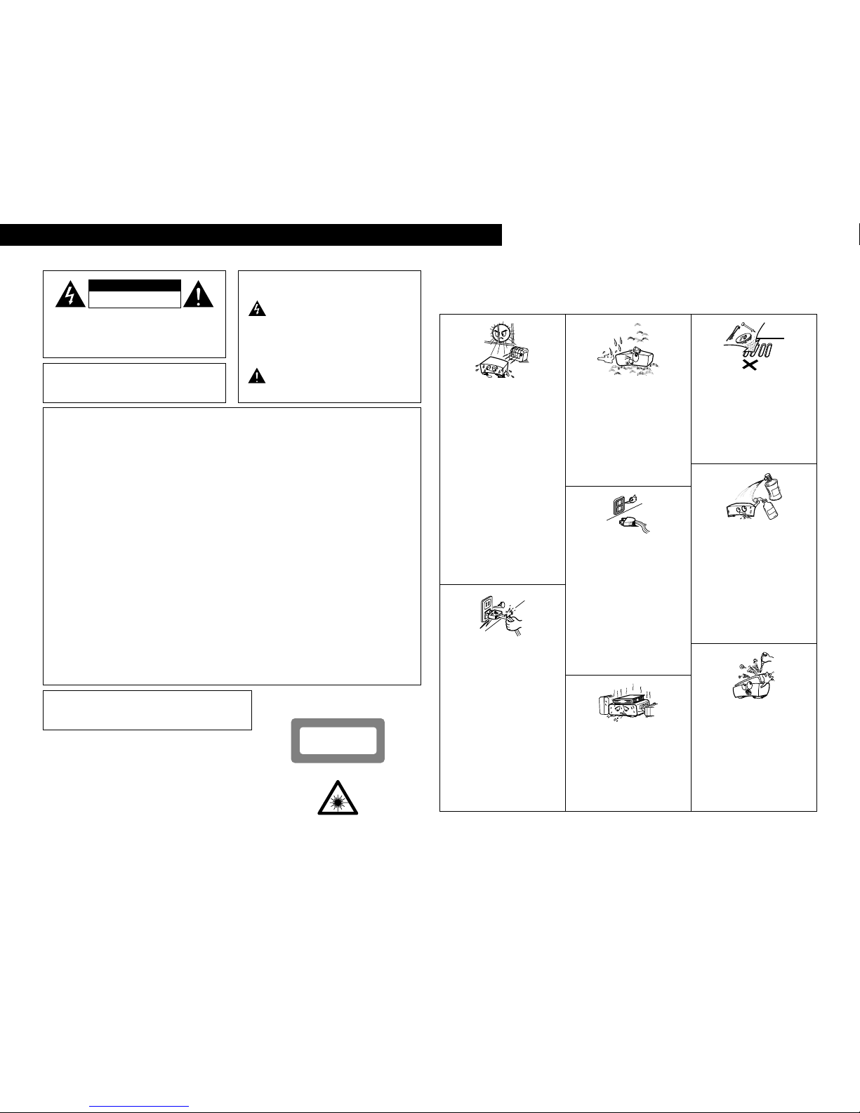
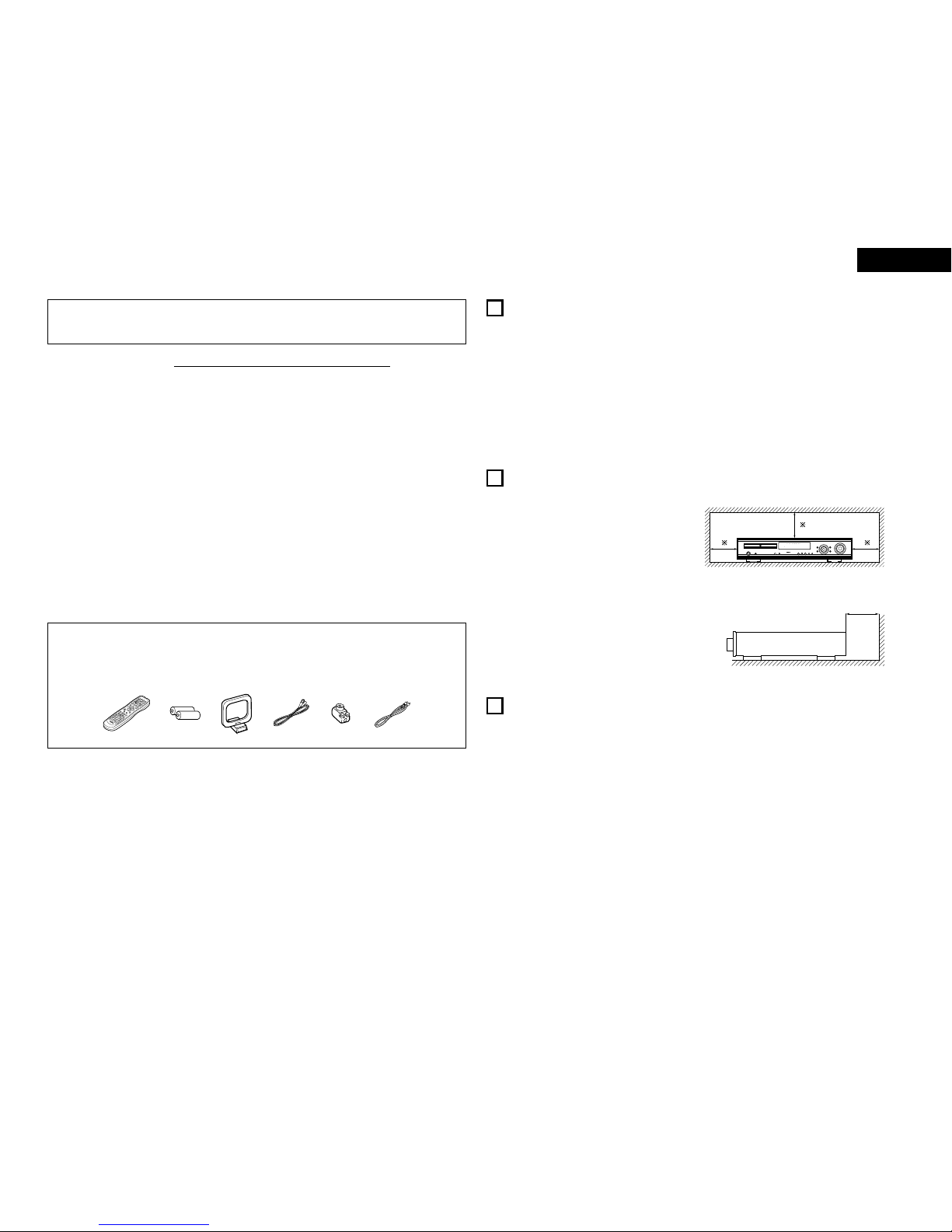
• Avoid high temperatures.
Allow for sufficient heat dispersion when
installed on a rack.
• Vermeiden Sie hohe Temperaturen.
Beachten Sie, daß eine ausreichend
Luftzirkulation gewährleistet wird, wenn das
Gerät auf ein Regal gestellt wird.
• Eviter des températures élevées
Tenir compte d’une dispersion de chaleur
suffisante lors de l’installation sur une
étagère.
• Evitate di esporre l’unità a temperature alte.
Assicuratevi che ci sia un’adeguata
dispersione del calore quando installate
l’unità in un mobile per componenti audio.
• Evite altas temperaturas
Permite la suficiente dispersión del calor
cuando está instalado en la consola.
• Vermijd hoge temperaturen.
Zorg voor een degelijk hitteafvoer indien het
apparaat op een rek wordt geplaatst.
• Undvik höga temperaturer.
Se till att det finns möjlighet till god
värmeavledning vid montering i ett rack.
• Keep the set free from moisture, water, and
dust.
• Halten Sie das Gerät von Feuchtigkeit,
Wasser und Staub fern.
• Protéger l’appareil contre l’humidité, l’eau et
lapoussière.
• Tenete l’unità lontana dall’umidità, dall’acqua
e dalla polvere.
• Mantenga el equipo libre de humedad, agua
y polvo.
• Laat geen vochtigheid, water of stof in het
apparaat binnendringen.
• Utsätt inte apparaten för fukt, vatten och
damm.
• Do not let foreign objects in the set.
• Keine fremden Gegenstände in das Gerät
kommen lassen.
• Ne pas laisser des objets étrangers dans
l’appareil.
• E’ importante che nessun oggetto è inserito
all’interno dell’unità.
• No deje objetos extraños dentro del equipo.
• Laat geen vreemde voorwerpen in dit
apparaat vallen.
• Se till att främmande föremål inte tränger in i
apparaten.
• Handle the power cord carefully.
Hold the plug when unplugging the cord.
• Gehen Sie vorsichtig mit dem Netzkabel um.
Halten Sie das Kabel am Stecker, wenn Sie
den Stecker herausziehen.
• Manipuler le cordon d’alimentation avec
précaution.
Tenir la prise lors du débranchement du
cordon.
• Manneggiate il filo di alimentazione con cura.
Agite per la spina quando scollegate il cavo
dalla presa.
• Maneje el cordón de energía con cuidado.
Sostenga el enchufe cuando desconecte el
cordón de energía.
• Hanteer het netsnoer voorzichtig.
Houd het snoer bij de stekker vast wanneer
deze moet worden aan- of losgekoppeld.
• Hantera nätkabeln varsamt.
Håll i kabeln när den kopplas från el-uttaget.
• Unplug the power cord when not using the
set for long periods of time.
• Wenn das Gerät eine längere Zeit nicht
verwendet werden soll, trennen Sie das
Netzkabel vom Netzstecker.
• Débrancher le cordon d’alimentation lorsque
l’appareil n’est pas utilisé pendant de
longues périodes.
• Disinnestate il filo di alimentazione quando
avete l’intenzione di non usare il filo di
alimentazione per un lungo periodo di tempo.
• Desconecte el cordón de energía cuando no
utilice el equipo por mucho tiempo.
• Neem altijd het netsnoer uit het stopkontakt
wanneer het apparaat gedurende een lange
periode niet wordt gebruikt.
• Koppla ur nätkabeln om apparaten inte
kommer att användas i lång tid.
• Do not let insecticides, benzene, and thinner
come in contact with the set.
• Lassen Sie das Gerät nicht mit Insektiziden,
Benzin oder Verdünnungsmitteln in
Berührung kommen.
• Ne pas mettre en contact des insecticides,
du benzène et un diluant avec l’appareil.
• Assicuratevvi che l’unità non venga in
contatto con insetticidi, benzolo o solventi.
• No permita el contacto de insecticidas,
gasolina y diluyentes con el equipo.
• Laat geen insektenverdelgende middelen,
benzine of verfverdunner met dit apparaat in
kontakt komen.
• Se till att inte insektsmedel på spraybruk,
bensen och thinner kommer i kontakt med
apparatens hölje.
• Never disassemble or modify the set in any
way.
• Versuchen Sie niemals das Gerät
auseinander zu nehmen oder auf jegliche Art
zu verändern.
• Ne jamais démonter ou modifier l’appareil
d’une manière ou d’une autre.
• Non smontate mai, nè modificate l’unità in
nessun modo.
• Nunca desarme o modifique el equipo de
ninguna manera.
• Nooit dit apparaat demonteren of op andere
wijze modifiëren.
• Ta inte isär apparaten och försök inte bygga
om den.
• Do not obstruct the ventilation holes.
• Die Belüftungsöffnungen dürfen nicht
verdeckt werden.
• Ne pas obstruer les trous d’aération.
• Non coprite i fori di ventilazione.
• No obstruya los orificios de ventilación.
• De ventilatieopeningen mogen niet worden
beblokkeerd.
• Täpp inte till ventilationsöppningarna.
* (For sets with ventilation holes)
DEUTSCH FRANCAIS ITALIANO ESPAÑOL NEDERLANDS SVENSKA
ATTENZIONE: QUESTO APPARECCHIO E’ DOTATO DI
DISPOSITIVO OTTICO CON RAGGIO LASER.
L’USO IMPROPRIO DELL’APPARECCHIO PUO’ CAUSARE
PERICOLOSE ESPOSIZIONI A RADIAZIONI!
CLASS 1 LASER PRODUCT
LUOKAN 1 LASERLAITE
KLASS 1 LASERAPPARAT
ADVARSEL: USYNLIG LASERSTRÅLING VED ÅBNING, NÅR
SIKKERHEDSAFBRYDERE ER UDE AF FUNKTION.
UNDGÅUDSAETTELSE FOR STRÅLING.
VAROITUS! LAITTEEN KÄYTTÄMINEN MUULLA KUIN TÄSSÄ
KÄYTTÖOHJEESSA MAINITULLA TAVALLA SAATTAA
ALTISTAA KÄYTTÄJÄN TURVALLISUUSLUOKAN 1
YLITTÄVÄLLE NÄKYMÄTTÖMÄLLE LASERSÄTEILYLLE.
VARNING- OM APPARATEN ANVÄNDS PÅANNAT SÄTT ÄN I DENNA
BRUKSANVISNING SPECIFICERATS, KAN ANVÄNDAREN
UTSÄTTAS FÖR OSYNLIG LASERSTRÅLNING SOM
ÖVERSKRIDER GRÄNSEN FÖR LASERKLASS 1.
,
CLASS 1
LASER PRODUCT,
,,

3
ENGLISH
2We greatly appreciate your purchase of this unit.
2To be sure you take maximum advantage of all the features this unit has to offer, read these instructions carefully
and use the set properly. Be sure to keep this manual for future reference should any questions or problems arise.
“SERIAL NO.
PLEASE RECORD UNIT SERIAL NUMBER ATTACHED TO THE REAR OF THE
CABINET FOR FUTURE REFERENCE”
TABLE OF CONTENTS
zBefore Using .....................................................................3
xCautions on Installation.....................................................3
cCautions on Handling........................................................3
vFeatures ............................................................................4
bDiscs .................................................................................4
nCautions on Handling Discs ..............................................5
mConnections..................................................................5~8
,Part Names and Functions................................................9
.Remote Control Unit.................................................10~11
⁄0 Setting up the System..............................................12~16
⁄1 Play Back ..................................................................17~18
⁄2 Operation ..................................................................19~20
⁄3 Dolby / DTS Surround...............................................20~21
⁄4 Surround Playback ....................................................22~25
⁄5 DSP Surround Simulation .........................................26~27
⁄6 Listening to the Radio ..............................................28~30
⁄7 On-Screen Display ..........................................................31
⁄8 Using the On-Screen Display....................................31~37
⁄9 Using the Timer ........................................................37~39
¤0 Changing the Default Settings (DVD) .......................40~45
¤1 Last Function Memory....................................................45
¤2 Initialization of the Microprocessor.................................45
¤3 Troubleshooting...............................................................46
¤4 Specifications..................................................................47
2ACCESSORIES
Check that the following parts are included in addition to the main unit:
erty
VOLUME
BAND
MODE
MENUFUNCTION
DISPLAYRETURNINPUTMODESURROUND
TOPMENU
SETUP
SDB/TONE
MUTE
SURR.PARA
SUBTITLEANGLE
AUDIO
SHIFT
CH.SELECT
CH
T.TONE
TU
PROG/DIRECTREPEATA-B
REPEATRANDOM
DVD
TV/VCR
CH
VOL
SLEEP
ON
OFF
REMOCONMODE
23
456
89
0
7
1
STATUS
CDR/MD/TAPETUNER/TV/VCR
VCRPOWER
TVPOWERTV
VCR
NTSC/PAL
ENTER
MUTE
ON
23
456
CLEAR
CALL
0
MEMO
POWER
CH
CH
CH
OFF
1
89
+10
7
ui
qOperating instructions…..1 wService station list............….............................1 eRemote control unit
rR6P/AA batteries..…….....2 tAM loop antenna................................…...........1 (RC-901)............…...........1
yFM indoor antenna….......1 uFM antenna adaptor…...................................... 1 iVideo cord............…........1
1BEFORE USING
Pay attention to the following before using this unit:
•Moving the set
To prevent short circuits or damaged wires in the
connection cords, always unplug the power cord and
disconnect the connection cords between all other audio
components when moving the set.
•Before turning the power switch on
Check once again that all connections are proper and that
there are not problems with the connection cords. Always
set the power switch to the standby position before
connecting and disconnecting connection cords.
•Store this instructions in a safe place.
After reading, store this instructions along with the warranty
in a safe place.
•Note that the illustrations in this instructions may differ
from the actual set for explanation purposes.
Noise or disturbance of the picture may be generated if this
unit or any other electronic equipment using microprocessors
is used near a tuner or TV.
If this happens, take the following steps:
• Install this unit as far as possible from the tuner or TV.
• Set the antenna wires from the tuner or TV away from this
unit’s power cord and input/output connection cords.
• Noise or disturbance tends to occur particularly when using
indoor antennas or 300 Ω/ohms feeder wires. We
recommend using outdoor antennas and 75 Ω/ohms
coaxial cables.
For heat dispersal, leave at least 10 cm of space between
the top, back and sides of this unit and the wall or
other components.
1
c 8 1:02:46
DVD
TONE
10 cm or more
Wall
10 cm or more
2CAUTIONS ON INSTALLATION
•Switching the input function when input jacks are not
connected
A clicking noise may be produced if the input function is
switched when nothing is connected to the input jacks. If
this happens, either turn down the MASTER VOLUME
control or connect components to the input jacks.
•Muting of PRE OUT jacks, HEADPHONE jack and
SPEAKER terminals
The PRE OUT jacks, HEADPHONE jacks and SPEAKER
terminals include a muting circuit. Because of this, the
output signals are greatly reduced for several seconds after
the power switch is turned on or input function, surround
mode or any other-set-up is changed. If the volume is turned
up during this time, the output will be very high after the
muting circuit stops functioning. Always wait until the
muting circuit turns off before adjusting the volume.
•Whenever the power switch is in the STANDBY state,
the apparatus is still connected on AC line voltage.
Please be sure to unplug the cord when you leave home
for, say, a vacation.
3CAUTIONS ON HANDLING
CAUTION:
1. Handle the power supply cord carefully
Do not damage or deform the power supply cord. If it is
damaged or deformed, it may cause electric shock or
malfunction when used. When removing from wall outlet,
be sure to remove by holding the plug attachment and not
by pulling the cord.
2. Do not open the top cover
In order to prevent electric shock, do not open the top cover.
3. Do not place anything inside
Do not place metal objects or spill liquid inside the DVD
video player.
Electric shock or malfunction may result.
NOTE:
This DVD video player uses the semiconductor laser. To allow
you to enjoy music at a stable operation, it is recommended to
use this in a room of 5°C (41°F) — 35°C (95°F).
Copyrights
2It is prohibited by law to reproduce, broadcast, rent or play
discs in public without the consent of the copyright holder.

4
ENGLISH
4FEATURES
1. Dolby Digital decoder
Dolby Digital, a digital discrete system in which the
different channels are completely independent, recreates
“three-dimensional” sound fields (sounds with a sense of
distance, movement and position) with no crosstalk
between channels for greater reality. In addition, the 5
channels (excluding the 0.1 channel for low frequency
effects) have a playback range extending to 20 kHz, the
same as the range of CDs, thus resulting in clearer, more
richly expressive sound.
2. Dolby Pro Logic II decoder
Dolby Pro Logic II is a new format for playing multichannel
audio signals that offers improvements over conventional
Dolby Pro Logic. It can be used to decode not only sources
recorded in Dolby Surround but also regular stereo sources
into five channels (front left/right, center and surround
left/right). In addition, various parameters can be set
according to the type of source and the contents, so you
can adjust the sound field with greater precision.
3. DTS (Digital Theater Systems)
DTS provides up to 5.1 channels of wide-range, high
fidelity surround sound, from sources such as laser disc,
DVD and specially-encoded music discs.
4. High performance DSP simulates 7 sound fields
Playback is possible in 7 surround modes: 5-channel
Stereo, Mono Movie, Rock Arena, Jazz Club, Video Game,
Matrix and Virtual. You can enjoy a variety of sound effects
for different movie scenes and program sources even with
stereo sources not in Dolby Surround.
5. Personal Memory Plus function
Personal Memory Plus is an advanced version of Personal
Memory. With Personal Memory Plus, the set
automatically memorizes the surround mode and input
mode for each of the separate input sources.
6. Remote control unit with pre-memory function
This unit comes with a remote control unit equipped with a
pre-memory function. The remote control command codes for
DENON remote controllable components as well as for video
decks, TVs, etc., of other major manufacturers are prestored in
the memory.
7. 5-channel power amplifier
The ADV-700 is equipped with a 35W + 35W (6 Ω/ohms, 1
kHz, T.H.D. 10%) 5-channel power amplifier, allowing 5.1-
channel surround playback when used in combination with
the super woofer.
8. Many convenient functions
(1) Multiple audio function
Selection of up to 8 audio languages.
(The number of languages offered differs from DVD to
DVD.)
(2) Multiple subtitle function
Selection of up to 32 subtitle languages.
(The number of languages offered differs from DVD to
DVD.)
(3) Multiple angle function
The angle of view can be changed.
(For DVDs on which multiple angles are recorded.)
(4) Playback disable function
This function can be used to disable playback of DVDs
you do not want children to watch.
5DISCS
• The types of discs listed on the table below can be used on the ADV-700.
The marks are indicated on the disc labels or jackets.
2The following types of discs cannot be played on the
ADV-700:
• DVDs with region numbers other than “2” or “ALL”
• DVD audio discs (NOTE 1)
• DVD-R/ –RW / +RW
• DVD-ROM/RAMs
• CVD
•SVCD
• CD-ROMs (Only MP3 file can be played)
• VSDs
• CDVs (Only the audio part can be played.)
• CD-Gs (Only the audio is output.)
• Photo CDs (NEVER play such discs on the ADV-700)
✽If you attempt to play photo CDs, the data on the disc may
be damaged.
NOTE 1: Video part which based on DVD-video specification
only can be played.
NOTE 2: According to recording quality, some CD-R/RW
cannot be played.
2Disc terminology
•Titles and chapters (DVD-videos)
DVD-videos are divided into several large sections called
“titles” and smaller sections called “chapters”.
Numbers are allotted to these sections. These numbers
are called “title numbers” and “chapter numbers”.
•Playback control (video CDs)
Video CDs including the words “playback control” on the
disc or jacket are equipped with a function for displaying
menus on the TV screen for selecting the desired position,
displaying information, etc., in dialog fashion.
In this manual, playing video CDs using such menus is
referred to “menu playback”.
Video CDs with playback control can be used on the ADV-
700.
NOTE:
• This DVD video player is designed and
manufactured to respond to the Region
Management Information that is
recorded on a DVD disc.
If the Region number described on the
DVD disc does not correspond to the
Region number of this DVD video
player, this DVD video player cannot
play this disc.
The Region number for this DVD video
player is 2.
•Tracks (video and music CDs)
Video and music CDs are divided into sections called
“tracks”.
Numbers are allotted to these sections. These numbers
are called “track numbers”.
For example:
Title 1
Chapter 1 Chapter 2 Chapter 3 Chapter 1 Chapter 2
Title 2
Track 1 Track 2 Track 3 Track 4 Track 5
2
Usable
discs Mark (logo) Recorded
signals Disc size
DVD video
DVD audio
(NOTE 1)
Digital audio +
digital video
(MPEG2)
12 cm
12 cm
12 cm
8 cm
8 cm
8 cm
Digital audio +
digital video
(MPEG1)
Digital audio
MP3
Video CD
CD
CD-R
CD-RW
(NOTE 2)
Recordable
ReWritable
For example:

5
ENGLISH
6CAUTIONS ON HANDLING DISCS
Discs
Only the discs including the marks shown on page 4 can be
played on the ADV-700.
Note, however, that discs with special shapes (heart-shaped
discs, hexagonal discs, etc.) cannot be played on the ADV-700.
Do not attempt to play such discs, as they may damage the
player.
Holding Discs
Avoid touching the surface of discs when loading and unloading
them.
Be careful not to get fingerprints
on the signal surface (the side
which shines in rainbow colors).
Cleaning Discs
2Fingerprints or dirt on the disc may lower sound and picture
quality or cause breaks in playback. Wipe off fingerprints or
dirt.
2Use a commercially available disc cleaning set or a soft cloth
to wipe off fingerprints or dirt.
Wipe gently from the middle
outwards.
Do not wipe with a circular
motion.
NOTE:
• Do not use record spray or antistatic. Also do not use
volatile chemicals such as benzene or thinner.
Record
spray
Thinner Benzene
Cautions on Handling Discs
• Do not get fingerprints, grease or dirt on discs.
• Be especially careful not to scratch discs when removing
them from their cases.
• Do not bend discs.
• Do not heat discs.
• Do not enlarge the center hole.
• Do not write on the labeled (printed) side with a ball-point
pen or a pencil.
• Water droplets may form on the surface if the disc is moved
suddenly from a cold place to a warm one. Do not use a
hairdryer, etc., to dry the disc.
Cautions on Storing Discs
• Always eject discs after playing them.
• Keep discs in their cases to protect them from dust,
scratches and warping.
• Do not put discs in the following places:
1. Places exposed to direct sunlight for long periods of time
2. Humid or dusty places
3. Places exposed to heat from heaters, etc.
Cautions on Loading Discs
• Only load one disc at a time. Loading one disc on top of
another may result in damage or scratch the discs.
• Load 8 cm discs securely in the disc guide, without using an
adapter. If the disc is not properly loaded, it may slip out of
the guide and block the disc tray.
• Be careful not to let your fingers get caught when the disc
tray is closing.
• Do not place anything but discs in the disc tray.
• Do not load cracked or warped discs or discs that have been
fixed with adhesive, etc.
• Do not use discs on which the adhesive part of cellophane
tape or glue used to attach the label is exposed, or discs
with traces of tape or labels that have been peeled off. Such
discs may get stuck inside the player, resulting in damage.
7CONNECTIONS
• Do not plug in the AC cord until all connections have been
completed.
• Be sure to connect the left and right channels properly (left
with left, right with right).
• Insert the plugs securely. Incomplete connections will
result in the generation of noise.
• Note that binding pin plug cords together with AC cords or
placing them near a power transformer will result in
generating hum or other noise.
• Noise or humming may be generated if a connected audio
equipment is used independently without turning the
power of this unit on. If this happens, turn on the power of
the this unit.
(1) Connecting the audio components
• When making connections, also refer to the operating instructions of the other components.
Connecting the DIGITAL (optical) jacks
Use these for connections to audio equipment with digital (optical) output.
NOTE:
• Use optical cables for optical connections, removing the cap before connecting.
VIDEO
MON.OUT
S VIDEO
IN IN ININ OUT
TV/DBS V.AUX VCR
R
L
AUDIO
IN OUT IN IN ININ OUT
V.AUXTV/DBS VCR
CDR/
TAPE
PRE OUT
SUB WOOFER
IN IN OUT
V.AUXTV/DBS
(OPTICAL)
DIGITAL
SPEAKER SYSTEMS
6 16 RL
RLIMPEDANCE
CENTER SURROUNDFRONT
MON.OUT
AM
FM COAX. 75
LOOP
ANT.
AV 1
OPTICAL
IN
OUTPUT
L
R
INPUT
LR
L
R
R
LL
R
L
R
B
Route the connection cords, etc., in such a way
that they do not obstruct the ventilation holes.
Subwoofer jack
Connect the internal amplifier’s subwoofer to
the subwoofer terminal. (Refer to page 8.)
•To conduct digital recording onto a digital recorder (CD recorder,
MD recorder, etc.) while playing Dolby Digital, 96 kHz PCM
sources on this DVD player.
•Set the “AUDIO SETUP” default setting as shown below. (See
page 43.)
• “DIGITAL OUT” →“PCM”
“LPCM SELECT” →“ON”
Playing DVDs with incorrect settings may result noise that could
damage your ears or the speakers.
NOTES:
• Track numbers may not be added automatically when
making digital recordings of CDs being played on the ADV-
700 onto a connected recorder.
• When making digital recordings on a CD recorder, set the
CD recorder’s recording setting to manual and add track
numbers (track marks) manually as you record.
• When making digital recordings on an MD recorder, use
the editing function after the recording is completed to
divide the tracks.
AC CORD
AC 230 V, 50 Hz
CD recorder, MD recorder or
Tape deck
Connecting a recorder
Connections for recording:
Connect the tape deck’s recording input jacks (LINE IN or REC) to
this unit’s tape recording (CDR/TAPE OUT) jacks using pin plug
cords.
Connections for playback:
Connect the tape deck’s playback output jacks (LINE OUT or PB)
to this unit’s tape playback (CDR/TAPE IN) jacks using pin plug
cords.

6
ENGLISH
(2) Connecting video components
• To connect the video signal, connect using a 75 Ω/ohms video signal cable cord. Using an improper cable can result in a drop in
video quality.
• When making connections, also refer to the operating instructions of the other components.
VIDEO
MON.OUT
S VIDEO
IN IN ININ OUT
TV/DBS V.AUX VCR
R
L
AUDIO
IN OUT IN IN ININ OUT
V.AUXTV/DBS VCR
CDR/
TAPE
PRE OUT
SUB WOOFER
IN IN OUT
V.AUXTV/DBS
(OPTICAL)
DIGITAL
SPEAKER SYSTEMS
6 16 RL
RLIMPEDANCE
CENTER SURROUNDFRONT
MON.OUT
AM
FM COAX. 75
LOOP
ANT.
VIDEO
OUT
AUDIO
OUTL
R
VIDEO
OUT
INLROUT IN L
R
AUDIO
OUT
OPTICAL
VIDEO
OUT AUDIO
OUTL
ROUT
OPTICAL
VIDEO
IN
L
R
R
L
R
L
L
R
L
RL
R
B
B
L
R
R
L
Connecting a TV/DBS tuner
TV/DBS
• Connect the TV’s or DBS tuner’s video output jack
(VIDEO OUTPUT) to the (yellow) TV/DBS IN
jack using a 75 Ω/ohms video coaxial pin plug cord.
• Connect the TV’s or DBS tuner’s audio output jacks
(AUDIO OUTPUT) to the TV/DBS IN jacks
using pin plug cords.
• For devices with optical digital outputs, connect the
digital output terminal to the ADV-700’s DIGITAL
TV/DBS IN terminal using an optical transmission
cable.
AUDIO
VIDEO
TV or DBS tuner
Monitor TV
MONITOR OUT
• Connect the TV’s video input
jack (VIDEO INPUT) to the
MONITOR OUT jack
using a 75 Ω/ohms video
coaxial pin plug cord.
VIDEO
Connecting a CS tuner
V.AUX
• Connect the CS tuner’s video output jack (VIDEO OUTPUT)
to the (yellow) V.AUX IN jack using a 75 Ω/ohms
video coaxial pin plug cord.
• Connect the CS tuner’s audio output jacks (AUDIO
OUTPUT) to the V.AUX IN jacks using pin plug
cords.
• For devices with optical digital outputs, connect the digital
output terminal to the ADV-700’s DIGITAL V.AUX. IN
terminal using an optical transmission cable.
AUDIO
VIDEO
CS tuner
Video deck
Note on connecting the digital input jacks
• Only audio signals are input to the digital
input jacks.
• Use optical cables for optical connections,
removing the cap before connecting.
Video input/output connections:
• Connect the video deck’s video output jack (VIDEO OUT) to the (yellow)
VCR IN jack, and the video deck’s video input jack (VIDEO IN) to the
(yellow) VCR OUT jack using 75 Ω/ohms video coaxial pin plug cords.
Connecting the audio output jacks
• Connect the video deck’s audio output jacks (AUDIO OUT) to the VCR IN
jacks, and the video deck’s audio input jacks (AUDIO IN) to the VCR OUT
jacks using pin plug cords.
AUDIO
AUDIO
VIDEO
VIDEO
Connecting a video decks
(3) Connecting a video component equipped with S-Video jacks
• When making connections, also refer to the operating instructions of the other components.
•A note on the S input jacks
The input selectors for the S inputs and pin jack inputs work in conjunction with each other.
•Precaution when using S-jacks
This unit’s S-jacks (input and output) and video pin jacks (input and output) have independent circuit structures, so that video
signals input from the S-jacks are only output from the S-jack outputs and video signals input from the pin jacks are only output
from the pin jack outputs.
When connecting this unit with equipment that is equipped with S-jacks, keep the above point in mind and make connections
according to the equipment’s instruction manuals.
Connecting a monitor TV
MONITOR OUT
• Connect the TV’s S video input (S-VIDEO
INPUT) to the MONITOR OUT
jack using a S jack connection cord.
S-VIDEO
VIDEO
MON.OUT
S VIDEO
IN IN ININ OUT
TV/DBS V.AUX VCR
R
L
AUDIO
IN OUT IN IN ININ OUT
V.AUXTV/DBS VCR
CDR/
TAPE
PRE OUT
SUB WOOFER
IN IN OUT
V.AUXTV/DBS
(OPTICAL)
DIGITAL
RL
RL
SURROUND
MON.OUT
AV 1
S-VIDEO
IN
S-VIDEO
OUT
S-VIDEO
OUT
S-VIDEO
IN S-VIDEO
OUT
B
B
Monitor TV
Connecting a TV/DBS tuner
• Connect the TV’s or DBS tuner’s S
video output jack (S-VIDEO
OUTPUT) to the TV/DBS
IN jack using an S jack connection
cord.
S-VIDEO
TV or DBS tuner
Connecting a CS tuner
• Connect the CS tuner’s S video output
jack (S-VIDEO OUTPUT) to the
V.AUX. IN jack using an S
jack connection cord.
S-VIDEO
CS tuner
Video deck
Connect the components’ audio inputs
and outputs as described on page 6.
Connecting the video decks
• Connect the video deck’s S output jack (S-OUT) to the
VCR IN jack and the video deck’s S input jack (S-IN)
to the VCR OUT jack using S jack connection cords.
S-VIDEO
S-VIDEO
• Connect this unit video outputs to the TV either directly.
Do not connect it via a VCR (video cassette recorder).
Some discs contain copy prohibit signals. If such discs are
played via a VCR, the copy prohibit system may cause
disturbance in the picture.
• Set the “TV TYPE” in “VIDEO SETUP” in “DVD SETUP”
to comply with your TV’s video format. When the TV is
PAL formated set to PAL.
NOTES:

7
ENGLISH
(4) Connecting the antenna terminals
R
L
SPEAKER SYSTEMS
6 16 R
L
RLIMPEDANCE
CENTER SUR
R
FRONT
AM
FM COAX. 75
LOOP
ANT.
AM LOOP
ANTENNA
(Supplied)
AM OUTDOOR
ANTENNA GROUND
FM ANTENNA
ADAPTER
(Supplied)
FM INDOOR
ANTENNA
(Supplied)
DIRECTION OF
BROADCASTING
STATION
FM ANTENNA
75 Ω/ohms
COAXIAL
CABLE
• An F-type FM antenna cable plug can be connected directly.
• If the FM antenna cable’s plug is not of the F-type, connect using the included antenna adapter.
1
4
23
AM loop antenna assembly
Connect to the AM
antenna terminals.
Bend in the reverse
direction.
Remove the vinyl tie
and take out the
connection line.
a. With the
antenna on top
any stable
surface.
Mount
b. With the
antenna
attached to a
wall.
Installation hole
Mount on wall, etc.
Connection of AM antennas
1. Push the lever. 2. Insert the conductor. 3. Return the lever.
Notes:
•Do not connect two FM antennas simultaneously.
•Even if an external AM antenna is used, do not disconnect
the AM loop antenna.
•Make sure AM loop antenna lead terminals do not touch
metal parts of the panel.
14mm
9mm
14mm
19mm
5mm
5mm
5C-2V3C-2V
5C-2V
FM antenna adopter assembly
75 Ω/ohms COAXIAL CABLE
SHUT
CLAMP
Open the cover
PULL
CLAMP
PULL
ANTENNA ADAPTER
REMOVE
CLAMP
CLAMP
SHUT
(5) Connecting to a TV with 21-pin SCART Terminal
•Use the commercially 21-pin SCART cable to connect the TV’s 21-pin SCART terminal to the ADV-700’s 21-pin SCART terminal
(AV1).
VIDEO
MON.OUT
S VIDEO
IN IN ININ OUT
TV/DBS V.AUX VCR
R
L
AUDIO
IN OUT IN IN ININ OUT
V.AUXTV/DBS VCR
CDR/
TAPE
PRE OUT
SUB WOOFER
IN IN OUT
V.AUXTV/DBS
(OPTICAL)
DIGITAL
SPEAKER SYSTEMS
6 16 RL
RLIMPEDANCE
CENTER SURROUNDFRONT
MON.OUT
AM
FM COAX. 75
LOOP
ANT.
AV 1
ADV-700
TV
21-pin SCART terminal
•The audio and video signals for the function selected on the set are output.
Audio output signals
•The tuner and DVD audio playback signals and the audio signals input to the AUDIO INPUT jacks are output.
•When a Dolby Digital DVD is played, the audio signals are converted to 2-channel signals before being output. (Audio signals
are not output during DTS playback.)
•The audio output level is fixed. If you do not wish to play the sound on the connected TV, turn the TV’s volume down to the
minimum.
Video output signals
•The DVD video playback signals and the video signals input to the VIDEO or S-VIDEO INPUT jacks are output.
•When playing a DVD, RGB video signals can also be output.
•The selection of the VIDEO, S-VIDEO and DVD RGB video signals is set at “AV1 VIDEO OUTPUT”system setup item. (By
default all are set to “VIDEO”. See page 16.)
•Some discs contain copy prohibit signals. If such discs are
played via a VCR, the copy prohibit system may cause
disturbance in the picture.
•Set the “TV TYPE“in “VIDEO SETUP“in “DVD SETUP“
to comply with your TV's video format. When the TV is
PAL formated, set to PAL. (See page 42.)
NOTES:

8
ENGLISH
(6) Sound output from this unit digital audio output connectors
2When a disc is played on the ADV-700
Settings Refer to
page Digital audio data output
Audio recording format
DVD video
DVD audio
(video part only)
Video CD
Music CD
MP3 CD
Dolby Digital
DTS
MPEG audio
48 kHz
96 kHz
CP : ON
CP : OFF
MPEG 1
Linear PCM
MP 3
Digital out : Normal
43
43
43
Dolby Digital bitstream
2 channels PCM data (48 kHz/16 bit)
DTS bitstream
2 channels PCM data (48 kHz/16 bit)
DTS bitstream
2 channels PCM data (48 kHz/16 bit)
48 kHz/16 ~24 bit PCM
48 kHz/16 bit PCM
48 kHz/16 bit PCM
48 kHz/16 bit PCM (when copy-protected)
96 kHz PCM (when not copy-protected)
44.1 kHz/16 bit PCM
44.1 kHz/16 bit PCM
32 ~ 48 kHz/16 bit PCM
Digital out : PCM conversion
Digital out : Normal
Digital out : PCM conversion
LPCM conversion mode : OFF
LPCM conversion mode : ON
LPCM conversion mode : OFF
Linear PCM
•Linear PCM audio is the signal recording format used for music CDs.
While the signals are recorded at 44.1 kHz/16 bit for music CDs, for DVDs they are recorded at 48 kHz/16 bit to 96 kHz/24 bit,
providing higher sound quality than music CDs.
(7) Speaker system connections
•Use speaker cords with twisted wire cores and a diameter
of 0.6 to 1.5 mm. Never use cords thicker than 1.5 mm or
single-wire cords, as they may damage the speaker
terminals.
•Be sure to interconnect the polarities of the terminals on the
speakers and main unit (≈to ≈, √to √).
•When making connections, be careful that none of the core
wires of the speaker cords stick out and touch neighboring
terminals, other speaker cords or the rear panel.
•Speakers with an impedance of 6 to 16 Ω/ohms can be
connected for use as center and surround speakers.
NOTE:
NEVER touch the speaker terminals when the power is
on.
Doing so could result in electric shocks.
•The protector circuit may be activated if the set is played for
long periods of time at high volumes when speakers with an
impedance lower than the specified impedance are
connected.
Connection the speaker terminals
1. Push the lever. 2. Insert the cord. 3. Return the lever.
Connections
•When making connections, also refer to the operating instructions of the other components.
VIDEO
MON.OUT
S VIDEO
IN IN ININ OUT
TV/DBS V.AUX VCR
R
L
AUDIO
IN OUT IN IN ININ OUT
V.AUXTV/DBS VCR
CDR/
TAPE
PRE OUT
SUB WOOFER
IN IN OUT
V.AUXTV/DBS
(OPTICAL)
DIGITAL
SPEAKER SYSTEMS
6 16 RL
RLIMPEDANCE
CENTER SURROUNDFRONT
MON.OUT
AM
FM COAX. 75
LOOP
ANT.
AV 1
(L) (R)
(L) (R)
FRONT SPEAKER
SYSTEMS
CENTER SPEAKER
SYSTEM
SURROUND SPEAKER
SYSTEMS
SUB WOOFER
Connector jack for subwoofer with
built-in amplifier (super woofer),
etc.
•Precautions when connecting speakers
If a speaker is placed near a TV or video monitor, the
colors on the screen may be disturbed by the speaker’s
magnetism. If this should happen, move the speaker
away to a position where it does not have this effect.
Protector circuit
•This unit is equipped with a high-speed protection circuit. The purpose of this circuit is to protect the
speakers under circumstances such as when the output of the power amplifier is inadvertently short-
circuited and a large current flows, when the temperature surrounding the unit becomes unusually high,
or when the unit is used at high output over a long period which results in an extreme temperature rise.
When the protection circuit is activated, the speaker output is cut off and the power supply indicator LED
flashes. Should this occur, please follow these steps: be sure to switch off the power of this unit, check
whether there are any faults with the wiring of the speaker cables or input cables, and wait for the unit to
cool down if it is very hot. Improve the ventilation condition around the unit and switch the power back on
If the protection circuit is activated again even though there are no problems with the wiring or the
ventilation around the unit, switch off the power and contact a DENON service center.
Note on speaker impedance
•The protector circuit may be activated if the set is played for long periods of time at high volumes when
speakers with an impedance lower than the specified impedance (for example speakers with an
impedance of lower than 4 Ω/ohms) are connected. If the protector circuit is activated, the speaker output
is cut off. Turn off the set’s power, wait for the set to cool down, improve the ventilation around the set,
then turn the power back on.

9
ENGLISH
8PART NAMES AND FUNCTIONS
Front Panel
•For details on the functions of these parts, refer to the pages given in parentheses ( ).
FUNCTION
/SELECT MASTER VOLUME
ON / STANDBY
SURROUND
MODE SDB/TONE
TIMER/SET
STATUS
OPEN/CLOSE
PHONES
DVD SURROUND
RECEIVER
ADV-700
1
c 8 1:02:46
DVD
TONE
- TUNING +
BAND
1617 1415 13
1 2 3 4 5 6 7
10 11 12
8 9
qPower button (ON/STANDBY)........................(17)
wHeadphones jack (PHONES) ..........................(20)
eRemote control signal sensor
(REMOTE SENSOR).......................................(10)
rOPEN/CLOSE button (5OPEN/CLOSE)........(17)
tPlay button (1)...............................................(17)
yPause button (3) ............................................(18)
uStop/Tuner band button (2/BAND)...........(18, 28)
iSkip/Tuner tuning –button
(8/TUNING –) ......................................(18, 28)
oSkip/Tuner tuning + button
(9/TUNING +).....................................(18, 28)
!0 Input function switching/select dial
(FUNCTION/SELECT)...................(19~20, 37~39)
!1 TIMER/SET button ...................................(37~39)
!2 MASTER VOLUME control ............................(19)
!3 SDB/TONE button ..........................................(20)
!4 SURROUND MODE button............................(19)
!5 STATUS button ...............................................(19)
!6 Display
!7 Disc tray .........................................................(17)
Remote control unit
•For details on the functions of these parts, refer to the pages given in parentheses ( ).
•Some of the buttons on the remote control unit have two functions.
The functions are switched using the remote control mode selector buttons (CDR/MD/TAPE, TUNER/TV/VCR and DVD). After
one of these buttons is pressed, the function will not switch until another remote control mode selector button is pressed.
The remote control unit’s mode switches as described below when the buttons are pressed.
VOLUME
ENTER
BAND
MODE
MENU FUNCTION
DISPLAY RETURN INPUT MODE SURROUND
TOP MENU
SETUP
SDB/TONE
MUTE
SURR.PARA
SUB TITLE ANGLE
AUDIO
SHIFT
CH.SELECT
CH
T.TONE
TU
PROG/DIRECT REPEAT A-B
REPEAT RANDOM
DVD
TV/VCR
CH
VOL
SLEEP
ON
OFF
REMOCON MODE
23
456
89
CLEAR
CALL
0
+10
7
1
STATUS
CDR/MD/TAPE TUNER/TV/VCR
VCR POWER
TV POWER TV
VCR
NTSC/PAL
MEMO
POWER
CH
CH
CH
RDS PTY CT RT
POWER ON/OFF button..........................(17)
CLEAR button ..........................................(33)
CALL button.............................................(33)
DISPLAY button .......................................(31)
RETURN button .......................................(18)
MENU button...........................................(37)
Cursor buttons .........................................(12)
System buttons .......................................(11)
*
SUBTITLE button (DVD)...........................(35)
RDS button (TUNER) .........................(11, 30)
AUDIO selector button (DVD)..................(35)
PTY button (TUNER) ..........................(11, 30)
Program/direct button
(PROG/DIRECT) .......................................(33)
A-B repeat button
(REPEAT A-B)...........................................(32)
Channel select button
(CH. SELECT)...........................................(22)
Test tone button (T.TONE) .......................(22)
SETUP button ..........................................(12)
*
System buttons .......................................(11)
SLEEP button...........................................(39)
SURROUND mode selector
button.......................................................(19)
INPUT MODE selector
button.......................................................(19)
FUNCTION selector button......................(19)
ENTER button ..........................................(12)
Main volume control buttons...................(19)
MUTE button ...........................................(20)
STATUS button ........................................(19)
NTSC/PAL button.......................................(6)
TOP MENU button (DVD) ........................(36)
RT button (TUNER) ............................(11, 30)
ANGLE button (DVD) ...............................(36)
CT button (TUNER) ..................................(11)
REPEAT button ........................................(32)
Surround parameter button
(SURR.PARA) ........................(22~24, 26~27)
SDB/TONE selector button......................(20)
Remote control mode
selector buttons
Remote control mode
CDR/MD/TAPE
TUNER/TV/VCR
DVD
Audio modes
AV modes
DVD modes
•Buttons indicated are DVD operation buttons. These can be used when the
DVD mode is selected with the remote control mode selector buttons.
•The system buttons (*) are buttons whose functions differ according to which mode
is selected with the remote control mode selector buttons.
•Other buttons are surround amplifier operation buttons that always operate in the
same way, regardless of which mode is set with the remote control mode selector
buttons.
RANDOM button .....................................(33)

10
ENGLISH
9REMOTE CONTROL UNIT
•The included remote control unit (RC-901) can be used to operate not only this unit but other remote control compatible
DENON components as well. In addition, the memory contains the control signals for other remote control units, so it can be
used to operate non-Denon remote control compatible products.
(1) Inserting the batteries
qRemove the remote control unit’s rear cover.
wSet three R6P/AA batteries in the battery compartment in
the indicated direction.
ePut the rear cover back on.
Notes on Batteries
•Use R6P/AA batteries in the remote control unit.
•The batteries should be replaced with new ones
approximately once a year, though this depends on the
frequency of usage.
•Even if less than a year has passed, replace the batteries
with new ones if the set does not operate even when the
remote control unit is operated nearby the set. (The included
battery is only for verifying operation. Replace it with a new
battery as soon as possible.)
•When inserting the batteries, be sure to do so in the proper
direction, following the “≈”and “√”marks in the battery
compartment.
•To prevent damage or leakage of battery fluid:
•Do not use a new battery together with an old one.
•Do not use two different types of batteries.
•Do not short-circuit, disassemble, heat or dispose of
batteries in flames.
•Remove the batteries from the remote control unit when
you do not plan to use it for an extended period of time.
•If the battery fluid should leak, carefully wipe the fluid off the
inside of the battery compartment and insert new batteries.
•When replacing the batteries, have the new batteries ready
and insert them as quickly as possible.
(2) Using the remote control unit
1
c 8 1:02:46
DVD
TONE
VOLUME
BAND
MODE
MENUFUNCTION
DISPLAYRETURNINPUTMODESURROUND
TOPMENU
SETUP
SDB/TONE
MUTE
SURR.PARA
SUBTITLEANGLE
AUDIO
SHIFT
CH.SELECT
CH
T.TONE
TU
PROG/DIRECTREPEATA-B
REPEATRANDOM
DVD
TV/VCR
CH
VOL
SLEEP
ON
OFF
REMOCONMODE
23
456
89
0
7
1
STATUS
CDR/MD/TAPETUNER/TV/VCR
VCRPOWER
TVPOWERTV
VCR
NTSC/PAL
ENTER
MUTE
ON
23
456
CLEAR
CALL
0
MEMO
POWER
CH
CH
CH
OFF
1
89
+10
7
30°
30°
Approx. 7m
•Point the remote control unit at the remote sensor on the
main unit as shown on the diagram.
•The remote control unit can be used from a straight distance
of approximately 7 meters from the main unit, but this
distance will be shorter if there are obstacles in the way or
if the remote control unit is not pointed directly at the
remote sensor.
•The remote control unit can be operated at a horizontal angle
of up to 30 degrees with respect to the remote sensor.
NOTES:
•It may be difficult to operate the remote control unit if the
remote sensor is exposed to direct sunlight or strong
artificial light.
•Do not press buttons on the main unit and remote control
unit simultaneously. Doing so may result in malfunction.
•Neon signs or other devices emitting pulse-type noise
nearby may result in malfunction, so keep the set as far
away from such devices as possible.
(3) Preset memory
[1] Audio Component
•The signals of your other Denon products can be stored in the
included remote control unit’s preset memory to operate
either the CDR, MD or TAPE function.
Operation is not possible for some models.
[2] TV
•Other makes of components can be operated by setting the
preset memory for your make of TV.
This remote control unit can be used to operate components
of other manufacturers without using the learning function by
registering the manufacturer of the components as shown on
the List of Preset Codes (attached sheet).
Operation is not possible for some models.
VOLUME
ENTER
BAND
MODE
MENU FUNCTION
DISPLAY RETURN INPUT MODE SURROUND
TOP MENU
SETUP
SDB/TONE
MUTE
SURR.PARA
SUB TITLE ANGLE
AUDIO
RTRDS CT
PTY
SHIFT
CH.SELECT
CH
T.TONE
TU
PROG/DIRECT REPEAT A-B
REPEAT RANDOM
DVD
TV/VCR
CH
VOL
SLEEP
ON
OFF
REMOCON MODE
23
456
89
CLEAR
CALL
0
+10
7
1
STATUS
CDR/MD/TAPE TUNER/TV/VCR
VCR POWERVCR POWER
TV POWERTV POWER TV
VCR
NTSC/PAL
MEMO
POWERPOWER
CH
CH
CH
1
1
1
1While pressing the CDR/MD/TAPE remote control mode
selector button, input the 3-digit number (“000”, “111”
and “222”) corresponding to the device you want to
preset (CDR, MD or TAPE), referring to the table below.
•Release the CDR/MD/TAPE button after inputting
three digits. This completes the presetting operation.
Table 1: Combinations of Personal System Codes
Input the 3-digit number while pressing
CDR/MD/TAPE.
CDR/MD/TAPE
0
1
1
1
2
2
2
0
0
CDR
MD
TAPE
✽This is set to CDR by factory default.
NOTE:
•Only one device (CDR, MD or TAPE) can be stored in the
preset memory.
1Press the CALL button while pressing the
TUNER/TV/VCR remote control mode selector button,
then input the three-digit number corresponding to the
code of the manufacturer of the TV whose signals you
want to store, referring to the included list of remote
control unit codes.
•Release the TUNER/TV/VCR button after inputting
three digits. This completes the presetting operation.
Example: To preset to “Hitachi 074”
Press the buttons below while pressing
TUNER/TV/VCR.
TUNER/TV/VCR
CALL
TV POWERTV POWER
0
7
4
HITACHI
“074”
✽This is set to “Hitachi 074”by factory default.
NOTE:
•Preset codes set upon shipment from the factory and
when reset.

11
ENGLISH
[3] VCR
•Other makes of components can be operated by setting the
preset memory for your make of video component.
This remote control unit can be used to operate components
of other manufacturers without using the learning function by
registering the manufacturer of the components as shown on
the List of Preset Codes (attached sheet).
Operation is not possible for some models.
(4) Operating DENON audio components
VOLUME
ENTER
BAND
MODE
MENU FUNCTION
DISPLAY RETURN INPUT MODE SURROUND
TOP MENU
SETUP
SDB/TONE
MUTE
SURR.PARA
SUB TITLE ANGLE
AUDIO
RTRDS CT
PTY
SHIFT
CH.SELECT
CH
T.TONE
TU
PROG/DIRECT REPEAT A-B
REPEAT RANDOM
DVD
TV/VCR
CH
VOL
SLEEP
ON
OFF
REMOCON MODE
23
456
89
CLEAR
CALL
0
+10
7
1
STATUS
CDR/MD/TAPE TUNER/TV/VCR
VCR POWERVCR POWER
TV POWERTV POWER TV
VCR
NTSC/PAL
MEMO
POWERPOWER
CH
CH
CH
1
1
1
VOLUME
ENTER
BAND
MODE
MENU FUNCTION
DISPLAY RETURN INPUT MODE SURROUND
TOP MENU
SETUP
SDB/TONE
MUTE
SURR.PARA
SUB TITLE ANGLE
AUDIO
RTRDS CT
PTY
SHIFT
CH.SELECT
CH
T.TONE
TU
PROG/DIRECT REPEAT A-B
REPEAT RANDOM
DVD
TV/VCR
CH
VOL
SLEEP
ON
OFF
REMOCON MODE
23
456
89
CLEAR
CALL
0
+10
7
1
STATUS
CDR/MD/TAPE TUNER/TV/VCR
VCR POWERVCR POWER
TV POWERTV POWER TV
VCR
NTSC/PAL
MEMO
POWERPOWER
CH
CH
CH
1-a,b
1
1-c,z
1Press the CLEAR button while pressing the
TUNER/TV/VCR remote control mode selector button,
then input the 3-digit number corresponding to the code
of the manufacturer of the VCR you want to store in the
memory, referring to the included table of remote
control codes.
•Release the TUNER/TV/VCR button after inputting
three digits. This completes the presetting operation.
Example: To preset to Hitachi “072”
Press the buttons below while pressing
TUNER/TV/VCR.
TUNER/TV/VCR
CALL
TV POWERTV POWER
0
7
2
HITACHI
“072”
✽This is set to Hitachi “072”by factory default.
NOTES:
•Some models and years of manufacture of components
of the manufacturers listed on the List of Preset Codes
cannot be used.
•The unit is equipped with several types of remote control
codes which depend on the manufacturer. If there is no
operation, please change the preset code (a 3-digit
number) and try again.
1DENON remote-controllable audio components can be
controlled using this unit’s remote control unit.
Note that some components, however, cannot be
operated with this remote control unit.
Before operating the remote control
unit!
Be sure to set the audio device mode
using the remote control mode selector
buttons.
a. For CDR recorder or MD recorder
CDR/MD/TAPE
VOLUME
BAND
MODE
TOP MENU
MUTE
SUB TITLE ANGLE
AUDIO
RTRDS CT
PTY
SHIFT
CH
TU
PROG/DIRECT REPEAT A-B
REPEAT RANDOM
STATUS
VCR POWER
TV POWER
NTSC/PAL
MEMO
POWER
6,7: Manual search (reverse and forward)
2:Stop
1: Play
8,9: Auto search
3: Pause
1b. For tape deck (TAPE)
VOLUME
BAND
MODE
TOP MENU
MUTE
SUB TITLE ANGLE
AUDIO
SHIFT
CH
TU
STATUS
VCR POWER
TV POWER
NTSC/PAL
MEMO
POWER
6: Rewind
7: Fast-forward
2:Stop
1: Forward Play
:: Reverse Play
Before operating the remote control
unit!
Be sure to press the proper remote control
mode selector button to set the remote
control unit to the AV mode.
c. For TUNER
TUNER/TV/VCR
VOLUME
BAND
MODE
TOP MENU
MUTE
SUB TITLE ANGLE
AUDIO
RTRDS CT
PTY
SHIFT
CH
TU
PROG/DIRECT REPEAT A-B
REPEAT RANDOM
STATUS
VCR POWER
TV POWER
NTSC/PAL
MEMO
POWER
SHIFT : Switch preset channel range
CHANNEL : Preset channel up/down
(+, –)
TUNING (+, –) : Tuning up/down
BAND : Switch between AM and FM bands
MODE : Switch between AUTO and MONO
MEMORY : Preset memory
RDS : Use this button to automatically tune to
stations using the radio data system.
RDS PTY TP
111
OFF 0
PTY : Press this button after selecting“PTY”with the
RDS button to select one of the 29 program types.
CT : Use this to correct the time of the clock on the
ADV-700. Press this button when the time service
of an RDs station is being properly received.
“TIME”is displayed for 2 seconds and the ADV-
700’s clock is corrected. “NO TIME DATA”is
displayed if the RDS station does not offer a time
service and when the broadcast is not being
received properly.
RT : Press this button when receiving RDS stations to
select the frequency, PS, PTY or RT display.
Note that this button will not function if the
reception is poor.
The display mode changes as follows each time
the button is pressed.
PS RT PTY
111
Frequency 0
(5)
Operating a video component stored in the preset memory
Before operating the remote control unit!
Be sure to press the proper remote control
mode selector button to set the remote
control unit to the AV mode.
TUNER/TV/VCR
VOLUME
ENTER
BAND
MODE
MENU FUNCTION
DISPLAY RETURN INPUT MODE SURROUND
TOP MENU
SDB/TONE
MUTE
SURR.PARA
SUB TITLE ANGLE
AUDIO
RTRDS CT
PTY
SHIFT
CH.SELECT
CH
T.TONE
TU
PROG/DIRECT REPEAT A-B
REPEAT RANDOM
TV/VCR
CH
VOL
SLEEP
ON
OFF
23
456
89
CLEAR
CALL
0
+10
7
1
STATUS
VCR POWERVCR POWER
TV POWERTV POWER TV
VCR
NTSC/PAL
MEMO
POWERPOWER
CH
CH
CH
1-a
1-b
1Operate the TV or VCR.
•For details, refer to the component’s operating
instructions.
✽Some models cannot be operated with this remote
control unit.
a. For monitor TV
MENU FUNCTION
DISPLAY RETURN INPUT MODE SURROUND
TV/VCR
CH
VOL
SLEEP
ON
OFF
23
456
89
CLEAR
CALL
0
+10
7
1
VCR POWERVCR POWER
TV POWERTV POWER TV
VCR
POWERPOWER
CH
CH
CH
TV POWER : Power on/off
CHANNEL : Switch channel
(+, –)
VOLUME : Volume up/down
(•,ª)
TV/VCR : Switch between TV and VCR
b. For video deck (VCR)
MENU FUNCTION
DISPLAY RETURN INPUT MODE SURROUND
TV/VCR
CH
VOL
SLEEP
ON
OFF
23
456
89
CLEAR
CALL
0
+10
7
1
VCR POWERVCR POWER
TV POWERTV POWER TV
VCR
POWERPOWER
CH
CH
CH
VCR POWER : Power on/off
CHANNEL : Switch channel
(+, –)
6,7: Forward and Reverse
1: Play
2:Stop

NO (power does not turn off automatically)
Setup
PAL
Default settings
QUICK SETUP
12
ENGLISH
10
SETTING UP THE SYSTEM
•Once all connections with other AV components have been completed as described in “CONNECTIONS”(see pages 5 to 8),
make the various settings described below on the monitor screen using the ADV-700’s on-screen display function.
•Use the following buttons to set up the system:
(1) System setup items
VOLUME
ENTER
BAND
MODE
MENU
DISPLAY RETURN INPUT MODE SURROUND
TOP MENU
SETUP
SDB/TONE
MUTE
SURR.PARA
SUB TITLE ANGLE
AUDIO
RTRDS CT
PTY
SHIFT
CH.SELECT
CH
T.TONE
TU
PROG/DIRECT REPEAT A-B
REPEAT RANDOM
DVD
REMOCON MODE
STATUS
CDR/MD/TAPE TUNER/TV/VCR
VCR POWER
TV POWER
NTSC/PAL
MEMO
POWER
ENTER button
Press this to switch the display.
Also use this button to complete the setting.
CURSOR buttons
and : Use these to move the cursors ( and ) to the left and right
on the screen.
and : Use these to move the cursors ( and ) to the up and down
on the screen.
SETUP button
Press this to display the system setup menu.
Setup items and default values (set upon shipment from the factory)
SPEAKER
CONFIGURATION
DELAY TIME
CHANNEL
LEVEL
AV1 VIDEO
OUTPUT
DVD AUTO
POWER OFF
DISC SETUP
OSD SETUP
VIDEO SETUP
AUDIO SETUP
RATINGS
OTHER SETUP
Input the combination of speakers in your system and
their corresponding sizes (SMALL for regular speakers,
LARGE for full-size, full-range) to automatically set the
composition of the signals output from the speakers and
the frequency response.
This parameter is for optimizing the timing with which the
audio signals are produced from the speakers and
subwoofer according to the listening position.
At the listening position, listen to the test tones output
from the different speakers and set so that the playback
level from the different speakers is equal.
The power automatically switches to standby if no
operation is performed for 30 minutes while in the stop
mode with the function set to DVD.
Set the audio language, subtitle language and disc menu
language for when playing discs.
Set the wallpaper for the setup and operation screens.
Set the screen size and video system for the TV being
used.
Set the digital audio signal format and the linear PCM
sampling frequency and bit conversion.
Make the playback restriction setting for DVDs with
restricted viewing and set the password required for
changing the setting.
Quick system settings FRONT SP.
SMALL 2.7m (9 ft)
FRONT SP.
SMALL
FRONT & SW CENTER
2.4m (8 ft)
SURROUND
2.1m (7 ft)2.7m (9 ft)
FRONT L
0 dB
DIALOG SUBTITLE DISC MENU
ENGLISH
WALL PAPER: BLUE
TV ASPECT
4 : 3 PS
DIGITAL OUT
NORMAL
RATING LEVEL
NO LIMIT
CLOSED CAPTION : OFF
TV TYPE
LPCM SELECT
OFF
PASS WORD CHANGE
0000 (Default)
ENGLISH ENGLISH
CENTER
0 dB
FRONT R
0 dB
SURROUND R
0 dB
SURROUND L
0 dB
SUB WOOFER
0 dB
CENTER SP.
SMALL
SURROUND SP.
SMALL
SUB WOOFER
YES
SW FREQ. = 120 Hz / SW MODE = NONE
CENTER SP.
SMALL 2.4m (8 ft)
SURROUND SP.
SMALL 2.1m (7 ft)
SUB WOOFER
YES 2.7m (9 ft)
ADVANCED SETUP
SYSTEM SETUP
DVD SETUP
•Speaker system layout
Basic system layout
•The following is an example of the basic layout for a system consisting of six speaker systems and a television monitor:
Subwoofer Center speaker system
Front speaker systems
Set these at the sides of the TV or
screen with their front surfaces as
flush with the front of the screen as
possible.
Surround speaker systems
VIDEO OUTPUT DVD RGB OUTPUT
VIDEO NO (VIDEO)
To select whether composite video signals or S video
signals or RGB signals will be output from the AV1 SCART
terminals.
Make the closed caption setting for DVDs. (A
commercially available decoder is required to display the
closed captions.)

13
ENGLISH
•This section describes surround-related setup operations.
For DVD-related setup operations, see page 40.
•The setup operations cannot be performed while discs are playing. Set the stop mode first.
(2) Before setting up the system
1
c 8 1:02:46
DVD
TONE
2
VOLUME
ENTER
BAND
MODE
MENU FUNCTION
DISPLAY RETURN INPUT MODE SURROUND
TOP MENU
SETUP
SDB/TONE
MUTE
SURR.PARA
SUB TITLE ANGLE
AUDIO
RTRDS CT
PTY
SHIFT
CH.SELECT
CH
T.TONE
TU
PROG/DIRECT REPEAT A-B
REPEAT RANDOM
DVD
TV/VCR
CH
VOL
SLEEP
ON
OFF
REMOCON MODE
23
456
89
CLEAR
CALL
0
+10
7
1
STATUS
CDR/MD/TAPE TUNER/TV/VCR
VCR POWERVCR POWER
TV POWERTV POWER TV
VCR
NTSC/PAL
MEMO
POWERPOWER
CH
CH
CH
5
3
2
4
1
2
Refer to “CONNECTIONS”(pages 5 to 8) and check
that all connections are correct.
Turn on the power.
Press the POWER switch (button).
ON / STANDBY
ON
POWERPOWER
Light
(green)
Main unit Remote control unit
When pressed, the power turns on and the display lights. The
sound is muted for several seconds, after which the unit
operates normally. When pressed again, the power turns off,
the standby mode is set and the display turns off.
Whenever the ON/STANDBY button is in the STANDBY state,
the apparatus is still connected on AC line voltage. Please be
sure to unplug the cord when you leave home for, say, a
vacation.
3Press the SETUP button.
SETUP
Remote control
unit
B
QUICK SETUP
<ADVANCED SETUPADVANCED SETUP>
SYSTEM SETUPSYSTEM SETUP
DVD SETUPDVD SETUP
>EXIT SETUPEXIT SETUP
DEC I S I ON : ENT ER BUTTON
SETUP MENU
SEL ECT :
4Use the and cursor buttons
on the remote control unit to select
the setting menu.
•There are three types of setup
menus.
Remote control unit
BQUICK SETUP: To switch between the 2- and 5.1-channel
modes
BSYSTEM SETUP: Detailed settings of the AV system
function
BDVD SETUP: Detailed settings of the DVD function
5Press the ENTER button to display
the setting screen of the respective
menu.
ENTER
Remote control unit
•The ADV-700 is preset with Quick System settings for a 5.1-channel surround system using five small speakers and a
subwoofer or a 2-channel virtual system using two large front speakers with or without a subwoofer.
•The system settings can be made and the ADV-700 used for playing discs simply by choosing the speaker systems you are using.
✽See “(4) System setting changes”(pages 14 to 16 when using speaker systems other than the ones described below or if you
wish to change the settings.
(3) Quick system settings (to switch between the 2- and 5.1-channel modes)
1
2
At the setup screen, select “QUICK SETUP”, then press
the ENTER button. (See page 13.)
At the quick system setting screen,
use the and cursor buttons
to select the speaker system you are
using.
•The selected speaker name is indicated in
yellow.
•The setting is displayed. Remote control
unit
B
SELECT YOUR SPEAKER SYSTEM
EXIT
5.1CH SURROUND5.1CH SURROUND
2CH VIRTUAL
2CH VIRTUAL&SW
<SETUP VALUES>
FRONT SMALLSMALL 2.7m
CENTER SMALLSMALL 2.4m
SURROUND SMALLSMALL 2.1m
SUBWOOFERSUBWOOFER YES 2.7m
DEC I S I ON : ENT ER BUTTON
QUICK SETUP MENU
SEL ECT :
3Press the ENTER button to enter the
setting.
•The setup screen reappears.
ENTER
Remote control unit
4Press the SETUP button to quit the
setup mode.
✽You can also quit the setup mode
by using the cursor button at
the setup screen to display “Quit
setup”in yellow then pressing
the ENTER button.
SETUP
Remote control
unit
✽To change the settings
At the setup screen, select “SYSTEM SETUP”from
“<ADVANCED SETUP>”.
Quick system setting parameters
5.1-channel surround system
Low frequency Delay time
playback ability (distance)
Front : Small 2.7 m (9 ft.): L2
Center : Small 2.4 m (8 ft.): L1
Surround : Small 2.1 m (7 ft.): L3
Subwoofer : Yes 2.7 m (9 ft.): L2
2-channel virtual system
Front : Large (2 channels only)
2-channel virtual + subwoofer system
Front : Large Placed at equal distances
Subwoofer : Yes
L1L2L2
L2
L3L3
Front L
Subwoofer
Center Front R
Surround L Surround R
Listening
position
Front L Front R
Subwoofer
Listening
position

14
ENGLISH
•The quick system settings and factory default settings are changed at the system setting change menu.
•The settings are stored in the memory until they are next changed, even when the power is turned off.
(4) System setting changes
[1] Setting the type of speakers
•The composition of the signals output from the different channels and the frequency response are adjusted automatically
according to the combination of speakers actually being used.
1
2
At the SETUP MENU, select “SYSTEM SETUP”and
press the ENTER button
At the SYSTEM SETUP MENU screen, use the and
cursor buttons to select the speaker system you
are using.
“SPEAKER CONFIGURATION”and press the ENTER
button.
B
SPEAKER CONFIGURATIONSPEAKER CONFIGURATION
DELAY TIMEDELAY TIME
CHANNEL LEVELCHANNEL LEVEL
AV1 VIDEOVIDEO OUTPUT
DVD AUTOAUTO POWERPOWER OFF
>SETUPSETUP MENUMENU
DEC I S I ON : ENT ER BUTTON
SYSTEM SETUP MENU
SEL ECT :
ENTER
Remote control unit Remote control unit
3Set whether or not speakers are connected and, if so,
their size parameters.
CENTER SPEAKER
FRONT SPEAKERS
SUB WOOFER
SURROUND
SPEAKERS
Remote control unit
•The item to be set is displayed in yellow, and the values of the
other items are displayed in green.
B
FRONTFRONT SP. :SP. :
CENTERCENTER SP. :
LARGELARGE SMALL NONENONE
SURROUNDSURROUND SP. :
LARGELARGE SMALL NONENONE
SUBWOOFERSUBWOOFER : YES NO
SWSW FREQ. : 120Hz
SW MODESW MODE : LFE LFELFE + MAINMAIN
FINISH: ENTER BUTTON
SPEAKER CONFIGURATION
SEL ECT :
LARGELARGE SMALL
4Enter the setting.
•The SYSTEM SETUP MENU
reappears.
ENTER
Remote control unit
NOTE:
•Select “Large”or “Small”not according to the actual
size of the speaker but according to the speaker’s
capacity for playing low frequency (approximately 100 Hz
and below) signals. If you do not know, try comparing the
sound at both settings (setting the volume to a level low
enough so as not to damage the speakers) to determine
the proper setting.
Parameters
Large…… Select this when using speakers that can fully
reproduce low sounds of below 100 Hz.
Small…… Select this when using speakers that do not
provide sufficient volume for playing low
frequencies of 100 Hz and less. When this
setting is made, frequencies below the
frequency set at the subwoofer frequency
setting are assigned to the subwoofer.
None…… Select this when no speakers are installed.
Yes/No…. Select “Yes ”when a subwoofer is installed,
“No”when a subwoofer is not installed.
✽If the subwoofer has sufficient low frequency playback
capacity, good sound can be achieved even when
“Small”is set for the front, center and surround
speakers.
✽For the majority of speaker system configurations, using
the SMALL setting for all five main speakers and
Subwoofer On with a connected subwoofer will yield the
best results.
Subwoofer frequency (SW FREQ.)
•For the subwoofer frequency at the speaker setting
screen, set the bass crossover frequency for playback
from the subwoofer.
•Select “80 Hz”, “120 Hz”, “180 Hz”or “240 Hz”(-6 dB
for each). Bass sound below these frequencies is played
from the subwoofer.
(This is set to “120 Hz”by factory default.)
Assignment of low frequencies
•In the Dolby Digital, Dolby Pro Logic II, DTS, and virtual
surround modes, the low frequency signals for channels
whose speaker settings are set to “Small”are assigned
to the subwoofer. The low frequencies of channels set
to “Large”are played from those channels.
(If set to “120 Hz”, channels set to “Small”play sounds
of 120 Hz and greater, while bass frequencies of under
120 Hz are played from the subwoofer.)
•In surround modes other than the ones listed above, low
frequencies below the frequency set at the subwoofer
frequency setting are played from the subwoofer
regardless of whether the speakers are set to “Large”or
“Small”.
•Set the subwoofer frequency according to the low
frequency playback abilities of your speakers and
subwoofer.
Subwoofer mode (SW MODE)
•The subwoofer mode setting is only valid when
“LARGE”is set for the front speakers and “YES”is set
for the subwoofer in the “SPEAKER CONFIGURATION”
settings.
•When the “LFE+MAIN”playback mode is selected, the
low frequency signal range of channels set to “LARGE”
are produced simultaneously from those channels and
the subwoofer channel.
In this playback mode, the low frequency range expand
more uniformly through the room, but depending on the
size and shape of the room, interference may result in a
decrease of the actual volume of the low frequency
range.
•Selection of the “LFE ”play mode will play the low
frequency signal range of the channel selected with
“LARGE”from that channel only. Therefore, the low
frequency signal range that are played from the
subwoofer channel are only the low frequency signal
range of LFE (only during Dolby Digital or DTS signal
playback) and the channel specified as “SMALL”in the
setup menu.
•Select the play mode that provides bass reproduction
with body.
•When the subwoofer is set to “YES”, bass sound is
output from the subwoofer regardless of the subwoofer
mode setting in surround modes other than Dolby/DTS.
\

15
ENGLISH
[2] Setting the speaker distance
•Input the distances from the listening position to the
speakers and set the surround delay time.
•The default settings below are set upon shipment from the
factory.
Preparations:
Measure the distances from the listening position to the
speakers (L1 to L3 on the diagram at the right).
FRFL
SRSL
Center
L2L1
L3
L1: Distance from center speaker to
listening position
L2: Distance from front speakers to
listening position
L3: Distance from surround speaker
to listening position
Listening
position
1
2
To perform these operations from places other than the
system setting change menu, see page 14.
At the SYSTEM SETUP MENU select “DELAY TIME”.
ENTER
Remote control unit Remote control unit
•Switch to the DELAY TIME screen.
B
2 . 7 m
2 . 4 m
2 . 1 m
FINISH: ENTER BUTTON
DELAY TIME
SEL ECT :
METERSMETERS FEETFEET
SET THE DISTANCE TO EACH SPEAKERSSET THE DISTANCE TO EACH SPEAKERS
DEFAULTDEFAULT
FRONT&SWFRONT&SW
CENTERCENTER
SURROUNDSURROUND
UNITUNIT
•Use the and cursor buttons to select the distance
unit, “METERS”or “FEET”.
Press the cursor button to proceed to the next step if
you do not wish to change this.
3When “YES”is selected for “DEFAULT”, the delay
times for the various speakers are set to the default
values.
BYES: FRONT & SW /2.7 m
CENTER /2.4 m
SURROUND /2.1 m
BNO: The current settings are used.
4Select the speaker to be set using the and
cursor buttons, then setting the distance between the
speakers and the listening position using the and
cursor buttons.
•Set the distance between the center speaker and listening
position.
The distance changes in units of 0.1 meters (1 foot) each
time the button is pressed. Select the value closest to the
measured distance.
B
2 . 4 m
2 . 1 m
FINISH: ENTER BUTTON
DELAY TIME
SEL ECT :
METERSMETERS FEET
SET THE DISTANCE TO EACH SPEAKERSSET THE DISTANCE TO EACH SPEAKERS
DEFAULTDEFAULT
FRONT&SWFRONT&SW
CENTERCENTER
SURROUNDSURROUND
UNITUNIT
2 . 7 m
✽The difference of the distances set for the different speakers
must be no greater than 3.0 m (10 ft.).
If an inapplicable distance is set, “CAUTION: INVALID
DISTANCE”is displayed. Change the speaker position and
reset.
5Enter the setting.
•The SYSTEM SETUP MENU
reappears.
ENTER
Remote control unit
[3] Setting the channel level
•Use this setting to adjust so that the playback level between
the different channels is equal.
•From the listening position, listen to the test tones produced
from the speakers to adjust the level.
•The level can also be adjusted directly from the remote
control unit. (For details, see page 22.)
1
2
To perform these operations from places other than the
system setting change menu, see page 14.
At the SYSTEM SETUP MENU select “CHANNEL
LEVEL”.
ENTER
Remote control unit Remote control unit
•Switch to the CHANNEL LEVEL screen.
B
0 d B
0 d B
0 d B
0 d B
0 d B
FINISH: ENTER BUTTON
CHANNEL LEVEL
SEL ECT :
AUTO MANUALMANUAL
TEST TONE MODETEST TONE MODE
TEST TONE STARTTEST TONE START
FRONT L
CENTER
FRONT R
SURROUND R
SURROUND L
SUBWOOFERSUBWOOFER
LEVEL CLEARLEVEL CLEAR
0 d B
3Select “TEST TONE MODE”.
•Select the mode.
Remote control unit
Select “AUTO”or “MANUAL”.
•AUTO: Adjust the level while listening to the test tones
produced automatically from the different speakers.
•MANUAL: Select the speaker from which you want to
produce the test tone to adjust the level.
4If “YES”is selected at “LEVEL CLEAR”, the level
settings for all the speakers are set to 0 dB.
B “YES”: The levels of the different speakers are all set to
0dB.
B “NO”: The speakers stay at their currently set levels.
5Adjusting the channel levels in the “test tone”mode
•Set the “TEST TONE START”mode using the
and cursor buttons, then select “YES”with the
cursor button to output test tones.
6qWhen “AUTO”is selected in the “TEST TONE
MODE”
B
YES
0 d B
0 d B
0 d B
0 d B
0 d B
FINISH: ENTER BUTTON
CHANNEL LEVEL
SEL ECT :
AUTO MANUALMANUAL
TEST TONE MODETEST TONE MODE
TEST TONE START
FRONT L
CENTER
FRONT R
SURROUND RSURROUND R
SURROUND LSURROUND L
SUBWOOFERSUBWOOFER
LEVEL CLEAR
+ 1 0 d B
•Test tones are automatically emitted from the different
speakers.
•The test tones are emitted from the different speakers in
the following order, at 4-second intervals the first time and
second time around, 2-second intervals the third time
around and on:
•
Use the CURSOR buttons to adjust all the speakers to the same
volume.
•
The volume can be adjusted between –12 dB and +12 dB in units
of 1 dB.
wWhen the “MANUAL”mode is selected
B
YES
0 d B
0 d B
0 d B
0 d B
0 d B
FINISH: ENTER BUTTON
CHANNEL LEVEL
SEL ECT :
AUTO MANUALMANUAL
TEST TONE MODETEST TONE MODE
TEST TONE START
FRONT L
CENTER
FRONT R
SURROUND RSURROUND R
SURROUND LSURROUND L
SUBWOOFERSUBWOOFER
LEVEL CLEAR
+ 1 0 d B
•Use the CURSOR and to select the speaker for
which you want to output test tones, then use the CURSOR
and to adjust so that the volume of the test tones
from the various speakers is the same.
\
\
FRONT L CENTER FRONT R
SURROUND R
SURROUND L
SUBWOOFER

16
ENGLISH
7After the above settings are completed, press the
ENTER button.
•The “SYSTEM SETUP MENU”screen reappears.
✽To cancel the setting after adjusting
Display the channel level adjustment screen, then use the
, , and cursor buttons to select “LEVEL
CLEAR”and “YES”. The level settings for all the speakers
are set to 0 dB.
NOTES:
•When you adjust the channel levels while in the SYSTEM
SETUP CHANNEL LEVEL mode, the channel level
adjustments made will affect ALL surround modes.
Consider this mode a Master Channel Level adjustment
mode.
•After you have completed the SYSTEM SETUP
CHANNEL LEVEL adjustments, you can then activate the
individual surround modes and adjust channel levels that
will be remembered for each of those modes. Then,
whenever you activate a particular surround sound mode,
your preferred channel level adjustments for just that
mode will be recalled. Check the instructions for
adjusting channel levels within each surround mode on
page 22.
[4] Setting the AV1 video output
•To select whether composite video signals or S video signals
or RGB signals will be output from the AV1 SCART terminals.
•The factory default setting is “VIDEO”and DVD RGB output
is “NO (VIDEO)”.
1
2
To perform these operations from places other than the
system setting change menu, see page 14.
At the “SYSTEM SETUP MENU”screen, select “AV1
VIDEO OUTPUT”and press the ENTER button.
ENTER
Remote control unit Remote control unit
•Switch to the “AV1 VIDEO OUTPUT”screen.
B
FINISH: ENTER BUTTON
AV1 VIDEO OUTPUT
SEL ECT :
Y E S NO ( V I DE O )
VIDEO OUTPUT
DVDDVD RGB OUTPUT
V I DEO S - V I D EO
3
4
5
Select “VIDEO OUTPUT”.
•VIDEO: Composite video signals will be output.
•S-VIDEO: S video signals will be output.
Select “DVD RGB OUTPUT”.
•NO: The video signals selected at step 3 are output.
•YES: RGB signals will be output. (DVD only)
Enter the setting.
•The SYSTEM SETUP MENU
reappears.
ENTER
Remote control unit
[5] Setting the DVD auto power off
•The ADV-700 is equipped with a function that automatically
switches the power to standby if no operation is performed
for 30 minutes while in the stop mode with the function set
to DVD. Here, set whether to turn this function on or off.
•The factory default setting is “NO”.
1
2
To perform these operations from places other than the
system setting change menu, see page 14.
•At the “SYSTEM SETUP MENU”.screen, select
“DVD AUTO POWER OFF”.and press the ENTER
button.
ENTER
Remote control unit Remote control unit
•Switch to the “DVD AUTO POWER OFF”.screen.
B
FINISH: ENTER BUTTON
DVD AUTO POWER OFF
SEL ECT :
YES NONO
(DVD FUNCTION ONLY)(DVD FUNCTION ONLY)
AUTO POWER OFFAUTO POWER OFF
3Select “YES”or “NO”.
•YES: The auto power off function is active when the function
is set to DVD.
•NO: The auto power off function does not work.
4Enter the setting.
•The SYSTEM SETUP MENU
reappears.
ENTER
Remote control unit
[6] After completing system setup
•Once the speaker settings, delay time setting and channel
level adjustments are made, there is no need to reset them
unless the AV components or speakers are changed or the
speakers are moved to different positions.
•Change the AV1 video output and DVD auto power off
settings as necessary.
1At the SYSTEM SETUP MENU,
press the SETUP button.
•The changed settings are
entered and the on-screen
display turns off.
SETUP
Remote control unit
✽This button can be pressed at any time during the system
setup process to complete the process.
NOTE:
•If the quick system settings are selected after setting up
the system using the system setting change menu, the
speaker and delay time settings are changed to the
values preset for the quick system settings.
\
\

17
ENGLISH
11
PLAYBACK
(1) Before Operating
1
c 8 1:02:46
DVD
TONE
2
MENU FUNCTION
DISPLAY RETURN INPUT MODE SURROUND
TV/VCR
CH
VOL
SLEEP
ON
OFF
23
456
89
CLEAR
CALL
0
+10
7
1
VCR POWERVCR POWER
TV POWERTV POWER TV
VCR
POWERPOWER
CH
CH
CH
2
1
2
Refer to “CONNECTIONS”(pages 5 to 8) and check
that all connections are correct.
Turn on the power.
Press the POWER
button.
ON / STANDBY
ON
POWERPOWER
Light
(green)
Main unit Remote control
unit
When pressed, the power turns on and the display lights. The
sound is muted for several seconds, after which the unit
operates normally. When pressed again, the power turns off,
the standby mode is set and the display turns off.
Whenever the ON/STANDBY button is in the STANDBY state,
the apparatus is still connected on AC line voltage. Please be
sure to unplug the cord when you leave home for, say, a
vacation.
(2) Loading Disc
2
Set discs in the disc tray with the labeled (printed) side facing
up.
1
c 8 1:02:46
DVD
TONE
8 cm disc guide
Disc tray
12 cm disc guide
NOTE:
•Do not move the this unit while a disc is playing. Doing so
may scratch the disc.
(1) Opening and Closing the Disc Tray
qTurn on the power.
wPress the OPEN/CLOSE button.
1
c 8 1:02:46
DVD
TONE
Disc tray
Power button
OPEN/CLOSE button
NOTES:
•Even when the power is in the standby mode, when the
OPEN/CLOSE button is pressed, the ADV-700’s power
turns on and the disc tray operates. (Auto power on
function)
•Even if the function is set to something other than DVD,
when the OPEN/CLOSE button is pressed, the function
switches to DVD and the disc tray operates. (Auto
function select function)
•Do not strike on the button with a pencil, etc.
(2) Loading Discs
•Pick up the disc carefully so as not to touch the signal
surface and hold it with the labeled side facing up.
•With the disc tray fully open, set the disc in the disc tray.
•Set 12 cm discs in the outer tray guide (Figure 1), 8 cm discs
in the inner tray guide (Figure 2).
•Press the OPEN/CLOSE button. The disc is automatically
loaded.
•The disc tray can also be closed automatically to load the
disc by pressing the PLAY button.
1
c 8 1:02:46
DVD
TONE
Figure 1
Outer disc tray
12 cm disc
1
c 8 1:02:46
DVD
TONE
Figure 2 Inner disc tray
8 cm disc
NOTES:
•If a foreign object is caught in the disc tray during closing,
simply press the OPEN/CLOSE button again and the tray
will open.
•Do not press the disc tray in by hand when the power is
off. Doing so will damage it.
•Do not place foreign objects in the disc tray. Doing so will
damage it.
(3) Playback
IMPORTANT SETUP INFORMATION
This set has the following presettings: “DISC SETUP”, “OSD SETUP”, “VIDEO SETUP”, “AUDIO SETUP”, “RATINGS”, and
“OTHER SETUP”.
These presettings have been preset upon shipment from the factory. If you wish to change them to suit your specific purposes,
refer to pages 40 to 45.
Before operating the remote control unit!
•Be sure to set the DVD mode using the
remote control mode selector buttons.
DVD
FUNCTION
/SELECT MASTERVOLUME
ON/ STANDBY
SURROUND
MODE SDB/TONE
TIMER/SET
STATUS
OPEN/CLOSE
PHONES
DVDSURROUND AMPLIFIER ADV-700
1
c 8 1:02:46
DVD
TONE
(3)-3
(3)-1 (3)-2,(3)-4
(3)-5 (4)-1
(5)-1
VOLUME
ENTER
BAND
MODE
MENU FUNCTION
DISPLAY RETURN INPUT MODE SURROUND
MUTE
SHIFT
CH
TV/VCR
CH
VOL
SLEEP
ON
OFF
23
456
89
CLEAR
CALL
0
+10
7
1
STATUS
VCR POWERVCR POWER
TV POWERTV POWER TV
VCR
NTSC/PAL
POWERPOWER
CH
CH
CH
(3)-7
(5)-1
(3)-6
(3)-1
(3)-5
(4)-1
(3)-6
1Turn on the power.
•Press the power button, the power indicator lights
and the power turns on.
ON
POWERPOWER
ON / STANDBY
Light
(green)
Main unit Remote control unit
2Press the OPEN/CLOSE button to open the disc tray.
OPEN/CLOSE
Main unit
3Set the disc in the disc tray.
1
c 8 1:02:46
DVD
TONE
4Press the OPEN/CLOSE button.
OPEN/CLOSE
Main unit
5Press the PLAY button.
•For many interactive DVDs and video CDs with
playback control, a menu screen appears. In this
case use the procedure in step 6 to select the
desired item.
Main unit Remote control unit
Example: For DVDs with
menu screens
Example: For video CDs with
playback control
1. Opening
Banana
Strawberry
Pineapple
TOP MENU
Orange
Peach
Apple 2. 1st movement
3. 2nd movement
4. 3rd movement
5. Ending
✽Interactive DVDs are DVDs including multiple angles,
stories, etc.

18
ENGLISH
6Use the cursor buttons ( , , and ) to select
the desired item.
•For some discs there is a second menu screen. If so,
press the 9button to display the next menu
screen. (See the disc’s jacket.)
✽The cursor buttons ( , , and ) do not
work for video CDs. Use the number buttons to
select the desired item.
Remote control unit
7Press the ENTER button.
•The desired item is selected and playback starts.
•You can return to the menu screen by pressing the
TOP MENU button while the DVD is playing, though
this depends on the disc.
•Press the RETURN button during playback of a video
CD to return to the menu screen.
ENTER
Remote control unit
Example: When “Apple”is
selected
Apple
Banana
Strawberry
Pineapple
TOP MENU
Orange
Peach
Apple
•If appears on the TV screen while buttons are
being operated, that operation is not possible on the
ADV-700 or with that disc.
•Set the disc in the disc guide.
•Only set one disc in the tray.
•The disc keeps turning while the menu screen is displayed
on the TV screen.
NOTES:
(4) Stopping Playback
1During playback, press the STOP button on the main
unit or the remote control unit, playback stops and wall
paper is displayed.
<Resume play memory function (DVD only)>
•With the ADV-700, when the STOP button is
pressed, that position is stored in the memory. At
this time, “1”flashes on the display. When the
PLAY button is pressed after pressing the STOP
button, playback resumes from the position at which
it was stopped.The resume play memory function is
cancelled if the disc tray is opened or the STOP
button is pressed a second time.
Main unit Remote control unit
✽The resume play memory function only works for
discs for which the elapsed time is shown on the
display during playback.
Auto power off function.
•The ADV-700 is equipped with a function that
automatically switches the power to standby if no
operation is performed for 30 minutes while in the
stop mode with the function set to DVD.
•This function is set to off upon shipment from the
factory. If you wish to turn it on, set the “DVD auto
power off setting”to “YES”as described on page
16.
(5) Playing Still Pictures (Pausing)
1During playback, press the PAUSE button on the main
unit or the remote control unit.
•Press the PLAY button to resume normal playback.
Main unit Remote control unit
Before operating the remote control unit!
•Be sure to set the DVD mode using the
remote control mode selector buttons.
DVD
FUNCTION
/SELECT MASTERVOLUME
ON/ STANDBY
SURROUND
MODE SDB/TONE
TIMER/SET
STATUS
OPEN/CLOSE
PHONES
DVDSURROUND AMPLIFIER ADV-700
1
c 8 1:02:46
DVD
TONE
(8)-1 (7)-1
VOLUME
ENTER
BAND
MODE
MENU FUNCTION
DISPLAY RETURN INPUT MODE SURROUND
TOP MENU
SETUP
SDB/TONE
MUTE
SURR.PARA
SUB TITLE ANGLE
AUDIO
RTRDS CT
PTY
SHIFT
CH.SELECT
CH
T.TONE
TU
PROG/DIRECT REPEAT A-B
REPEAT RANDOM
DVD
REMOCON MODE
STATUS
CDR/MD/TAPE TUNER/TV/VCR
VCR POWER
TV POWER
NTSC/PAL
MEMO
POWER
(8)-1
(7)-1
(6)-1,(9)-1
(6) Forward / Reverse Searching
1During playback, press one of the 6/ 7buttons on
the remote control unit.
6: Reverse direction
7: Forward direction
•When pressed again, the search speed increases (in
four steps).
•Press the PLAY button to resume normal playback.
Remote control unit
NOTE:
•In some cases the menu screen may reappear when
one of the 6/ 7buttons is pressed during
menu playback on a video CD.
(7) Skipping to the Beginning of Chapters or Tracks
1During playback, press one of the skip buttons on the
main unit or the remote control unit.
8/ : Reverse direction (PREVIOUS)
9/ : Forward direction (NEXT)
•A number of chapters or tracks equal to the number
of times the button is pressed is skipped.
•When the skip back button is pressed once, the
pickup returns to the beginning of the currently
playing chapter or track.
CH
Main unit Remote control unit
Playing position
Chapter/Track Chapter/Track Chapter/Track Chapter/Track
Reverse direction ,/Forward direction (direction of playback)
NOTE:
•In some cases the menu screen may reappear when
one of the 8/ 9buttons is pressed during
menu playback on a video CD.
(8) Playing Frame by Frame
(for DVDs and video CDs only)Tracks
1During playback, press the 3button on the main unit or
the remote control unit.
•The picture moves forward one frame each time the
button is pressed.
•Press the PLAY button to resume normal playback.
Main unit Remote control unit
(9)
Slow Playback (for DVDs and video CDs only)
1In the still mode, press one of the 6/ 7buttons on
the remote control unit.
6: Reverse direction
7: Forward direction
•When pressed again, the slow play speed increases.
(Four steps) (Three steps on video CDs)
•Press the PLAY button to resume normal playback.
Remote control unit
NOTE:
•Reverse slow play is not possible on video CDs.

19
ENGLISH
12
OPERATION
1
c 8 1:02:46
DVD
TONE
1,3 5
3
VOLUME
ENTER
BAND
MODE
MENU FUNCTION
DISPLAY RETURN INPUT MODE SURROUND
MUTE
SHIFT
CH
TV/VCR
CH
VOL
SLEEP
OFF 456
89
CLEAR
CALL
0
+10
7
VCR POWERVCR POWER
TV POWERTV POWER TV
POWER
CH
CH
1
3
5
2
Playing the input source
1Either turn the FUNCTION/SELECT dial on the main unit
or press the FUNCTION button on the remote control
unit to select the input source you want to play.
FUNCTION
/SELECT
FUNCTION
Main unit Remote control unit
•The function switches as shown below.
•The function only changes in the “Æ”direction when
operated from the remote control unit.
TUNER DVD
CDR/TAPE VCR
TV/DBS
V.AUX
2If “DVD”, “TV/DBS”or “V.AUX”is selected as the
input source, press the INPUT MODE button on the
remote control unit to select the input mode.
INPUT MODE
Remote control unit
AUTO PCM DTS ANALOG
•“ANALOG”cannot be selected when “DVD”is
selected as the input source.
Input mode selection function
This can be selected for the “DVD”, “TV/DBS”and
“V.AUX”input sources.
Different input modes can be selected for the
different input sources. The selected input modes
for the separate input sources are stored in the
memory.
qAUTO (auto mode)
In this mode, the types of signals being input to the
digital and analog input jacks for the selected input
source are detected and the program in the ADV-
700’s surround decoder is selected automatically
upon playback.
The presence or absence of digital signals is
detected, the signals input to the digital input are
identified and decoding and playback are performed
automatically in DTS, Dolby Digital or PCM (2
channel stereo) format. If no digital signal (TV/DBS
and V.AUX) is being input, the analog input jacks are
selected.
Use this mode to play Dolby Digital signals.
wPCM (exclusive PCM signal playback mode)
Decoding and playback are only performed when
PCM signals are being input.
Note that noise may be generated when using this
mode to play signals other than PCM signals.
eDTS (exclusive DTS signal playback mode)
Decoding and playback are only performed when
DTS signals are being input.
rANALOG (exclusive analog audio signal playback
mode)
The signals input to the analog input jacks are
decoded and played.
(This cannot be selected in the DVD mode.)
NOTE:
•The input mode is automatically set to “AUTO”when
the input is switched to DVD.
3Either press the SURROUND MODE button on the
main unit then turn the FUNCTION/SELECT dial or
press the SURROUND button on the remote control
unit to select the play mode.
SURROUND
MODE
FUNCTION
/SELECT
SURROUND
•The function switches as shown below.
•The function only changes in the “Æ”direction when
operated from the remote control unit.
STEREO
STEREO
AUTO DECODE 5CH STEREO MONO MOVIE
ROCK ARENA
DIRECT
JAZZ CLUB
VIRTUAL
VIDEO GAME
MATRIX
...
4
5
Start playback on the selected component.
•For operating instructions, refer to the component’s
manual.
Either turn the MASTER VOLUME dial on the main unit
or use the VOLUME buttons on the remote control unit
to adjust the volume.
M.VOLUME -20 The volume level is displayed on
the display.
MASTER VOLUME
VOLUME
Main unit Remote control
unit
Main unit
Main unit Remote control unit
•The volume can be adjusted within the range of –60
to 0 to 18 dB. However, when the channel level is set
as described, if the volume for any channel is set at
+1 dB or greater, the volume cannot be adjusted up
to 18 dB. (In this case the maximum volume
adjustment range is “18 dB —(Maximum value of
channel level)”.)
NOTE:
•The digital input indicator will light when “DIG”playing
CD-ROMs containing data other than audio signals, but
no sound will be heard.
Input mode when playing DTS sources
•Noise will be output if DTS-compatible CDs or LDs are
played in the “ANALOG”or “PCM”mode.
When playing DTS-compatible sources, be sure to
connect the source component to the digital input jacks
(OPTICAL/COAXIAL) and set the input mode to “DTS”.
•Noise may be generated at the beginning of playback
and while searching during DTS playback in the AUTO
mode. If so, play in the DTS mode.
STATUS
FUNCTION
/SELECT
STATUS
2Checking the currently playing program source, etc.
Either press the STATUS button on the main unit then
turn the FUNCTION / SELECT dial or press the STATUS
button on the remote control unit to check the unit’s
operating status.
Main unit Remote control
unit
Main unit
AUTO
ANA
DIG
PCM DTS
ANA
DIG
PCM
AUTO
DTS
ANA
DIG
PCM
AUTO
DTS
ANA
DIG
PCM
AUTO
DTS
Input mode display
•In the AUTO mode
•In the DIGITAL
PCM mode
•In the DIGITAL
DTS mode
•In the ANALOG
mode
One of these lights, depending
on the input signal.
Lit
PRO LOGIC II
DIG
PCM
DIGITAL
DTS
DIG
PCM
DIGITAL
DTS
DIG
PCM
DIGITAL
DTS
One of these
lights,
depending on
the input signal.
Input signal display
•DOLBY DIGITAL
•DTS
•PCM
•The “DIG”lights when digital signals are being input
properly. If the LED does not light, check whether the digital
input component setup and connections are correct and
whether the component’s power is turned on.
\
\

20
ENGLISH
After starting playback
[1] Adjusting the sound quality (SDB / TONE)
The SDB/TONE function will not work in the direct mode.
1
c 8 1:02:46
DVD
TONE
12
VOLUME
ENTER
BAND
MODE
TOP MENU
SETUP
SDB/TONE
MUTE
SURR.PARA
SUB TITLE ANGLE
AUDIO
RTRDS CT
PTY
SHIFT
CH.SELECT
CH
T.TONE
TU
PROG/DIRECT REPEAT A-B
REPEAT RANDOM
DVD
STATUS
CDR/MD/TAPE TUNER/TV/VCR
VCR POWER
TV POWER
NTSC/PAL
MEMO
POWER
1
2
2
1Press the SDB/TONE button.
•The tone switches as follows each time the
SDB/TONE button is pressed.
SDB/TONE
SDB/TONE
Main unit Remote control unit
DEFEAT SDB
(ON/OFF) BASS TREBLE
2With the name of the volume to be adjusted selected,
turn the FUNCTION/SELECT knob or cursor button (
, ) to adjust the level.
FUNCTION
/SELECT
Main unit Remote control unit
DEFEAT
•The signals do not pass through the SDB, bass and
treble adjustment circuits, providing higher quality
sound.
SDB
•
Either turn the FUNCTION / SELECT dial or use the
( , ) cursor buttons to select “ON”or “OFF”.
BASS, TREBLE
•To increase the bass or treble: Turn the control
clockwise or press the cursor button. (The bass or
treble sound can be increased to up to +10 dB in
steps of 2 dB.)
•To decrease the bass or treble: Turn the control
clockwise or press the cursor button. (The bass or
treble sound can be decreased to up to –10 dB in
steps of 2 dB.)
✽If no operation is performed within 4 seconds, the
display switches back to what was previously
displayed.
[2] Turning the sound off temporarily (MUTING)
VOLUME
BAND
MODE
TOP MENU
SETUP
SDB/TONE
MUTE
SURR.PARA
SUB TITLE ANGLE
AUDIO
RTRDS CT
PTY
SHIFT
CH.SELECT
CH
T.TONE
TU
PROG/DIRECT REPEAT A-B
REPEAT RANDOM
DVD
REMOCON MODE
STATUS
CDR/MD/TAPE TUNER/TV/VCR
VCR POWER
TV POWER
NTSC/PAL
MEMO
POWER
1
1Use this to turn off the audio output temporarily.
Press the MUTE button.
✽Cancelling MUTE mode.
Press the MUTE button again.
MUTE
Remote control unit
NOTE:
•The setting is cancelled if the set’s power is turned off.
[3] Listening over head phones
1
c 8 1:02:46
DVD
TONE
1
1Connect the headphones to the PHONES jack of the
front panel.
✽The output to the speaker automatically is turned
off and no sound is produced from the speakers.
PHONES
13
DOLBY / DTS SURROUND
Surround
This unit is equipped with a digital signal processing circuit that lets you play program sources in the surround mode to achieve the
same sense of presence as in a movie theater.
Dolby Surround
(1) Dolby Digital (Dolby Surround AC-3)
Dolby Digital is the multi-channel digital signal format developed by Dolby Laboratories.
Dolby Digital consists of up to “5.1”channels - front left, front right, center, surround left, surround right, and an additional
channel exclusively reserved for additional deep bass sound effects (the Low Frequency Effects –LFE –channel, also called
the “.1”channel, containing bass frequencies of up to 120 Hz).
Unlike the analog Dolby Pro Logic format, Dolby Digital’s main channels can all contain full range sound information, from the
lowest bass, up to the highest frequencies –22 kHz. The signals within each channel are distinct from the others, allowing
pinpoint sound imaging, and Dolby Digital offers tremendous dynamic range from the most powerful sound effects to the
quietest, softest sounds, free from noise and distortion.
2Dolby Digital and Dolby Pro Logic
Comparison of home surround
systems
No. recorded channels (elements)
No. playback channels
Playback channels (max.)
Audio processing
High frequency playback limit of
surround channel
Dolby Digital
5.1 ch
5.1 ch
L, R, C, SL, SR, SW
Digital discrete processing Dolby Digital (AC-3)
encoding/decoding
20 kHz
Dolby Pro Logic
2 ch
4 ch
L, R, C, S (SW - recommended)
Analog matrix processing Dolby
Surround
7 kHz
2Dolby Digital compatible media and playback methods
Marks indicating Dolby Digital compatibility: and .
The following are general examples. Also refer to the player’s operating instructions.
Media
LD (VDP)
DVD
Others
(satellite broadcasts, CATV, etc.)
Dolby Digital output jacks
Coaxial Dolby Digital RF output jack
1
Optical or coaxial digital output
(same as for PCM)
2
Optical or coaxial digital output
(same as for PCM)
Playback method (reference page)
Set the input mode to “AUTO”.
(Page 19)
Set the input mode to “AUTO”.
(Page 19)
Set the input mode to “AUTO”.
(Page 19)
1 Use a commercially available adapter to connect Dolby Digital RF (AC-3RF) output signals to the digital input terminals.
(Refer to the adapter’s operating instructions.)
Please refer to the instruction manual of the adapter when making connection.
2 To play in Dolby Digital Surround on the ADV-700, set “DVD setting change”–“Audio setting”–“Digital output”to
“Normal”in the setup. (The factory default is “Normal”.)
Other manuals for ADV-700
6
Table of contents
Languages:
Other Denon Home Cinema Speakers manuals