Der Mann mit der Maschine DROID MASTER User manual

Universal CV Processor
User manual
for firmware version green-8
November 21, 2021

Contents
1 Quick start 4
2 Installation 5
3 Creating DROID patches 6
3.1 General procedure . . . . . . . . . . . . . . . . . . . . . . . . . . . 6
3.2 Finding a problem in your DROID patch . . . . . . . . . . . . . . . . 7
3.2.1 Examples for error codes . . . . . . . . . . . . . . . . . . . . 8
3.2.2 Table of error codes . . . . . . . . . . . . . . . . . . . . . . . 9
3.3 Basic structure of the patch file . . . . . . . . . . . . . . . . . . . . . 10
3.4 Inputs, output and other registers . . . . . . . . . . . . . . . . . . . 10
3.5 Numbers and voltages . . . . . . . . . . . . . . . . . . . . . . . . . 12
3.6 Attenuating and offsetting inputs . . . . . . . . . . . . . . . . . . . 13
3.7 Internal patch cables . . . . . . . . . . . . . . . . . . . . . . . . . . 14
3.8 Using outputs as inputs . . . . . . . . . . . . . . . . . . . . . . . . . 15
3.9 Using inputs as outputs . . . . . . . . . . . . . . . . . . . . . . . . . 15
3.10 The order of the circuits . . . . . . . . . . . . . . . . . . . . . . . . 16
3.11 Parameter arrays . . . . . . . . . . . . . . . . . . . . . . . . . . . . 16
3.12 Comments & spaces . . . . . . . . . . . . . . . . . . . . . . . . . . 16
3.13 How the module’s state is saved . . . . . . . . . . . . . . . . . . . . 17
3.14 More than one patch on the memory card . . . . . . . . . . . . . . . 17
3.15 Displaying the value of a register . . . . . . . . . . . . . . . . . . . . 18
4 Controllers and Expanders 19
4.1 The P2B8 controllers . . . . . . . . . . . . . . . . . . . . . . . . . . 20
4.2 The P10 controllers . . . . . . . . . . . . . . . . . . . . . . . . . . . 22
4.3 The G8 expander . . . . . . . . . . . . . . . . . . . . . . . . . . . . 24
5 Firmware upgrade 25
5.1 What version do you have? . . . . . . . . . . . . . . . . . . . . . . . 25
5.2 Normal update procedure . . . . . . . . . . . . . . . . . . . . . . . 25
5.3 Upgrade from green to blue . . . . . . . . . . . . . . . . . . . . . . 27
6 Calibration & Factory Reset 28
6.1 The maintainance mode . . . . . . . . . . . . . . . . . . . . . . . . 28
6.2 Factory reset . . . . . . . . . . . . . . . . . . . . . . . . . . . . . . 29
6.3 Calibration . . . . . . . . . . . . . . . . . . . . . . . . . . . . . . . 29
7 Hardware 31
8 Reference of all circuits 32
8.1 adc – AD Converter with 12 bits . . . . . . . . . . . . . . . . . . . . 33
8.2 algoquencer – Algorithmic sequencer . . . . . . . . . . . . . . . . . 35
8.3 arpeggio – Arpeggiator – pattern based melody generator . . . . . . 46
8.4 bernoulli – Random gate distributor . . . . . . . . . . . . . . . . . 52
8.5 burst – Generate burst of pulses . . . . . . . . . . . . . . . . . . . . 53
8.6 buttongroup – Connected buttons . . . . . . . . . . . . . . . . . . . 55
8.7 calibrator – VCO Calibrator . . . . . . . . . . . . . . . . . . . . . 58
8.8 chord – Chord generator . . . . . . . . . . . . . . . . . . . . . . . . 60
8.9 clocktool – Clock divider / multiplier / shifter . . . . . . . . . . . . . 64
8.10 compare – Compare two values . . . . . . . . . . . . . . . . . . . . . 66
8.11 contour – Contour generator . . . . . . . . . . . . . . . . . . . . . . 68
8.12 copy – Copy a signal . . . . . . . . . . . . . . . . . . . . . . . . . . 73
8.13 crossfader – Morph between 8 inputs . . . . . . . . . . . . . . . . . 74
8.14 cvlooper – Clocked CV looper . . . . . . . . . . . . . . . . . . . . . 75
8.15 dac – DA Converter with 12 bits . . . . . . . . . . . . . . . . . . . . 77
8.16 droid – General DROID controls . . . . . . . . . . . . . . . . . . . . 79
8.17 euklid – Euclidean rhythm generator . . . . . . . . . . . . . . . . . 80
8.18 explin – Exponential to linear converter . . . . . . . . . . . . . . . . 82
8.19 fold – CV folder – keep CV in certain bounds . . . . . . . . . . . . . . 84
8.20 fourstatebutton – Button switching through 4 states . . . . . . . . 86
8.21 lfo – Low frequency oscillator (LFO) . . . . . . . . . . . . . . . . . . 87
8.22 logic – Logic operations utility . . . . . . . . . . . . . . . . . . . . 92
8.23 math – Math utiliy circuit . . . . . . . . . . . . . . . . . . . . . . . . 95
8.24 matrixmixer – Matrix mixer for CVs . . . . . . . . . . . . . . . . . . 97
8.25 midifileplayer – MIDI file player . . . . . . . . . . . . . . . . . . . 99
8.26 midiin – MIDI to CV converter (EXPERIMENTAL) . . . . . . . . . . . 103
8.27 midiout – MIDI to CV converter (EXPERIMENTAL) . . . . . . . . . . . 104
8.28 minifonion – Musical quantizer . . . . . . . . . . . . . . . . . . . . 105
8.29 mixer – CV mixer . . . . . . . . . . . . . . . . . . . . . . . . . . . . 108
8.30 motoquencer – Sequencer using motor faders (EXPERIMENTAL) . . . . 109
8.31 motorfader – Create virtual fader in M4 controller . . . . . . . . . . . 111
8.32 notchedpot – Helper circuit for pots . . . . . . . . . . . . . . . . . . 112
8.33 notebuttons – Note Selection Buttons . . . . . . . . . . . . . . . . . 113
8.34 nudge – Modify – “nudge” – a value using two buttons . . . . . . . . . 114
8.35 octave – Multi-VCO octave animator . . . . . . . . . . . . . . . . . 116
8.36 quantizer – Non-musical quantizer . . . . . . . . . . . . . . . . . . 118
2

8.37 queue – Clocked CV shift register . . . . . . . . . . . . . . . . . . . . 119
8.38 random – Random number generator . . . . . . . . . . . . . . . . . . 120
8.39 sample – Sample & Hold Circuit . . . . . . . . . . . . . . . . . . . . 121
8.40 sequencer – Eight step sequencer . . . . . . . . . . . . . . . . . . . 122
8.41 slew – Slew limiter . . . . . . . . . . . . . . . . . . . . . . . . . . . 125
8.42 superjust – Perfect intonation of up to eight voices . . . . . . . . . . 127
8.43 switch – Adressable/clockable switch . . . . . . . . . . . . . . . . . 129
8.44 switchedpot – Overlay pot with multiple functions . . . . . . . . . . 131
8.45 togglebutton – Create on/off buttons . . . . . . . . . . . . . . . . . 133
8.46 transient – Transient generator . . . . . . . . . . . . . . . . . . . . 136
8.47 triggerdelay – Trigger Delay with multi tap and optional clocking . . 138
DROID manual for green-8 3 Table of contents at page 2

1 Quick start
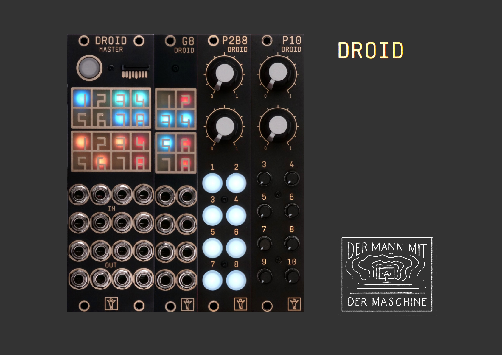
Welcome to the . The is a very flexi-
ble generic CV processor. It can do almost any CV task
you can imagine, such as sequencing, melody generation,
slew limiting, quantizing, switching, mixing, working on
clocks and triggers, creating envelopes and LFOs or other
fancy voltages, or any combination of these at the same
time! While doing this, is very precise both in volt-
age and in timing.
You tell your what to do by means of a sim-
ple text file called “DROID patch”. That file is be named
droid.ini and is located on a micro SD card. No spe-
cial software is required for writing that file. A simple
text editor running on Windows, Linux, Mac or any other
device will suffice. If you have an X7 expander attached
to your master, you can access the memory card directly
from your PC or Mac via a USB-C cable.
The building blocks of a DROID patch are called circuits.
Every type of circuit performs some basic task. Just like a
Eurorack module each ciruit has inputs and outputs. You
can wire these either directly to some of the inputs and
outputs of the module or even connect them in-
ternally in order to create more complex networks of cir-
cuits.
A first patch example – step by step
Let’s do a first simple DROID patch!
1. Install your DROID master into your Eurorack sys-
tem and power it on.
2. Remove the shipped micro SD card from your
DROID master und put it into the micro SD card
reader that also as been shipped with your DROID.
Insert that reader into a free USB port of you Laptop
or PC. (Alternatively, if you have an X7 attached,
connect the X7 with a free USB port of your com-
puter and put the switch on the X7 to the left).
3. Locate the file droid.ini on that card with your
file browser (Explorer, Finder, whatever) and open
it with a text editor (like Notepad, TextEdit, VIM,
Notepad++, etc.).
4. Delete the current contents of that file and type the
following:
[contour]
gate = I1
decay = 0.2
sustain = 0.5
release = 0.3
output = O1
5. Save the file back to the SD card, eject the card
properly and then remove it from the reader.
6. Insert the card back into the DROID master – with
the visible pins facing downwards.
7. Press the button left of the card slot
If you have an X7, simply put the switch back to its cen-
ter position after ”ejecting” the SD card with windows /
Mac. It will then automatically load the new patch with-
out need to press the button.
Your DROID now will read in its new patch. If everything
goes well, it restarts with its rainbow color animation. If
not please check your DROID patch and repeat the proce-
dure. Refer to page 7for how to find the root cause of a
problem.
This first patch creates an ADSR type envelope that is
triggered at input jack 1 (I1) and outputs its CV on output
jack 1 (O1). For the parameters A, D, S and R fixed values
are being set for the while.
Now within the every parameter can be controlled
via CV. So instead of setting the release to a fixed value of
0.3 you can use the second input (I2) for CV controlling
that. This is easy:
[contour]
gate = I1
decay = 0.2
sustain = 0.5
release = I2
output = O1
If you have a controller such as the P2B8, the P4B2 or the
P10, you can use pots for controlling parameters. First
of all – for each P2B8 you need one line with the contents
[p2b8]. Likewise for a P4B2 you need the line [p4b2] and
for a P10 the line [p10]. (Note: If you mix P2B8s, P4B2s,
P10s and other controllers, the order of these controllers
in your chain must match the order of the declaration in
your DROID patch.) Now you can access the first pot of
your first controller with P1.1, e.g. in order to control the
sustain of the envelope via that pot:
[p2b8]
[contour]
gate = I1
decay = 0.2
sustain = P1.1
release = I2
output = O1
We have not dug into details yet – but you get the idea!
The rest of this manual will show you the wonderful world
of the . First you learn all general ideas and fea-
tures. In chapter 8there is a complete rereference of all
circuit types that you offers.
DROID manual for green-8 4 Table of contents at page 2

2 Installation
Controller connector
The connector for the controllers has 6 pins (two
rows of three pins) and is used for connecting a
chain of P2B8,P4B2,B32,P10,M4 and other
controllers. Please refer to page 20 for details.
Programming port
The 6 pin programming port is not mounted in a
box. Caution: Do not connect anything to this
port! It is solely for the initial programming in our
labs. Later firmware upgrades are done via the
Micro SD card. Expansion port for G8
The connector for the G8 expander has 8 pins (two
rows of four pins). Here you can add one op-
tional G8 expander for an additional 8 gate in-
puts/outputs. Please refer to page 24 for details.
Power connector
The power connector has 10 pins (two rows of five
pins). Use the shipped 10 pin ribbon cable in order
to connect it with the bus board of your Eurorack
case. Important: Put the red stripe down! Do not mix up the connectors! This will destroy
your electronics. Do not force in cables in the
wrong orientiation or with the wrong number of
pins! Do not attach anything to the program-
ming port.
DROID manual for green-8 5 Table of contents at page 2

3 Creating DROID patches
3.1 General procedure
Writing a patch is what makes the come to
live. Without a patch your is pretty useless. This
is the general procedure of creating and loading a patch
into your :
1. Create a text file called droid.ini.
2. Copy this file to a micro SD card.
3. Insert the card into your master.
4. Press the button on the master.
If the finds an error in your patch then LEDs will
blink and tell you more about that error. Fix your error
and try again. That’s all.
If you have an X7 expander attached to your master, the
whole procedure is a lot easier. The X7 gives you direct
USB access to the SD card. The card is attached to your
computer by putting the little switch on the X7 to the left.
This is like inserting the card into your computer. Now
you can edit or copy your droid.ini. Afterwards simply
put the switch back to its center position. That will re-
move the card from your computer (eject it first with your
file browser). Also the patch will be immediately loaded
by your master, no need to press the button.
Procedure in details
Here is the procedure again with some more details:
1. Use your PC, Mac or Linux box for creating a text
file with the name droid.ini. A text file is not a
MS Word file. In Windows you can create or edit a
text file with Notepad or with some more conve-
nient text editor. Note: some might want to edit
droid.ini directly on the SD card. This is possbile,
of course. It’s always handy, however, to have a
copy of that file on your computer, just in case.
2. When you are finished, copy this file to the micro
SD card your has been shipped with or to
any other micro SD card that is compatible with
. You need a micro SD card reader for this.
Do not use any subdirectories on the card. Put the
file into the main directory. The card needs to be
formatted with the standard FAT filesystem. If you
buy a new card it is most likely formatted that way
anyway. Hint: If you like you can create and edit
your file directly on the card, of course. This saves
the extra step of copying it.
3. Insert the micro SD card into the small card slot
of your master. Put it in with the metal
contacts downwards. Be gentle, as always :-)
4. Press the button left of the SD card slot. Of
course your has to be powered up while
you do this. The now reads the file
droid.ini, copies it into its internal flash mem-
ory and restarts, in order to load and activate the
new patch. If everything is OK, you will see a nice
startup animation with rainbow colors and your
patch is up and running. After that you can remove
the card if you like. Your does not need it
anymore.
Note: If you are using an X7 expander, the memory
card remains in the master module all the time. You
also don’t need to press the button on the master,
just use the switch on the X7.
DROID manual for green-8 6 Table of contents at page 2

3.2 Finding a problem in your DROID patch
It is not entirely unlikely that you got something wrong
in your patch, some syntax error, some invalid line, stuff
like that. Humans make errors, but this is no big deal,
since helps you finding the reason and location
of any problem in your patch by two means:
1. It creates a file called DROIDERR.TXT on your SD
card.
2. It flashes some LEDs in a certain way.
So if you experiance any strange LED blinkings after load-
ing your patch, put the card back into your computer (or
put the switch on your X7 to the left again) and look into
the file DROIDERR.TXT, which should be there now. This
file just contains one line, maybe like this one:
ERROR IN LINE 17: Invalid output 'O9'. Allowed
is O1 ... O8
This explains you the exact location and reason of your
problem so that you can easily fix it.
LED blink codes
As an alternative to the error file, the master also
shows the location and reason of the error in form of LED
blink codes. There are two types of errors that you can
make:
1. General errors concern the patch as a whole. The
SD card is missing. You have missspelled the file
name. Things like that. In such a case all LEDs will
flash in the same color. The color indicates the
reason of the error. On the next page you find a
table of all global error codes.
2. Local errors concern just one specific line in your
patch. In that case just some of the LEDs
will flash. The color, again, shows you the error
reason, according to the table local error codes. In
addition, the LEDs show you the exact line number
where your error occurs. This is done in the follow-
ing way:
• The input LEDS 1 … 8 indicate the tens of the
line number. If the error happens to be in line
90, then LED 1 + 8 will flash. If it is in line 1 to
9, then no input LED flashes at all.
• The output LEDS 1 … 8 indicate the “ones”
and are added to that number. Again, if a 9
is needed, then 8 + 1 will flash.
• If your patch has more than 99 lines, then the
error could be in line 100+. In that case one
of the input LEDs will flash white. That LED
indicates the hundreds of the line number.
• If your patch has more than 999 lines, you are
crazy.
DROID manual for green-8 7 Table of contents at page 2

3.2.2 Table of error codes
All LEDs flashing at once (global error)
yellow Patch not found: This can happen in the following situations:
1. No file with the name droid.ini is present on the memory card.
2. You started without having loaded a patch ever.
3. You did a factory reset without loading a patch afterwards.
orange Empty patch: Your droid.ini file has a size of 0 bytes. Or it could not
be read correctly. Check the file. Maybe reinsert the micro SD card and
try again.
red Too many controllers: You have declared more than the allowed num-
ber of 16 controllers.
blue Patch is too big: The size of your droid.ini file is too big. The maxi-
mum of the size without spaces and comments is 64,000 bytes – which
is pretty much.
cyan Out of memory: The circuits in your patch use too much memory. So
you have too many large circuits or too many circuits in total. The mem-
ory consumption of each circuit only depends on its type. The smallest
circuit is bernoulli and has a size of about 200 bytes. The largest cir-
cuits are midifileplayer with 7000 bytes and cvlooper with 18,000
bytes. Most circuits need between 400 and 800 bytes. And the total
available memory is about 110,000 bytes.
magenta Invalid firmware file: The firmware upgrade files because the contents
of droid.fw is invalid. The file is incomplete or corrupted.
white No SD card found: No card could be found. Maybe you inserted it in the
wrong way? Or your card is not supported. Or you pressed the button
too early. Sometimes it helps to simple press the button again.
Note: If you get your start animation with just white LEDs instead of colored ones, your
DAC calibration needs to be redone. See page 29 for details.
Just some of the LEDs flashing (local error in one line in droid.ini)
yellow Unknown register: You used a non-existing register name (registers are
the things like O1,I7 and so on). Please check the list of allowed regis-
ters in this manual on page 11.
orange Unknown parameter name: that circuit does not support that param-
eter. Please check the reference of all circuits in chapter 8.
red Unknown circuit: This type of circuit does not exist. Please check the
exact spelling. Maybe you have an old firmware that does not support
that circuit yet? On page 25 you learn how to do a firmware upgrade.
blue Line too long: One line in your patch exceeded the maximum allowed
line length of 127 characters.
cyan Too many constants: Your patch uses too many different fixed
values like 1.0 or 0.5. You are limited to 40 different fixed values.
green Internal patch cable missused: One of your internal patch cables (see
page 14) is not properly used:
1. No input: One patch cable is only used as output.
2. No output: One patch cable is only used as input.
3. Double output: One patch cable is used twice as an output.
magenta 1. Invalid header of circuit: was expecting an opening square
bracket [, but found something else.
2. Invalid parameter line: was expecting something like clock
= I7, but found something completely different. Parameters always
start with a letter. Then comes an equal.
3. Invalid parameter value: Your parameter has an invalid value.
Please checkout this manual about allowed values for parameters and
their exact syntax.
DROID manual for green-8 9 Table of contents at page 2

3.3 Basic structure of the patch file
The file droid.ini is a simple text file. This has lots of
advantages:
• You can edit it with nearly every operating system.
• No special software is needed. This will probably
still work in 30 years, when you just have bought
a vintage on ebay for a couple thousand
bucks.
• You can easily post and share your patches
or snippets from there on our Discord community
or on other internet boards.
• You can copy & paste parts from other one’s
patches.
• You can add comments into your patch.
Here – again – is an example of a patch:
[lfo]
hz = 0.5
triangle = _CABLE_1
[contour]
gate = I1
decay = _CABLE_1
sustain = P1.1
release = I2
output = O1
As you can see the droid.ini is a list of circuit declara-
tions. In the upper example we see two circuits: [lfo]
and [contour]. Each one comes with a list of inputs and
outputs which are assigned to jacks, fixed values or inter-
nal patch cables.
In the example all jack declarations are indented. But this
is just for better readability.
3.4 Inputs, output and other registers
Your has lots of inputs and outputs. Also its LEDs
behave like outputs and buttons and pots behave like in-
puts. All these are called registers, because they behave
like things that can store values. Each register special
character followed by a number or number combination.
Most important of course are the eight CV input and and
ouput jacks. With the normalizations N1,N2, … N8 you can
specify a signal that should be used for I1,I2, … I8 when
no patch cable is inserted. But we will come to that later.
When you have attached the G8 expander than you have
eight more jacks called G1 through G8. Each of these can
either be used as an input or an output. They are simple
gate inputs/outputs that just know on and off, or 0 and 1.
When used as an output they output either 0 V or roughly
5 V.
The stuff on your P2B8, P4B2, B32, P10 and other con-
trollers can also be accessed via registers. Here there is
always a dot in the name, separating two numbers, like
P1.2 or B4.8. The first number is always the number of
your controller. The second number is the number of the
element on the controller. So B4.8 is the 8th button on
the 4th controller. P10 controllers just have Pregisters,
no Bor Lregisters. Likewise the B32 has just buttons and
thus no Pregisters.
Please note that each button has two registers: one for
the button itself. It will be 1.0 if the button is pressed
and 0.0 if it is released. The second register if for the LED
in the button. These are output registers where you can
write values into. A value of 0.0 will make the LED off,
while 1.0 creates full brightness. But the LEDs also sup-
port any number inbetween and will have a brightness ac-
cording the that number. Negative numbers are treated
like positive numbers here, so -0.5 will produce the same
brightness as 0.5.
As long as you do not actively use the L-registers the
LED in a button will automatically be lit while you hold
it. Please look at the togglebutton circuit in page 133
for how to convert a push button into one that toggles it
state on each press.
The registers R1 through R24 let you override the func-
tion of the LEDs for the inputs, outputs and gates. This
is sometime very useful when you have a couple of un-
used inputs (and thus unused LEDs). Sending some inter-
nal values to one of these LEDs gives you some feedback
about what your is doing.
DROID manual for green-8 10 Table of contents at page 2

Here is the complete table of all register types:
Register Type Description
I1 I2 I3 I4 I5 I6 I7 I8 input The eight inputs of the master
N1 N2 N3 N4 N5 N6 N7 N8 output The normalization of these inputs (i.e. the voltage they get when nothing is patched)
O1 O2 O3 O4 O5 O6 O7 O8 output The eight outputs of the master
G1 G2 G3 G4 G5 G6 G7 G8 input/output The eight gate jacks of the G8 expander. Each can be used either as an input or as an output.
R1 R2 R3 R4 R5 R6 R7 R8 output The colored LED squares in the first two rows (those for the inputs)
R9 R10 R11 R12 R13 R14 R15 R16 output The colored LED squares in row three and four (those for the outputs)
R17 R18 R19 R20 R21 R22 R23 R24 output The colored LED squares on the G8 expander (those for the gates)
P1.1 P1.2 P2.1 P2.2 P3.1 P3.2 … input The pots on your P2B8, P4B2 or P10 controllers. P3.2 is the 2nd pot on your 3rd controller.
B1.1 B1.2 B2.1 … B2.1 B2.2 B2.3 … input The push buttons on your P2B8, P4B2 or B32 controllers. B3.6 is the 6th push button on your 3rd controller.
L1.1 L1.2 L2.1 … L2.1 L2.2 L2.3 … output The LEDs in that these push buttons
DROID manual for green-8 11 Table of contents at page 2

3.5 Numbers and voltages
How voltages are converted
is a CV processor that inputs and outputs con-
trol voltages. But internally it works with just numbers,
because this is much more conveniant. Here is how the
operates:
1. When reading voltages from the input jacks, these
are converted from the range -10 V to +10 V into
the number range from -1 to +1.
2. All circuits operate one these numbers.
3. When sending numbers to the output jacks, the
numbers are converted back from -1 to +1 to the
voltage range -10 V to +10 V.
This means that if the reads a voltage of 2.5 V at
one of its inputs, in the patch this will appear as
0.25. Or if you send a value of 0.5 to one of the outputs,
that will result in exactly 5.0 V there. This is in fact very
conveniant as you will see.
Voltages out of range
The ’s hardware cannot work with voltages be-
yond ±10 V. Anyway, Eurorack is limited to ±12 V and
barely any module reaches even 10 V at its output (in fact
many digital modules are limited to the range 0 V...5 V,
which I think is a bad idea).
That simply means that any voltage out of that range ap-
pearing at an input is simply truncated. Send -10.8 V at an
input and will see it as -10 V. Or send the number
1.1 to an output (which would be 11 V) and it will output
10 V nevertheless.
But: internally – in your patch – numbers can get
arbitrarily low or high. So in intermediate steps it’s abso-
lutely no problem to work with larger numbers. It’s com-
pletely normal. Some circuits even require such numbers.
E.g. in the minifonion (see page 105) you specify the
root note B by saying root = 11. On the side of the jacks
that would mean 110 V, but that’s not relevant here.
For those of you wanting to dig more into the de-
tails of number processing: works inter-
nally with 32 bit floating point values. The ex-
ponent is 8 bits. The largest number is slightly
above 300000000000000000000000000000000000000
(a 3 with 38 zeroes).
The smallest number greater than zero is approximately
0.000000000000000000000000000000000000011
(that’s 37 zeroes after the decimal point). The negative
range is simliar.
One word to the G8 expander: it’s outputs can only out-
put two possible voltages: 0 V and 5 V. The rule is: any
number >=0.1 sent to one of its registers G1 ... G8 will
set its output to 5 V, any other number to 0 V.
Specifying numbers in your patch
Note: you always need to write the numbers in ”plain”
format, for example 0.01 or 12345.67 or -5.0. Scientific
notations like 3.4^-10 are not allowed. It’s also not al-
lowed to write just .5 instead of 0.5.
There are two suffixes that you can attach to a number:
%and V. Appending a percent sign basically divides the
number by 100, so ...
pulsewidth = 45%
... is just the same as
pulsewidth = 0.45
Appending a Vdivides the number by 10, which is exactly
what you need in order to convert a number to a voltage
to be output at a jack. So:
pitch = 2V
... is just the same as
pitch = 0.2
Sometimes this is easier to read. Please be just aware that
the Vis applied just to the number itself. You could write
1/12V, but that is not 1
12 V, but is 1
12V, which is – when
you convert the voltage back to a number – 1
1.2, which is
0.8333. Whereas 1
12 V would be 0.008333 – a hundred
times smaller!
Some inputs or ouputs behave like gates that only know
0 or 1, low or high, on or off. For your ease you can use
the words off – which is just a short hand for 0.0, and on
– which stands for 1.0, if you like. Here is an example:
[contour]
loop = on
output = O1
This is exactly the same as:
[contour]
loop = 1.0
output = O1
DROID manual for green-8 12 Table of contents at page 2

3.6 Attenuating and offsetting inputs
Attenuation / Amplification / Multiplication
Each input of a circuit (not the outputs!) has a builtin op-
tion for attenuation and offsetting. Attenuation is done
by multiplying the input with a value. Well, if you “atten-
uate” with a number greater than 1, the name attenua-
tion would not really be correct, since the signal in fact
gets amplified and not attenuated.
Let’s assume you want to control the level parameter
of an LFO with the first pot of your first controller (see
page 87 for details on the LFO circuit). That pot can be
addressed with P1.1:
[lfo]
level = P1.1
output = O1
The pot has a range from 0 to 1, which corresponds to 0 V
…10 V. That’s maybe too much for you application. So
let’s limit the range to 5 V, which is the same as 0.5. This
is done by multiplying the pot with 0.5:
level = P1.1 * 0.5
Now level will range from 0 V to 5 V.
The attenuation does not need to be a fixed number. Let’s
CV control the level of the LFO with the external input I1.
Now we multiply that with the pot P1.1, which makes the
latter an attenuator for the CV. How cool is that?
level = I1 * P1.1
Fixed numbers can also be negative. The following line
basically inverts the LFO’s output since its output voltage
is negated:
level = P1.1 * -1
If you like, you can use a short hand for that:
level = -P1.1
But that is really just an abbreviation for -1 * P1.1.
From that follows, that -P1.1 * I1 is not possible, since
this would be -1 * P1.1 * I1, which would be two mul-
tiplications!
Division
There is another shorthand: It is allowed to use division,
if the thing you divide by is a fixed number. So Instead of
pitch = I1 * 0.0833333 you can write:
pitch = I1 / 12
Again, this is a short hand for I1 * 0.0833333 and this
its treated as a multiplication. For that reason you can-
not write I1 / P1.1 or anything similar, since here the
would really have to do a dynamich division with
the current value of P1.1. Use the math circuit for such
things (see page 95).
Offsets / Summing
An offset is applied by adding a number. This must be
written after the (optional) attenuation. Let’s have the
level of the LFO set by P1.1 but be at least 2 V:
[lfo]
level = P1.1 + 0.2
Now the level would range from 2 V to 12 V. Since 10 V
is the maximum, we could multiply the pot with 0.8 first,
which results in a range from 2 V to 10 V:
level = P1.1 * 0.8 + 0.2
Again you are not restricted to fixed numbers. You can
also use any register you like. In this example
we use P1.1 as a coarse tune and P1.2 as a fine tune (20
times finer) for the rate of an LFO:
[lfo]
square = O1
rate = 0.05 * P1.2 + P1.1
Using +can even be used for mixing together two input
signals. The circuit copy just copies an input to an output,
but since the offset can be used with any register you can
build a simple CV mixer:
input = I1 + I2
Note: If you want to sum more than two signals, use the
mixer circuit (see page 108 for details).
Substraction
Mathematics says, that substraction is nothing else than
the addition of a negative number. So you can substract
0.5 from P1.1 by writing:
input = P1.1 + -0.5
Since this looks clumsy, you are allowed to write as a
short hand:
input = P1.1 - 0.5
DROID manual for green-8 13 Table of contents at page 2

Note: you can also use the negation on a register:
input = I1 - I2
But note: here this is an abbreviation for -1 * I2 + I1!
So you already have “used up” your multiplication, even
if you don’t see it. The general rule is: If can trans-
form your line into the form A *B+C, everything is good.
Summary and Further notes
• Generally spoken the format is A *B+C. So you are
limited to one attenuation (multiplication) and one
offset (addition / substraction)
• Each of A, B and C can be a fixed number, any of
the registers or an internal patch cable (for those
see page 14).
• Attenuation must be written first, offset last.
• There are some abbreviations for substraction and
division. They work if the thing can be transformed
into A *B+C.
• No other operations are allowed (no brackets, ad-
ditional operations, divisions, etc.)
• If you need more complex math operations, have a
look at the math circuit (see page 95).
Are you curious why does not allow more com-
plex operations here? Why is it so restrictive? The rea-
son is a matter of CPU performance! When your patch is
parsed, everything is converted to A *B+C. If you don’t
use the multiplication, B is set to 1. No offset? Then C
is 0. So when it comes to the real time computation of
these values, it’s just the simple A *B+C. No conditions
to be tested, no if/then/elses or similar stuff. It’s really
super fast. And that’s important because you want your
to have a low latency smooth envelopes.
3.7 Internal patch cables
One of the fun part of the is the fact, that you can
internally connect several circuits without using any real
inputs or ouputs. Here instead of an output you simply
put a name of your choice that begins with an underscore.
That same name can be used at another circuit as an in-
put. Here is an example of an internal LFO triggering an
envelope:
[lfo]
square = _TRIGGER
[contour]
trigger = _TRIGGER
output = O1
This patch cable is always a multiple, so it can be used by
more than one circuit:
[lfo]
square = _TRIGGER
[contour]
trigger = _TRIGGER
attack = 0.0
release = 0.2
output = O1
[contour]
trigger = _TRIGGER
attack = 0.5
release = 0.8
output = O2
Note: There are two rules, which are checked by the
. And it will show an error message in green if one
these are found to be broken (see page 7for an explana-
tion of the error codes).
1. Each internal patch cable must be used as an input
and as an output (otherwise it would be useless).
2. No internal patch cable may be used twice as an
output. This would make no sense and is in effect
a short cut.
DROID manual for green-8 14 Table of contents at page 2

3.8 Using outputs as inputs
There is another way of connecting circuits: You can use
an output register as an input to another circuit. The
following example creates an LFO that outputs a square
wave to LED R1, in order to have that flashing in the speed
of the LFO. R1 is the LED designated for input 1, but we
simply missuse that as a signal LED for our LFO. Then an
euclidean rhythm is triggered with that same signal, sim-
ply by using R1 as an input here:
[lfo]
hz = 2
square = R1
[euklid]
clock = R1
length = 12
beats = 5
output = O1
3.9 Using inputs as outputs
Using input registers as outputs is not allowed. And it
would not make any sense. If you try so, you will get a
yellow blinking error message for the according line.
Look at the following example. Here – due to a copy &
paste error – the LED states are sent to the button regis-
ters. That won’t work. And for that reason won’t
allow it:
[buttongroup]
button1 = B1.1
button2 = B1.2
button3 = B1.3
led1 = B1.1 # Argr. should be L1.1!
led2 = B1.2 # Argr. should be L1.2!
led3 = B1.3 # Argr. should be L1.3!
DROID manual for green-8 15 Table of contents at page 2

3.10 The order of the circuits
You might ask yourself what role the order of the circuits
plays in your patch file. Well – in most cases it doesn’t
matter at all, in some cases, however, it might cause very
subtle timing differences in the range of a couple of hun-
dred µs. In order to understand this, we need to have a
closer look at how the DROID works:
The basic working hourse of your DROID is simple loop
that is repeating over and over again – at a speed of ap-
proximately 180 µs per cycle, which means that is run-
ning at approximately 5.5 kHz! In each cycle of the loop
the following things happen:
• The current values of all inputs, gates, buttons and
pots are read in and stored in the I,G,Band Preg-
isters.
• Each circuits creates a new value for each of its out-
puts. That might include writing new values into O,
G,Lor Rregisters.
• The contents of the Oand Gregisters are converted
into voltages for the according output jacks. The
contents of the Land Rregisters are translated into
brightness and color of the according LEDs.
Now let’s look at two circuits that are internally wired:
[bernoulli]
input = G1
distribution = P1.1
output1 = _TRIGGER
[contour]
trigger = _TRIGGER
output = O1
Here an external trigger at G1 (on the G8 expander) is ran-
domly being used to trigger an envelope, which is then
sent to O1. Here – because of the order of the circuits –
the envelope will start in the same loop cycle in which the
trigger is seen at G1.
Now let’s change the order:
[contour]
trigger = _TRIGGER
output = O1
[bernoulli]
input = G1
distribution = P1.1
output1 = _TRIGGER
Now it is different. In the loop cycle in which the trigger is
detected at G1 the envelope has already been processed.
It gets its trigger through the internal wire _TRIGGER not
before the next cycle. This introduces a short delay of
up to 160 µs. This is not very long, but it can be easily
avoided.
Note: When your patch contains quit a lot circuits, the
loop time gets longer of course. It is very likely that is is
below 500 µs even then, however.
3.11 Parameter arrays
Some of the circuits have arrays of similar jacks, like
output1,output2,output3 and so on. Here you always
can omit the digit 1if you just want to address the first
jack in the list. So output is just the same as output1
here.
3.12 Comments & spaces
You can use comments in your patch by making
use of #. Then all further text until the end of the line is
being ignored: #Here comes the envelope for the foobar
voice
[contour]
trigger = _TRIGGER # wired to sequencer
attack = 0.5 # another comment
release = 0.8
output = O2 # wired to foobar trigger
DROID manual for green-8 16 Table of contents at page 2

3.13 How the module’s state is saved
If you ask people what’s the number one annoyance that
a module can have, most will answer this: When a mod-
ule is loosing its state when you power off and on your
modular. That’s also the number one reason for people
letting run their system the whole night through.
Therefore the – of course – will save it’s state al-
ways automatically. But what do I mean with “state” in
the first place? It’s very simple: If you have defined a
togglebutton, remembers wether it is currently
on or off. If it is on now, so will it be after a power cycle
of your system or a restart of the module (the same holds
for off, of course).
Other ciruits have states as well, for example the
algoquencer (state of the step buttons, the accents, the
pattern length), the matrixmixer (state of all matrix but-
tons), the calibrator (state of the calibration adaption),
the switchedpot (the current value of all up to eight vir-
tual pots) and so on.
Only the result of manual interaction is saved, not for ex-
ample the contents of the cvlooper or the current phase
of an lfo.
Please note: All these states are saved to the micro SD
card into a file with the name DROIDSTA.BIN. That file
is created with a fixed size of 128 KB when your
starts. All manual changes to your circuits are saved there
after a short delay of about 1.5 seconds. Also when you
press the button for loading a new patch, the states are
saved immediately, even if the last change was less than
1.5 seconds ago.
From this follow a couple of things:
• When no memory card is in the , no states
will be saved. But you can always put one there
even if the module is already running for some
time. It will be detected automatically and all
states will be saved after a second or two.
• When you move the SD card from one
to another, the current circuit states will also be
moved.
• If you want to erase all your settings, you can do
this by starting the without and SD card
and inserting it later. The settings file will just be
loaded right at the beginning. If it’s not present, all
circuits start with their default settings.
The format of the file is binary and looks chaotic. You
cannot open or edit it with any software. But the format
is very efficient, so the ongoing saving of states doesn’t
have any impact on the precise timing or performance of
the .
Note: If you forget to have the SD card inserted when you
power up your , it will run with default states. In-
serting the SD card afterwards will not load the saved set-
tings but the other way round! It will save the new states
on the card. That way you loose your original settings.
So if you have forgotten to start with the card, power
off the module, then insert the card, then power it on
again. That way you won’t loose your settings.
3.14 More than one patch on the memory card
Sometimes you might want to have more than one
patch on your card and switch back and forth be-
tween these without going back to your computer. This
can easily be done if you have at least one controller with
buttons, such as P2B8, P4B2 or B32.
It goes like this: Put your additional patches on the card
with special filenames. It is droidXY .ini, where Xis
the number of the controller and Ythe number of the
button. Then droid14.ini will be loaded if you first press
and hold the button 4on your first controller while then
pressing the load button on the master.
That way if you have one P2B8 you can choose between
nine different patches. If you have a second P2B8 con-
troller, this is extended to 17 patches, because now hold-
ing button 1 on controller 2will load droid21.ini and
so on. A B32 gives you a total of 32 alternative patches
to load and so on. And yes: if you have 10 or more
controllers and some B32 amongst them, droid124.ini
would be loaded by button 24 on controller 1, but also by
button 4 on controller 12.
Important: It is crucial that every of your patch files con-
tains the appropriate [p2b8] or other controller declara-
tions! Otherwise you won’t be able to switch over to the
other patches since button presses will not longer be reg-
istered by the master. It will instead fall back to
the normal droid.ini in that case.
DROID manual for green-8 17 Table of contents at page 2

3.15 Displaying the value of a register
Sometimes you want to know the exact value of one of
the registers, for example if you are OK with setting a pa-
rameter to a fixed value but first want to try out which
value fits bets your needs. Maybe you need a simple en-
velope with a fixed non-zero attack value. You could try
out different values by changing your patch over and over
again. But that’s quite annoying.
Here the experimental X1 register helps. It’s an output
register. When you send a value there, all the LEDs of the
front panel will show that value in a way similar to the
line-error-encoding of the patch parser. Here is an exam-
ple:
[p2b8]
[contour]
attack = P1.1
release = P1.2
trigger = B1.1
output = O1
[copy]
input = P1.1
output = X1
Now turn the knob P1.1 for setting some nice attack
value. As soon as you remove that from its zero-position,
all LEDs will move around in red and white and show the
current value of P1.1 with three digits. Input LEDs are lit
white and red. White digits account for 0.1 and red digits
for 0.01. The red digits at the outputs account for 0.001.
Here are some examples:
The value 0.148:
The digit 9 will be displayed as 8 + 1. So here is 0.951:
A zero digit means of course that no LED is lit in the ac-
cording section. Here is 0.950:
But what if digits in the input section collied? E.g. 0.550
would need the LED of input 5 to be red and white at the
same time. Well, then it will blink between white and red:
Once you have found a nice value, simply replace P1.1
with that fixed value and your pot if free for something
else!
Note: When you send 0 to the X1 register, it will be inac-
tive and the LEDs behave like normal and show the actual
values of your inputs and outputs.
DROID manual for green-8 18 Table of contents at page 2

4 Controllers and Expanders
The master can be extended with a ever growing range of controllers and other expanders. These are what makes the ecosystem so flexible. You can attach up to 16
controllers to your .
The P2B8 controller
has two poten-
tiometers (pots) and
eight push buttons
– thus the name
P2B8. You can freely
use these pots and
buttons them for
any purpose in your
patch. Using
controllers is very
easy and adds lots of
playability.
The P10 is available
since summer 2021
and works very sim-
ilar to the P2B8, just
it has not buttons but
10 pots. Two are
large and eight are
small, but all of them
have the same func-
tionality. You can
control any parame-
ter you like with each
of the pots.
The G8 expander
extends your
by eight gate inputs
or outputs, which
is perfect for clock,
trigger and gate
signals. Every jack
can be used as a gate
input or output. You
can attach one G8 to
your .
The P4B2 controller
will be available early
2022 and is very similar
to the P2B8. The only
difference is that it has
four big pots and just
two buttons. They are
useful if you need more
controls of continous
values but the small
pots of the P10 are too
small for you.
The B32 controller
will also be available
early 2022. It does
not have any pots
but 32 buttons.
The M4 Motor Fader
Unit brings four
motorized faders to
your . These
can be used either
for easy switching
between presets or
for overloading one
fader with lots of
different functions
at the same time.
They will be available
in spring 2022.
The X7 expander is sched-
uled for early 2022 and is a
combination of three things:
An USB connector for di-
rect access to the masters’s
SD card so you won’t need
to swap the card anymore.
Also you can do MIDI in/out
via USB. Then it has MIDI
in and out via TRS (3,5mm
stereo jacks). And finally it
has four gate outputs.
DROID manual for green-8 19 Table of contents at page 2

4.1 The P2B8 controllers
Using controllers is very easy and adds lots of playabil-
ity to your DROID patch. The P2B8 controller is the most
common and flexible of the controllers and it also
was the first to be avaiable. This chapter shows you how
to install and use it. But all of this also holds for the P4B2,
P10 and B32 controllers – just that the P10 has no buttons
and the B32 has no pots. The M4 is special and will be de-
scribed in an own chapter once it is avaiable.
Installation
1. Wire the controller output of the master to the first
controller by use of the 6 poled ribbon cable. Make
sure that you attach it to the input header of the
P2B8 controller. Put the red stripe down on both
modules.
2. If you use more than one controller, connect the
output header of each controller to the input
header of the next one.
3. On the last controller, set the jumper to Last.
4. On all other controllers, remove the jumper or set
it to Park.
Note (1): do not mix up input and output. The right
connector must be connected to the master, the left
one to the next controller.
Note (2): do not use the 6 pin programming header
(that without the box) on your master or P2B8!
The controllers are powered by the master. If you switch
on your system, all controllers will flash the LEDs for a
short time. That shows you that you have wired them
correctly.
If you haven’t placed the jumpers correctly, the con-
trollers will power up and flash their LEDs anyway, but
you will not be able to get the buttons and pots to work.
If the LEDs on the first controller behave as they should
but not the buttons and pots then you have probably set
the jumpers incorrectly. Please check.
Another test is pressing a button: If you have corrected
listed your controllers in your DROID patch, the LED in
that button should be lit as long as you hold the button.
From that you can see that the communication with the
master is working perfectly.
DROID manual for green-8 20 Table of contents at page 2
This manual suits for next models
4
Table of contents
Popular Controllers manuals by other brands

Mitsubishi Electric
Mitsubishi Electric MELSEC FX Series Structured programming manual

Motorline
Motorline MC61 User& installer's manual

Krom Schroder
Krom Schroder IC 40 operating instructions

STEEL-PLAY
STEEL-PLAY PRO Instructions for use

M-Elec
M-Elec ML-2820 manual

EQ3
EQ3 HmIPW-DRS4 Installation instructions and operation manual