Derale Perfomance 16016 Service manual

PRE INSTALLATION
PULLER APPLICATION
1. Electric Fan is setup from the factory for Puller applications and requires no
modification.
2. Check product label on Electric Fan shroud. The arrow on the label shows
airflow direction through the fan.
PUSHER APPLICATION
1. Remove the nut/clip that holds fan blade to motor shaft.
2. Remove fan blade from motor shaft. This is an interference fit andNote:
requires some effort. Be careful not to damage fan blade.
3. Flip blade over and align groove in fan blade with roll pin on motor shaft.
4. Reinstall nut/clip on motor shaft.
INSTALLATION INSTRUCTIONS
ELECTRIC FAN
PART # 16016
16016-InstructionSheet Rev.04202018
Dyno-Cool by Derale, Los Angeles, CA 323.266.3850 www.derale.com
Please read these instructions completely before beginning installation
PARTS LIST
QTY. DESCRIPTION
1 Electric Fan
6 Mounting Rods
6 Mounting Clips
2 Mounting Feet
7 1x1 Foam Pads
1 Thermostat Switch
1 Relay Wire Harness
1 7 Ft. 14 Ga. Wire
1 3/8” NPT Thread-in Probe
QTY. DESCRIPTION
1 Push-in Probe
1 Retaining Probe Clip
1 Blue 5/16” Ring Terminal
2 Blue #10 Ring Terminal
1 Blue Butt Connectors
2 Blue Female Connectors
2 Blue Wire Tap Connectors
4 4” Wire Ties
2 #10 Sheet Metal Screw
TOOLS NEEDED
12V Test Light
Wire Stripper
Crimping Tool
3/4” Wrench
Teflon Tape
Standard Screw Driver or
a 5/16” Nut Driver
Drill
5/32” Drill Bit
Dyke Pliers
IMPORTANT
This fan assembly is designed
for both PULLER and
PUSHER APPLICATIONS.
(See Diagram #1)
Puller Fan Pusher Fan
Air Flow
Engine Radiator
Diagram #1
(Continues on Page 2)
ELECTRIC FAN MOUNTING
Note: This Electric Fan Assembly requires 6 mounting positions. Four Mounting Rods will be installed in the locations molded in
the shroud, the additional two Mounting Rods will be used with the 2 supplied Mounting Feet. (See Diagram #2)
1. Identify the 2 Mounting Feet supplied and install onto the Electric Fan Assembly by sliding them into the slots on the Electric
Fan Assembly. See Diagram #2 for recommended locations.
2. Position the electric fan against the radiator in the desired location.
3. Take the Plastic Rods provided and install
through the mounting holes on the shroud
pushing them slowly into and through the
radiator core.
Caution: Do not use excessive force when
pushing Plastic Rods through radiator core.
Excessive force could cause damage to the
radiator fins and/or core. Plastic Rods should
not be inserted thru both the radiator and the
condenser cores.
4. Take the 1 x 1 Foam pads provided and install
them onto the Plastic Rods now protruding
through the radiator core.
5. Take the Plastic Clips provided, making sure
they are in the correct direction (Derale writing
out) install onto the Plastic Rods and cinch them
until the 1 x 1 Foam Pads are compressed.
6. Cut off the excess Plastic Rod.
Diagram #2
Mounting Clips
1 x 1
Foam
Pads
Mounting
Feet
Mounting
Rods
Dyno-Cool by Derale, Los Angeles, CA 323.266.3850 www.derale.com
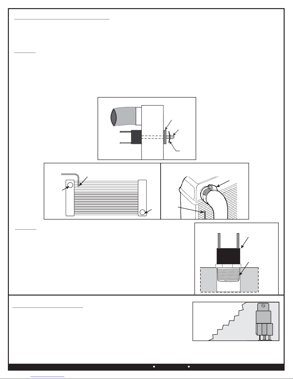
THERMOSTAT PROBE INSTALLATION
This kit includes two thermostat probe options.
Choose the option that best fits your application.
Option 1 - Push-in Radiator Probe (See Diagram #4)
Option 2 - Thread-in Radiator Probe (See Diagram #6)
Option 1
Placement: For best results we recommend installing the Push-in Probe as close as possible to the water inlet of the radiator.
(See Diagram #5)
Installation:
1. Take the Push-in Probe and thread it clockwise onto the Thermostat Switch.
2. Carefully insert the probe/thermostat assembly into the fins of the radiator until Thermostat Switch is flush with radiator.
3. Install the 1 x 1 foam pad onto the Push-in Probe.
4. Install Retaining Clip onto the Push-in Probe until tight. (See Diagram #4)
Push-in
Radiator
Probe
Down-flow Radiator
Option 2
Placement: Locate a 3/8” NPT port either on the radiator, waterneck, intake
manifold or cylinder heads.
Installation:
1. Using Teflon tape or suitable sealant install the probe into the 3/8” NPT
Thread-in Probe on the vehicle.
2. Using a 3/4” wrench tighten the probe.
3. Carefully thread the Thermostat Switch clockwise into the Push-in Probe now
installed on the vehicle. Sealant such as Loctite can be used for permanent
installation. (See Diagram #6)
Note: DO NOT TIGHTEN THERMOSTAT WITH A WRENCH, HAND TIGHTEN ONLY.
Diagram #5
Push-in
Radiator Probe
Water
Inlet
Water
Outlet
Cross-flow Radiator
Water
Inlet
RELAYRELAY
Mounting
Surface
RELAY HARNESS MOUTING
1. Taking into consideration wire routing preference, choose a location near the
vehicles Battery or under hood fuse panel.
Avoid mounting near HOT engine components.
2. Using the Relay as a template, mark and drill a 5/32” hole in the desired location.
3. Using the #10 Sheet Metal Screw provided, install the Relay/Wire Harness.
(See Diagram #7)
(Continues on Page 3)
Diagram #7
Radiator
Foam Pad
Retaining
Clip
Push-in
Probe
Diagram #4
Thermostat
Switch
Thermostat
Switch
3/8” NPT
Thread-in Probe
Diagram #6
Water
Jacket
Water
Jacket
Warning: Installation of accessories should only be undertaken by those with mechanical knowledge and are familiar with working on
vehicles. Always use eye protection (goggles, safety glasses or shield). Park the vehicle in a well lit area, on level ground and apply the
parking brake. Only work on a cold vehicle that has been sitting overnight, failure to do so will result in severe burns and injury. Before starting
the vehicle, make sure no tools or any other items are left under hood that could interfere with or be drawn into moving parts of the engine.
Failure to follow instructions can lead to severe damage and personal injury.
Dyno-Cool by Derale, Los Angeles, CA 323.266.3850 www.derale.com
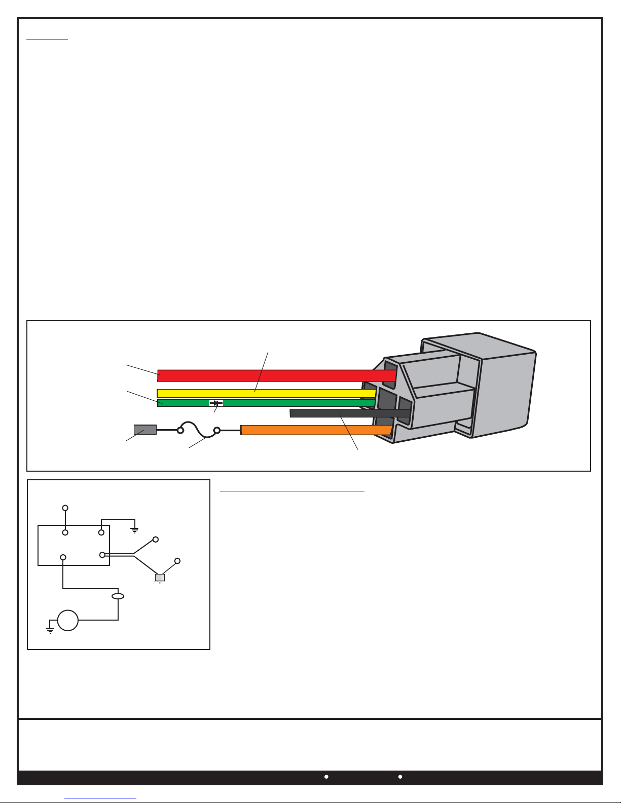
WIRING
Before starting, disconnect the Negative (-) cable on the vehicles battery.
Using the electrical connectors and wire ties provided, follow the directions below.
WARNING: When extending wires always use the identical gauge wire as provided.
See Diagrams # 8 & 9.
RELAY HARNESS
Red: Using the Blue 5/16” Ring Terminal provided attach to the Positive (+) terminal of the battery.
Black: Using the Blue #10 Ring Terminal and #10 Sheet Metal Screw provided attach to a good chassis ground (-).
Yellow Wire: Using a Blue Female Connector provided attach to EITHER of the two wires on the thermostat.
Remaining Thermostat Wire: Using a Blue Wire Tap and Blue Female Connector provided, attach the remaining Thermostat
Wire to a 12V Positive (+) switched ignition source.
Warning: Attaching this wire directly to a 12V non-switched source will allow the fan to run after the vehicle has been turned off
which could effect the vehicles battery performance.
Green (Optional): The green wire is designed to work in two different configurations. When used, this will allow the fan(s) to be
turned on regardless of the temperature of the thermostat as it simply overrides all other functions. If you choose to not use this
option disregard the wire.
1. A/C Override - Using the Blue Wire Tap provided, attach the green wire to the positive (+) lead on the air conditioning compressor.
2. Manual Switch Override - Attach the Green Wire to the manual switch NOT PROVIDED.
ELECTRIC FAN
Orange Wire: Attach to a 30 Amp fused Circuit (Fuse not included), after the fuse connection attach to the Positive Electric
Fan Lead (Fan +).
Negative Fan Wire: ,Using a Blue Ring Terminal provided attach Negative (-) electric fan lead to a good chassis ground (-).
Reattach the Negative (-) cable on the vehicles battery.
Diagram #9
Diagram #8
TROUBLE SHOOTING Q&A
Q: Why doesn’t the fan turn on?
A: 1. Check all connections to make sure all contacts are crimped correctly.
2. Check all Ground (-) connections to make sure all paint is sanded off and you
are getting a metal to metal contact.
Q: Why does the fan run after the engine is turned off?
A: Check the wire going to the Thermostat Switch, this wire should be connected to
a 12V Positive (+) switched ignition source.
Q: Why doesn’t the fan turn on when I use the Override function?
A: To quickly test the Override circuit, disconnect the Green Wire and run a jumper
wire directly to the Positive (+) terminal on the battery. The electric fan should
start immediately. If fan started, reattach the Green Wire to the proper (+) wire on
the A/C clutch or Manual Switch.
Chassis
Ground (-)
Orange
Fan
Positive (+)
30Amp Fuse
Ignition
Switch
Red
30 86
85
87
Green
Orange
Yellow
Black
Chassis
Ground (-)
12 Volt Positive (+)
Battery
Thermostat
Switch
RELAY
Override Circuit
(Optional)
FAN MOTOR
Red Wire
Battery Power
12V (+)
Black Wire
Chassis Ground (-)
Green Wire
Optional A/C
Override (+) One Way Diode
Positive (+)
Fan Lead
Yellow Wire
to 12V (+)
Switched Power
30Amp Fuse
(Not Supplied)
Table of contents
Other Derale Perfomance Fan manuals

Popular Fan manuals by other brands


Hunter
Hunter Granville Owner's guide and installation manual

Danfoss
Danfoss Air a2 user manual

Minka Group
Minka Group minkaAire CONCEPT II WET instruction manual

Flight Medical Innovations
Flight Medical Innovations Flight 60 Ventilator Operator's manual

Hyundai
Hyundai H-SF16-RC03 instruction manual

Excelsior
Excelsior Excelair EBF 30 instruction manual


