Desert Star SharkEye Use and care manual
1
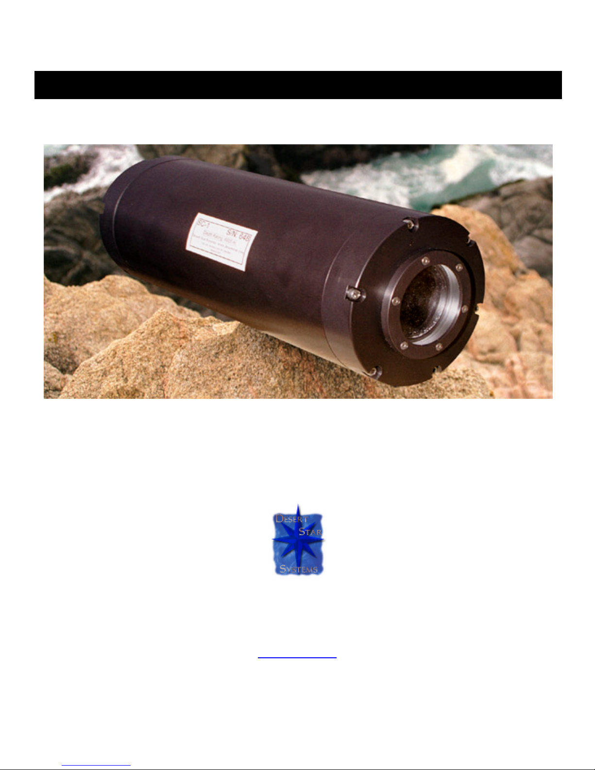
SharkEyeDigital Still Camera
Operator & Technical Reference Manual
Revision 1.22
Desert Star Systems, LLC
761 Neeson Road #9
Marina, CA 93933
(831) 384-8000 (831) 384-8062 FAX
www.desertstar.com

2
Addendum
Helpful Hints for Proper Operation
1. Choice of Operating System and Interface Cards
While the Sharkeye™ can be operated under most Microsoft operating systems,
it is STRONGLY recommended that Microsoft Windows 2000 be used. This
results in the most stable platform and least amount of installation problems,
especially with respect to the FireWire interface.
We also recommend using OrangeMicro Firewire adapters (either PCI or
PCMCIA) other cards, notable the ATI DV card can cause connection problems.
The RS-485 adapter can be used with any standard PC RS-232 port. If a true
RS-485 link is desired, we recommend the Quatech FastCOMM-422 PCI card.
We have not found any PCMCIA RS-485 adapter to work suitably, use of an RS-
232 port and the supplied adapter is recommended.
2. FireWire link and Strobe Photography
Firing of an attached strobe can cause the PC to lose a Firewire link to the
camera. It is strongly recommended that when a strobe is in use that the RS-485
link be used.
3. Out-of-Water Photography:
In order to maximize light sensitivity underwater, the Sharkeye™ camera does
not incorporate an Infrared cutoff filter in it’s optics. This will cause images
acquired out of the water to have a more yellowish cast than normal and for other
colors to be washed out. Additional processing in an image manipulation
software package (such as Adobe Photoshop) can correct some of this.

3
1. Introduction........................................................................................................................................................5
2. Unpacking...........................................................................................................................................................5
3. SharkEye™ Connectors.....................................................................................................................................5
Multi-Function Connector.....................................................................................................................................5
Umbilical Connector.............................................................................................................................................6
Strobe Connector..................................................................................................................................................6
4. SharkEye™ Cables.............................................................................................................................................6
Multi-Function Connector Adapter.......................................................................................................................6
Firewire to AMP Connector Communication Adapter..........................................................................................7
Umbilical Adapter (Optional)................................................................................................................................7
RS-485/RS-232 Converter Communication Adapter.............................................................................................8
Y-Splitter Adapter................................................................................................................................................9
Power Adapter/Charger........................................................................................................................................9
Battery Charger Connector Adapter...................................................................................................................10
5. Operating the Camera......................................................................................................................................10
5.1 Preparations For Operation..........................................................................................................................10
5.2 Activating the Camera...................................................................................................................................10
5.3 The Status LED............................................................................................................................................11
5.6 Battery Charging (optional)...........................................................................................................................11
5.7 Connecting a Strobe ......................................................................................................................................11
6. Standard Camera Operation............................................................................................................................12
6.1 Starting the SharkEye™ Desktop Application...............................................................................................12
6.2 Connecting the Camera .................................................................................................................................13
6.2.1 IEEE-1394 FireWire Connection.............................................................................................................................................................13
6.2.2 RS-485/RS-232 Connection......................................................................................................................................................................13
6.3 Acquiring Images ..........................................................................................................................................13
6.4 Resolution Control.........................................................................................................................................14
6.5 Focus Control................................................................................................................................................14
6.6 Exposure Control..........................................................................................................................................15
6.7 White-Balance Control..................................................................................................................................16
6.8 Lens Control (optional)..................................................................................................................................16
6.9 Saving Images ...............................................................................................................................................17
6.9.1 Saving Images on the PC............................................................................................................................................................................17
6.9.2 Saving Images on the Camera ...................................................................................................................................................................18
6.10 Retrieving Stored Images ............................................................................................................................18
6.11 Erasing Stored Images.................................................................................................................................19

4
6.12 Negotiating an RS-485/RS-232 Link ............................................................................................................19
7. Autonomous Camera Operation......................................................................................................................21
7.1 Scheduled Operation.....................................................................................................................................21
7.2 External Triggered Operation (Optional)......................................................................................................21
8. Camera System Maintenance...........................................................................................................................22
Appendix A. Using the FastComm PCI RS-485 Adapter..................................................................................22
Appendix B. Guidelines For SharkEyePhotography......................................................................................23

5
1. Introduction
Thank you for your purchase of the SharkEye™ digital still camera. The SharkEye™ is an extremely versatile camera that
can be configured in multiple ways. This manual describes the standard SharkEye™ and discusses some of the more
common options.
2. Unpacking
Below is a list of standard SharkEye™ components. Most systems will come with all of the following. However, customized
systems may be shipped without some of the standard components. For example a SharkEye™ not equipped with an
external FireWire interface will not include the Firewire to AMP Connector Communication Adapter.
SharkEye™ Component List
•1 ea. SharkEye™ Digital Still Camera
•3 ea. protective dummy plugs for connectors w/ locking sleeve
•1 ea. SharkEye Multi-Function Connector Adapter
•1 ea. Firewire to AMP Connector Communication Adapter
•1 ea. RS-485/RS-232 Converter Communication Adapter
•1 ea. Umbilical Adapter (optionally terminated to AMP) w/ locking sleeve
•1 ea. Y-Splitter Adapter
•1 ea. Power Adapter/Charger
•1 ea. Battery Charger Connector Adapter
•1 ea. Software Installation Disk
•This manual
In order to use your SharkEye™, you will also need a personal computer.
If a shipment is incomplete, please immediately contact Desert Star Systems. If you are missing any components required
for system operation, obtain these components before proceeding.
3. SharkEye™ Connectors
Multi-Function Connector
This connector is present on all versions of SharkEye. It is used for camera control (via RS232 or RS485), retrieval of
image data (via Firewire), and supplying external power.
Bulkhead Connector: Subconn MCBH8F
Cable Connector: Subconn MCIL8M
1: Ground
2: RS232 TXD (from SharkEye) or RS485 TX/RX+
3: RS232 RXD (to SarkEye) or RS485 TX/RX-
4: FireWire TPA+
5: FireWire TPA-
6: FireWire TPB+
7: FireWire TPB-
8: External Power Input (12V to 24V DC)
6
Umbilical Connector
Used for umbilical communication. The RS232 or RS485 interface is the same one as is available on the multi-function
connector.
Bulkhead Connector: Subconn MCBH6M
Cable Connector: Subconn MCIL6F
1: Ground
2: RS232 TXD (from SharkEye) or RS485 TX/RX+
3: RS232 RXD (to SharkEye) or RS485 TX/RX-
4: External Power Input (+8V to +25V)
5: External image capture trigger (optional)
6: External image capture GND (optional)
Strobe Connector
Used for connecting external strobe and for battery charging.
Bulkhead Connector: Subconn MCBH5F
Cable Connector: Subconn MCIL5M
1: Ground
2: Strobe Trigger (shorted to ground for trigger)
3: Strobe Quench (shorted to ground to stop strobe)
4: Battery Charge Input (24V supply through 2 Ohm/10 Watt resistor in charger)
5: Power Output for strobe (6V Standard or (optional: signal from pin4 of umbl connector))
4. SharkEye™ Cables
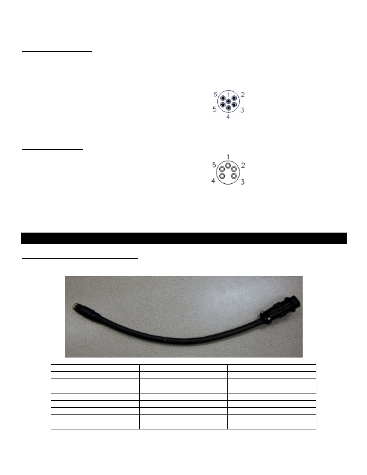
Multi-Function Connector Adapter
MCIL8M to 9-pin AMP male. Used to convert the underwater connector to an AMP connector.
Function MCIL8M 9-pin AMP male
Ground 1 4
TXD or TX/RX+ 2 2
RXD or TX/RX- 3 3
Firewire TPA+ 4 1
Firewire TPA- 5 5
Firewire TPB+ 6 8
Firewire TPB- 7 9
External Power 8 7

7
Firewire to AMP Connector Communication Adapter
Used to convert the AMP connector to a IEEE1394 standard 6 pin connector
Function IEEE1394 6-pin cable 9-pin AMP female
Power 1 (White) -
GND 2 (Black) 4
TPB- 3 (Red/Orange) 5
TPB+ 4 (Green/Blue) 1
TPA- 5 (Orange/Red) 9
TPA+ 6 (Blue/Green) 8
Umbilical Adapter (Optional)
MCIL6F to 9-pin AMP male. A MCIL6F cable can be terminated with a 9-pin AMP connector if desired. However,
normally an Unterminated whip is supplied.
Function MCIL6F 9-pin AMP male
Ground 1 4
TXD or TX/RX+ 2 2
RXD or TX/RX- 3 3
External Power Input (+8V to
+25V) 4 7
Trigger 5NA
Trigger GND 6NA
The standard SharkEye™ is delivered with a short whip that can be used to interface the camera to your
umbilical.
Unterminated Cable Color Code: 1: Black 2: White3: Red 4: Green5: Blue6: Brown
8
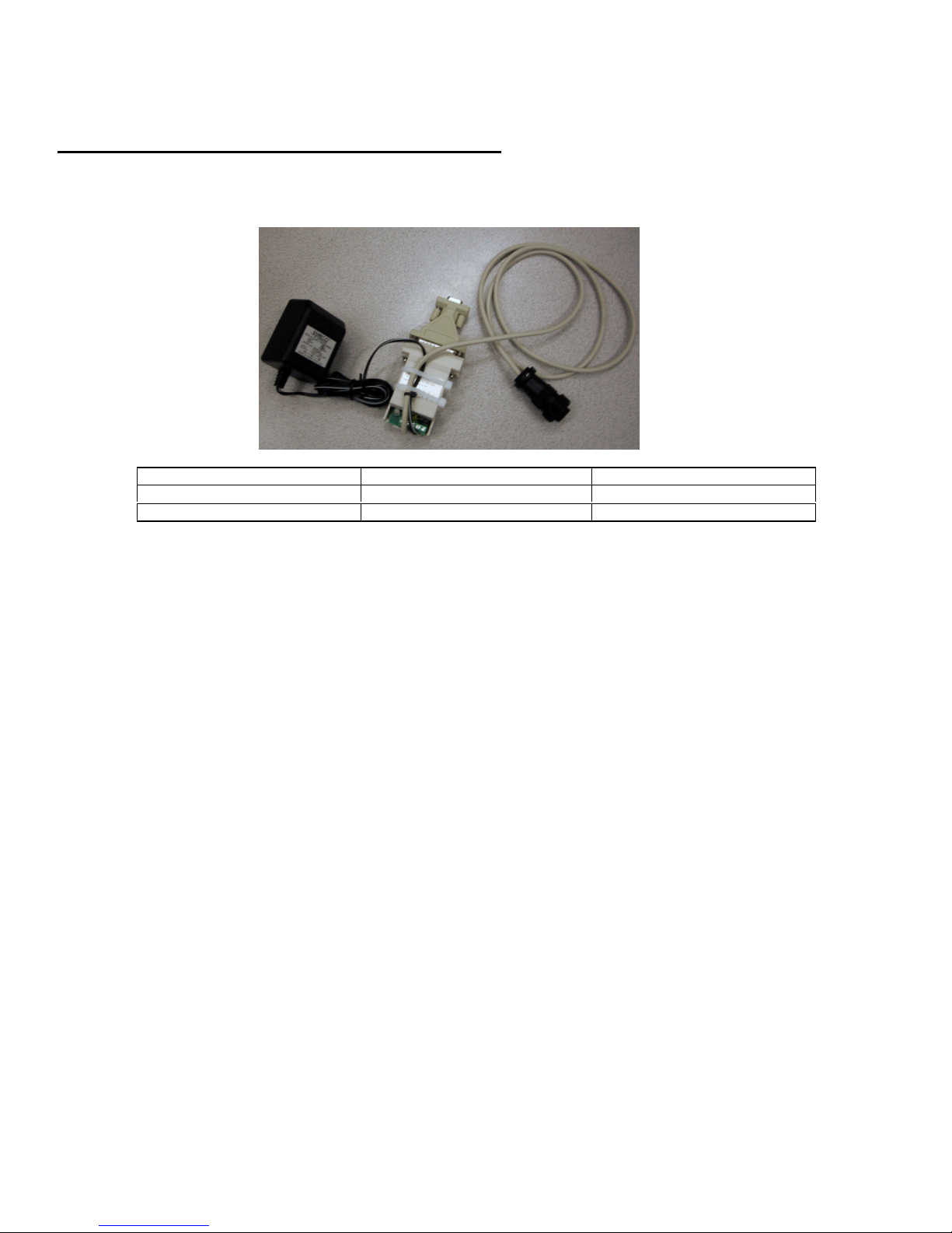
RS-485/RS-232 Converter Communication Adapter
9-Pin AMP connector to RS-485/RS-232 Converter. This converter allows for the use of a standard RS-232
communication port with the standard SharkEye™ camera.
Function 9-pin AMP female (data) RS-485/RS-232 Converter
TXD or TX/RX+ 2A
RXD or TX/RX- 3B
9
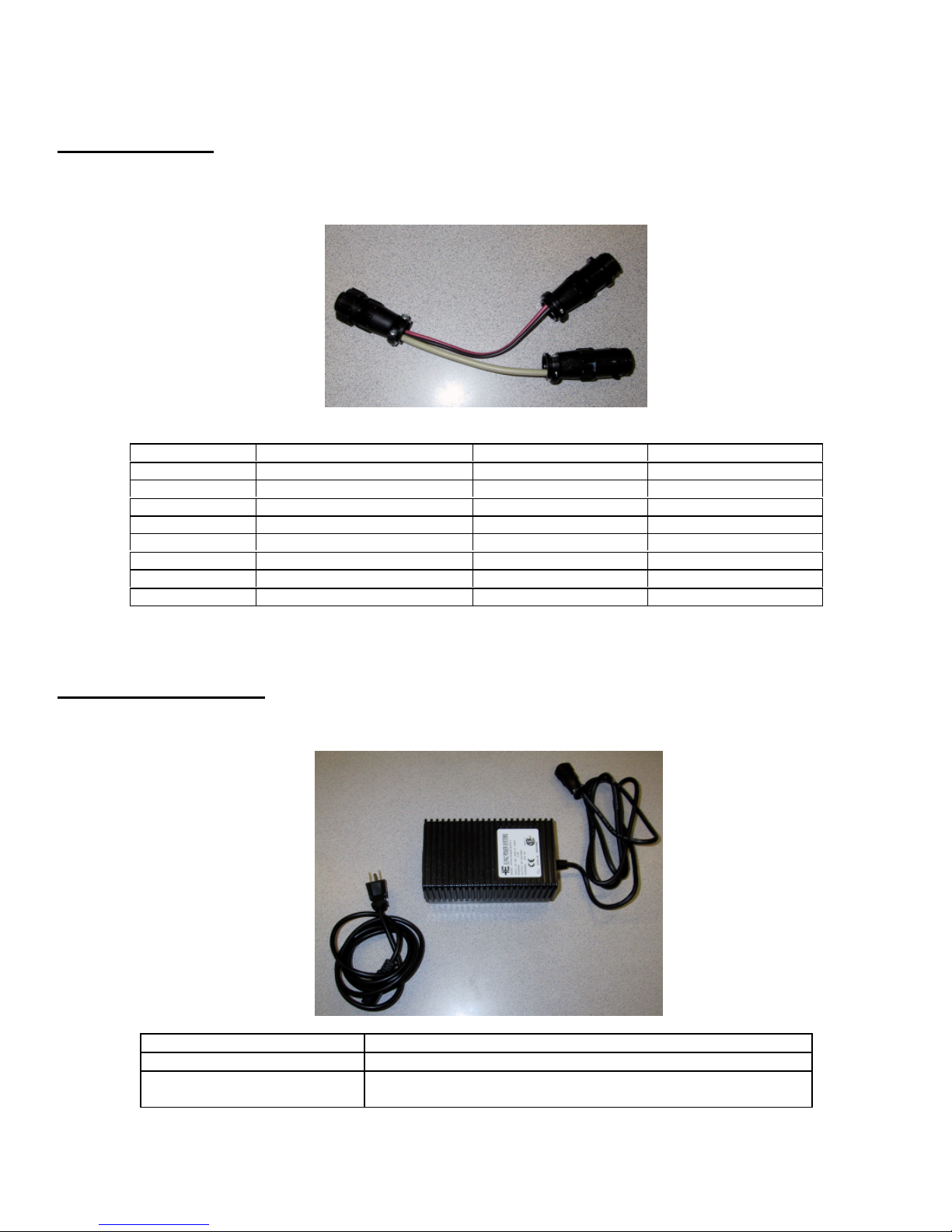
Y-Splitter Adapter
2 (power/data) 9-pin AMP male to 1 9-pin AMP female. The Y-Splitter allows for the use external power and a
communication link (IEEE1394 or RS-485) at the same time. It can be used with the Multi-function adapter or umbilical
adapter and either communication adapter.
Function 9-pin AMP male(power)
9-pin AMP male (data)
9-pin AMP female
Ground 4 4 4
TXD or TX/RX+ NA 2 2
RXD or TX/RX- NA 3 3
Firewire TPA+ NA 1 1
Firewire TPA- NA 5 5
Firewire TPB+ NA 8 8
Firewire TPB- NA 9 9
External Power 7NA 7
Note: Pin 6 of the AMP connector is not used
Power Adapter/Charger
9-Pin AMP to 110V/24V converter. The power adapter can be used to externally power the SharkEye™ or to charge any
internal batteries.
Function 9-pin AMP female(power)
Ground 4
Power (24V through 2 Ohm
Resistor) 7

10
Battery Charger Connector Adapter
MCIL5F to 9-pin AMP male. Used to connect the Power Adapter to the SharkEye™ Strobe connector in order to charge
internal batteries. Note: The AMP connector may have additional pins, which are not used in SharkEye™ applications.
Function MCIL5F 9-pin AMP male
Ground 1 4
Charge Voltage (24 Volts
through a 2 Ohm Resistor) 4 7
5. Operating the Camera
5.1 Preparations For Operation
Follow these steps to get the SharkEye™ ready for operation.
•Unpack the SharkEye™ and make sure you've got all the parts.
•Charge the internal battery if necessary.
•Connect the SharkEye™ to your computer.
•Activate and test SharkEye™ on your desktop.
•Deploy for your actual mission.
5.2 Activating the Camera
The SharkEye™ offers two 'power ON' options:
•'Permanent ON' is achieved by rotating the power knob to the ON position. In this mode, the camera will not perform
timed autonomous captures. Permanent ON is appropriate for most missions where the camera is controlled via a PC.
•''Standby' is achieved by rotating the knob to the ON position, waiting until the status LED starts blinking the ready
signal, and then moving the knob another 90 degrees to one of the positions half way between ON and OFF. The
camera will now perform scheduled autonomous acquisitions and fall asleep between captures in order to save battery
power.

11
5.3 The Status LED
Once the camera is active, observe the status LED. When first turned on the status LED will blink one second on one
second off. This indicates that the camera is starting up. After a few seconds, the LED should settle into a pattern of one
short blink every second. If you don’t see this pattern, you should reset the camera. Refer to the following table.
During battery charging the status LED will emit a short blink once every 15 seconds.
Status LED Pattern Description
LED is OFF The camera is OFF, the battery is dead or there is no
external power connected.
LED is always ON Not a valid blink pattern. A hardware problem may exist,
the battery may be discharged.
Single short blink once per second The camera is operating fine.
Fast short blink The internal batteries are low and should be recharged.
1/2 sec ON, 1/2 sec OFF The camera is starting up.
1 sec ON, 15 sec OFF Charging of internal batteries is under way.
SharkEye™ Blink Patterns
5.6 Battery Charging (optional)
The SharkEye™ camera can be equipped with up to 3 internal battery packs. The batteries can be charged using the
supplied battery charger.
•Connect the battery charger to the camera using the Battery Charger Connector adapter. The Battery Charger
Connector adapter has an AMP connector on one end and a 5 PIN male underwater connector on the other end. The
Battery Charger Connector adapter connects to the 5 PIN strobe connector on the SharkEye™ camera.
•Connect the battery charger to 110V.
•Turn on the camera. You should now observe the battery charging signal on the status LED (the LED will blink once
every 15 seconds.)
•Battery charging will take approximately 5 hours per battery pack. It is OK to leave the charger connected for extended
periods (for example overnight.)
5.7 Connecting a Strobe
A strobe can be connected to the SharkEye™ camera through the strobe connector and supplied strobe cable. The
strobe can be powered through the SharkEye™ camera or through an optional strobe internal battery. Strobe power will
be supplied when the SharkEye™ camera is running.
Turn the power knob on the strobe to the on position. The LED on the strobe will stay on when it is ready to fire.
12
6. Standard Camera Operation
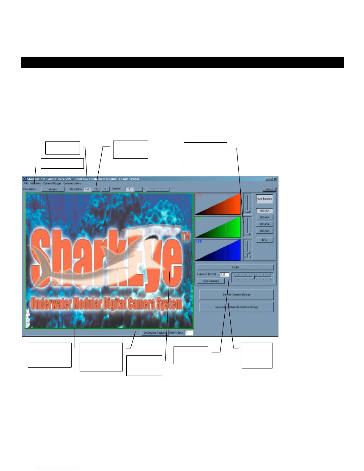
6.1 Starting the SharkEye™ Desktop Application
Select the SharkEye™ application from the windows start menu. The application will start running and indicate that it is
waiting for a connection. If the application can not open the selected serial port an error message box will appear. You
can select a different serial port to resolve this problem.
The SharkEye™ application is shown below:
Once the application has started the camera can be connected and turned on.
Title Bar Resolution
Control
Menu Bar
Histograms
and Balance
Controls
Exposure
Control
Camera
Storage
Control
Image
Upload
Progress Bar Image
Window
Interface
Status
Indicator

13
6.2 Connecting the Camera
The SharkEye™ camera can be connected through the multi-function connector or the umbilical connector. If external
power is desired the Y-splitter can be used to connect both the power supply and the communication link to the camera.
Once the camera is connected and the application has been started turn on the SharkEye™ to establish a connection.
The knob should be turned to the ON position, not the "Stand By" position.
6.2.1 IEEE-1394 FireWire Connection
If the SharkEye™ is connected to the PC via the IEEE-1394/FireWire cable the PC should automatically detect the
camera when it is turned on. When the camera has been detected the Title bar will indicate that a link has been
established. Standard operation of the SharkEye™ can now proceed.
An IEEE-1394/FireWire link requires that the SharkEye™ application software be run under MS Windows 98SE, MS
Windows 2000, or MS Windows XP (Windows 2000 is STRONGLY Recommended).
Note: If the SharkEye™ is equipped with internal hard disk storage saving images on-board the camera will be disabled
while the camera is connected to a PC through a IEEE-1394/FireWire connection.
Note: The IEEE-1394/FireWire link can be very sensitive. If the multifunction adapter is jostled the link can be
lost. If the IEEE-1394/FireWire link is inadvertently lost, it is best to reset the software, and reset the camera.
6.2.2 RS-485/RS-232 Connection
When the application is started the software will attempt to open the last used serial port at the last used baud rate. If this
port can not be opened an error message will be shown. In this case please see the chapter on Negotiating an RS-
485/RS-232 Link.
The SharkEye™ camera uses RS-485 serial communication. An RS-485/RS-232 converter is provided to allow for the
use of the SharkEye™ with a standard PC RS-232 port. The converter must be used if connection to a standard RS-232
is desired. The converter can be used with either the multi-function or umbilical ports.
Once the camera has been connected turn it on. The application will detect the camera and establish a link. When the
camera has been detected the Title bar will indicate that a link has been established. Standard operation of the
SharkEye™ can now proceed.
Note: The SharkEye™ application will not allow the retrieval of images stored on a camera internal hard disk when an
RS-485/RS-232 link is used. Retrieval of images stored on the camera internal disks can only be done using a IEEE-
1394/FireWire link.
6.3 Acquiring Images
Images are acquired by pressing the left mouse button when the cursor is anywhere in the Image Window.
The camera will acquire an image and the application will begin to download the image. The Image Upload Progress
Bar indicates the status of the image transfer to the PC. The image will be displayed when the progress bar reaches the
end.
14
While acquiring images the Interface Status Indicator will change from GREEN to RED indicating that user input is
disabled at this time. The Interface Status Indicator will return to GREEN when the application is ready for more input.
Images can also be acquired continuously by pressing the Continuous Capture button located to the right of the Image
Upload Progress Bar. The application will continuously acquire images now, pausing for the specified time between
captures. The Interface Status Indicator will change to YELLOW in between captures to indicated that camera settings
(such as exposure) can be changed.
6.4 Resolution Control
Pressing the desired resolution button on the top of the screen can change the resolution of the image uploaded to the
PC. Resolutions can be set to ¼, ½ or full resolution. The lower the resolution the quicker the image can be uploaded to
the PC.
NOTE: The camera will always save full resolution images to it’s internal storage. The resolution controls only modify the
size of the image uploaded to the PC.
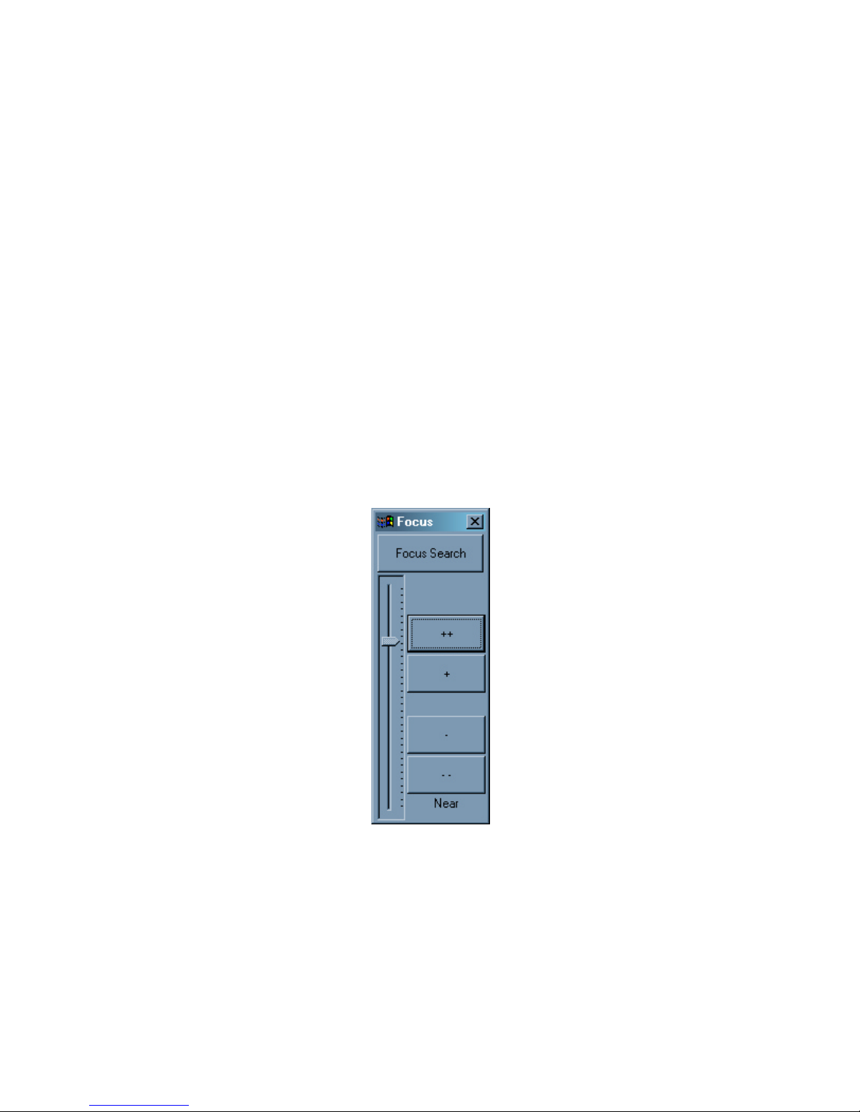
6.5 Focus Control
The internal focus control dialog can be displayed by pressing the Focusbutton at the top right of the application window.
The Focus Dialog is shown below:
The Focus Indicator, the sliding scale on the left of the dialog, shows where the focus is set in it’s range of motion.
There are 5 buttons on this dialog.
The Focus Search button attempts to find the current optimal focus. Pressing this button causes the camera to search
it's entire focus range for the image that has the focus in the center of the image. A progress bar will appear while the
camera is searching for focus.
It is possible that the camera can not determine a reasonable focus. Too dark a scene or a poor scene at the center of an
image can cause this. An example of a poor scene is a blank wall or a bare sandy sea floor where there is little contrast.

15
Focus can also be controlled automatically using the other four buttons. The ++ will change the focus to further away in
large steps, the +will do the same in the smallest possible increments. The --, and –buttons do the same but move the
focus closer to the camera.
6.6 Exposure Control
Exposure is controlled through the Exposure Control Panel on the main screen. The Exposure Control Panel is shown
below:
Exposure time can be set by moving the slider on the panel or by entering an exposure time in the edit box. Exposure
times are entered in 1/sec units, the screen above shows an exposure time of 1/5.26 seconds. Exposure times greater
than 1 second can be selected using the slider or entered in the edit box. When entered in the edit box the time must be
specified with a trailing lower case 's' (for example entering 2s in the edit box will select a 2-second exposure time.)
Pressing the Auto Exposure button can enable auto exposure. When auto exposure is enabled the camera will
automatically attempt to find the best exposure for each image capture. The Auto Exposure algorithm only looks at the
center 128x128 pixels of the image, so it is possible that while the exposure of the center of the scene will be optimum,
the overall image exposure will not. In this case it is best to use the result provide by the Auto Exposure as a starting
point and then manually adjust the exposure for best results.
Auto Exposure will only work for exposure times between 1/1000 second and 1/3 second. Also, Auto Exposure will not
operate when strobe mode is enabled.
Pressing the Strobe button on the Exposure Control Panel enables strobe mode. The Strobe Control Panel will
replace the Exposure Control Panel when the strobe is enabled. The Strobe Control Panel is shown below:
The strobe power can be adjusted using the slider at the bottom of the panel. The strobe power can be adjusted to values
between 0 and 100%
Pressing the Strobe button again will return to non-strobe mode and the Exposure Control Panel will be displayed
again.

16
6.7 White-Balance Control
The White-Balance Control is used to adjust the gains of the individual color channels to correct for variations in the
color of scene illumination. The White-Balance Control is shown below:
The histograms give a graphic illustration of the spectrum of the image, showing what and how often specific colors
appear in an image. The mean of the histogram is displayed textual and as a white vertical line on the histogram. In a
well-balanced image of a white scene the histogram means should all be the same.
Pressing the Auto Balance button enables Auto White-Balance. Auto White-Balance modifies the individual color
channel gains to attempt to insure that the means of the histograms are all equal, thus insuring a well-balanced image.
The individual channel gains can be manual adjusted using the sliders on the White-Balance Control.
White Balance Control Panel
There are also 4 Simulated Film Speed buttons on the control. These buttons change the baseline gain on all color
channels to simulate a change in film speed. Increasing the simulated film speed increases the sensitivity of the camera,
but can cause increased noise in the image.
The B/W button tells the SharkEye™ application that an optional black and white image sensor is being used rather than
then standard color sensor.
6.8 Lens Control (optional)
The Lens Control Dialog can be displayed by selecting Windows/Lens Control from the main menu bar. The Lens
Control Dialog allows for the control of an optional motorized zoom lens in the SharkEye™ camera. The top row of
buttons controls the zoom of the lens. Pressing one of these buttons can set the focal length. The bottom row of buttons
controls the aperture of the lens. Pressing one of these buttons can set the f-stop of the lens.
Note: Lens control only works on SharkEye™ cameras equipped with a motorized zoom lens.
Histograms Gain Sliders
Auto-balance
Simulated
Film Speed

17
Lens Control Dialog
6.9 Saving Images
6.9.1 Saving Images on the PC
Images can be saved on the PC in several ways. Images saved on the PC are saved in the image directory. The image
directory can be set through the Settings Dialog, which is displayed by selecting Windows/Settings from the main menu.
Enter the desired directory or press the browse button and select a directory from the file browser.
Selecting Save All Captureswill cause ALL images acquired to be saved to the PC.
Entering a mission name on the main window can further modify the image directory. All images will then be saved to a
sub-directory with the mission name in the Image directory.
In addition to selecting Save All Captures, individual images can be saved on the PC by selecting File/Save Image from
the main menu bar.
Pressing the right mouse button while the cursor is anywhere in the image window can save an annotated image. The
annotation window will pop up. Selecting an annotation in the list box will save an image annotated with the selected
string. An additional annotation string can also be entered into the edit box on the annotation window. Pressing enter in
the edit box will also save an annotated image. The standard operating procedure is to enter any desired information in
the edit box and then select the desired annotation in the list box.
The image annotations can be modified by editing or creating the text file annotation_cnf.txt in the SharkEye™ directory
(C:\Program Files\Desertstar\SharkEye is the default) This file can be modified in any text editor, such as notepad. Below
is an example annotation_cnf.txt file.

18
cm clam
bm biomat
bf big fish
bff big fin fish
dv diver
sub submarine Example annotation_cnf.txt file.
The format for each line is : “AAA Annotation Text String” where AAA is the annotation added to the image file name,
which can be up to 3 characters, and Annotation Text String is a description that will show up in the annotation window.
6.9.2 Saving Images on the Camera
Images can also be saved on board the camera. This is useful when there is only a slow communication link between the
PC and the camera.
Pressing the Save to Camera Storage button on the main window to save a FULL resolution image to either the on-
board hard disk or FLASH memory. Selecting Save all Images to Camera Storage will save every image acquisition to
on-board storage.
Note: If the SharkEye™ camera is not equipped with a hard disk, the on-board image storage can be filled quickly. 128
MB of FLASH storage will hold 64 images.
Images stored on board the camera can be retrieved using the Image Retrieval Dialog, which is accessed by selecting
Camera Storage/Get Imagesfrom the main menu.
6.10 Retrieving Stored Images
Selecting Camera Storage/Get Images from the main menu displays the Image Download Dialog. Pressing the
download button will initiate the retrieval of saved images. These images will be shown in the window on the right of the
dialog and saved on the PC. The progress bar at the top of the screen illustrates how far along the process is.
The desired image range can be entered into the edit box at the bottom of the screen.
Checking the Supervised box will force the user to accept each image as it is retrieved from the camera. This can be
used if the data link to the camera is not robust.

19
Note: Images saved on internal hard disks can only be retrieved when an IEEE-1394/FireWire link is used.
6.11 Erasing Stored Images
Images stored on the camera can be deleted by selecting Camera Storage/Erase Storage from the main menu. This will
erase either the camera internal hard disk or FLASH memory. This will permanently delete the images, images can not
be undeleted.
Note: Internal hard disks can only be deleted when an IEEE-1394/FireWire link is used.
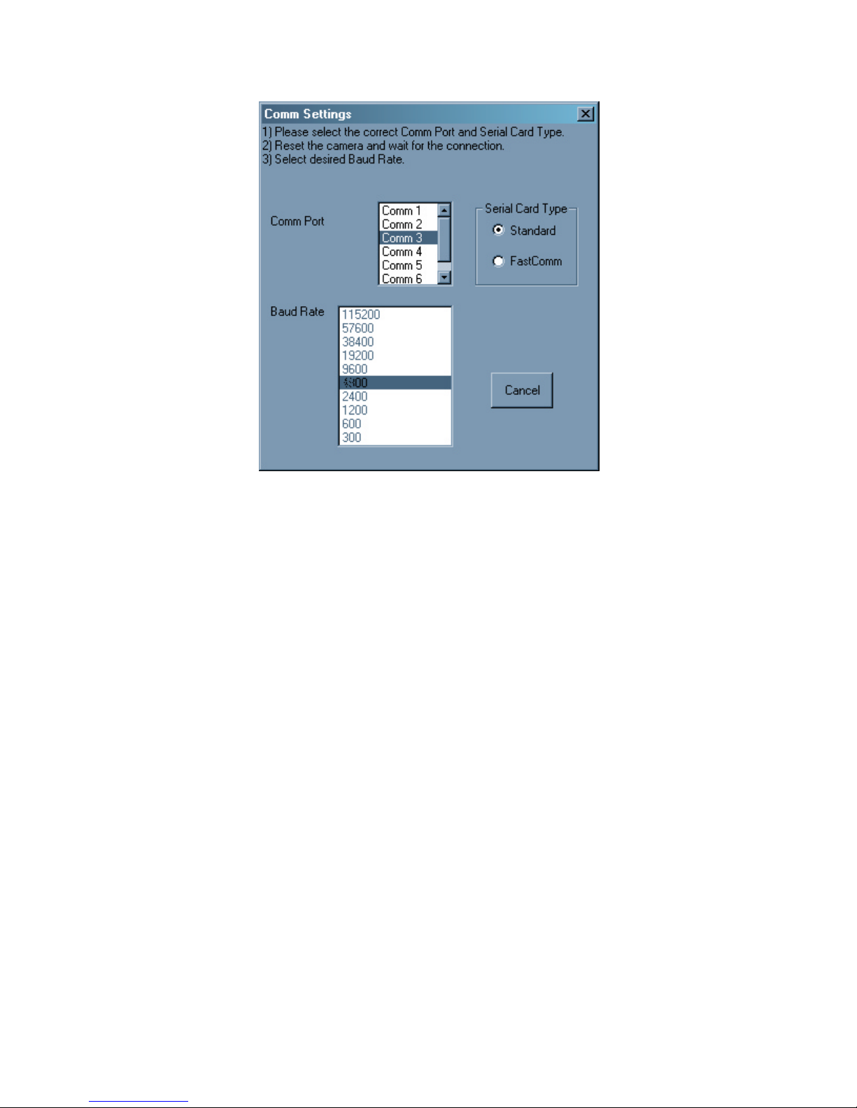
6.12 Negotiating an RS-485/RS-232 Link
A new baud rate or Comm port can be selected through the Comm Settings dialog. This window is displayed by
selecting Communications/Comm Settingsfrom the main menu.
When the window pops-up select the desired Comm port and type, (See the appendix on configuring a Quatech
FastComm card if one is being used.) The default baud rate (4800 baud) will be automatically selected. Turn on the
camera and wait about 60 seconds. The application should detect a link and a notification box will pop-up. The new
desired baud rate can now be selected. A negotiated communication link will then be attempted. If it is successful a
notification box will be displayed and standard operations can commence. If the negotiated link is not successful, reset
the camera and try again possibly at a slower speed.
20
The last successful negotiated link will be used next time the application is started.
Table of contents


