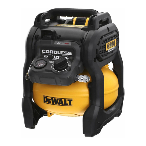
DeWalt DCC2560 User manual

Specifications
Model DCC2560
Weight 21.5 Lbs. (9.75 Kg)
Height 15.5" (393.7 mm)
Width 12.5" (317.5 mm)
Length 14.0" (355.6 mm)
Air tank capacity 2.5 Gallon (9.5 Liters)
Approx cut-in pressure 105 Psi
Approx. Cut-out pressure 135 Psi
Scfm @ 90 psi 1.2 **
Noise level 79.0 DBA+
Fuse type Time delay
Regulated pressure rating (approximate) 0–135 Psi
Quick connect type 1/4" (6.4 mm) industrial
Pump Type Oilless
**Tested per iso 1217:1996
+Tested per iso 3744:1994
Manual
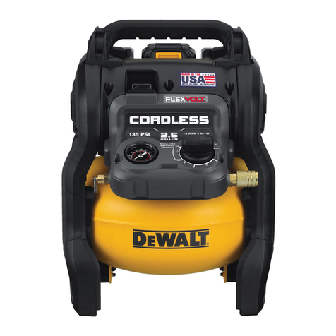
DCC2560
60V Max* 2.5 Gallon Cordless AirCompressor

English (original instructions)
Definitions: Safety Alert Symbols and Words
This instruction manual uses the following safety alert symbols and words to alert you to hazardous situations and your risk
of personal injury or property damage.
DANGER: Indicates an imminently hazardous situation which, if not avoided, will result in death or seriousinjury.
WARNING: Indicates a potentially hazardous situation which, if not avoided, could result in death or seriousinjury.
CAUTION: Indicates a potentially hazardous situation which, if not avoided, may result in minor or moderateinjury.
(Used without word) Indicates a safety related message.
NOTICE: Indicates a practice not related to personal injury which, if not avoided, may result in propertydamage.
WARNING! Read all safety warnings and all
instructions. Failure to follow the warnings and
instructions may result in electric shock, fire and/or
seriousinjury.
WARNING: To reduce the risk of injury, read the
instructionmanual.
1 Auto On/Off switch
2 Battery
3 Battery release button
4 Safety valve
5 Tank pressure gauge
6 One-turn regulator
7 Drain valve
8 Check valve
9 Quick-connect coupler
10 Carry handle
11 Tank
Fig. A
FRONT BACK
10
6
5
1
4 9
7
11
23
8

SAVE ALL WARNINGS AND
INSTRUCTIONS FOR FUTURE
REFERENCE
DANGER: RISK OF EXPLOSION OR FIRE
What can happen How to prevent it
It is normal for electrical contacts
within the motor and pressure
switch to spark.
Always operate the compressor
in a well ventilated area free of
combustible materials, gasoline, or
solvent vapors.
If electrical sparks from compressor
come into contact with flammable
vapors, they may ignite, causing
fire or explosion.
If spraying flammable materials,
locate compressor at least 20 feet
(6.1 m) away from spray area.
An additional length of hose may
be required.
Store flammable materials
in a secure location away
from compressor.
Restricting any of the compressor
ventilation openings will cause
serious overheating and could
cause fire.
Never place objects against or on
top of compressor pump.
Operate compressor in an open
area at least 12" (30.5 cm) away
from any wall or obstruction that
would restrict the flow of fresh air
to the ventilation openings.
Operate compressor in a clean,
dry well ventilated area. Do not
operate unit indoors or in any
confined area.
Unattended operation of this
product could result in personal
injury or property damage.
To reduce the risk of fire, do
not allow the compressor to
operate unattended.
Always remain in attendance with
the product when it is operating.
Always turn off and unplug unit
when not in use.
CAUTION: RISK FROM NOISE
What can happen How to prevent it
Under some conditions and
duration of use, noise from
this product may contribute to
hearing loss.
Always wear certified safety
equipment: ANSI S12.6 (S3.19)
hearing protection.
DANGER: RISK TO BREATHING
(Asphyxiation)
What can happen How to prevent it
The compressed air directly from
your compressor is not safe for
breathing. The air stream may
contain carbon monoxide, toxic
vapors, or solid particles from
the air tank. Breathing these
contaminant's can cause serious
injury or death.
Air obtained directly from the
compressor should never be
used to supply air for human
consumption. In order to use air
produced by this compressor for
breathing, suitable filters and
in-line safety equipment must be
properly installed. In-line filters
and safety equipment used in
conjunction with the compressor
must be capable of treating air
to all applicable local and federal
codes prior to human consumption.
Sprayed materials such as paint,
paint solvents, paint remover,
insecticides, weed killers,
may contain harmful vapors
and poisons.
Work in an area with good cross
ventilation. Read and follow the
safety instructions provided on the
label or safety data sheets for the
materials you are spraying. Always
use certified safety equipment:
OSHA/MSHA/NIOSH respiratory
protection designed for use with
your specific application.
WARNING: RISK OF BURSTING
Air Tank: The air tank on your Air Compressor is designed (for units
with air tanks greater than 6 inch / 152 mm diameter) according to
ASME Section VIII, Div. 1 rules. All pressure vessels should be inspected
once every two years.
The following conditions could lead to a weakening of the air tank, and
result in a violent air tank explosion:
What can happen How to prevent it
Failure to properly drain condensed
water from air tank, causing rust
and thinning of the steel air tank.
Drain air tank daily or after each
use. If air tank develops a leak,
replace it immediately with
a new air tank or replace the
entire compressor.
Modifications or attempted repairs
to the air tank.
Never drill into, weld, or make
any modifications to the air tank
or its attachments. Never attempt
to repair a damaged or leaking air
tank. Replace with a new air tank.
Unauthorized modifications to
the safety valve or any other
components which control air
tank pressure.
The air tank is designed to
withstand specific operating
pressures. Never make adjustments
or parts substitutions to alter the
factory set operating pressures.
Attachments & accessories:

Exceeding the pressure rating of
air tools, spray guns, air operated
accessories, tires, and other
inflatables can cause them to
explode or fly apart, and could
result in serious injury.
Follow the equipment
manufacturers recommendation
and never exceed the maximum
allowable pressure rating of
attachments. Never use compressor
to inflate small low pressure
objects such as children’s toys,
footballs, basketballs, etc.
Tires:
Over inflation of tires could
result in serious injury and
property damage.
Use a tire pressure gauge to check
the tires pressure before each
use and while inflating tires; see
the tire sidewall for the correct
tire pressure.
NOTE: Air tanks, compressors
and similar equipment used to
inflate tires can fill small tires
similar to these very rapidly. Adjust
pressure regulator on air supply
to no more than the rating of the
tire pressure. Add air in small
increments and frequently use the
tire gauge to prevent over inflation.
WARNING: RISK OF ELECTRICAL SHOCK
What can happen How to prevent it
Your air compressor is powered
by a battery. Like any other direct
current powered device, if it is
not used properly it may cause
electric shock.
Never operate the compressor
outdoors when it is raining or in
wet conditions.
Never operate compressor with
protective covers removed
or damaged.
Repairs attempted by unqualified
personnel can result in serious
injury or death by electrocution.
Any electrical wiring or repairs
required on this product should
be performed by a D
e
WALT
factory service center or a D
e
WALT
authorized service center in
accordance with national and local
electrical codes.
WARNING: RISK FROM FLYING OBJECTS
What can happen How to prevent it
The compressed air stream can
cause soft tissue damage to
exposed skin and can propel
dirt, chips, loose particles, and
small objects at high speed,
resulting in property damage or
personal injury.
Always wear certified safety
equipment: ANSI Z87.1 eye
protection (CAN/CSA Z94.3)
with side shields when using
the compressor.
Never point any nozzle or sprayer
toward any part of the body or at
other people or animals.
Always turn the compressor off and
bleed pressure from the air hose
and air tank before attempting
maintenance, attaching tools
or accessories.
WARNING: RISK OF HOT SURFACES
What can happen How to prevent it
Touching exposed metal such as
the compressor head, engine head,
engine exhaust or outlet tubes, can
result in serious burns.
Never touch any exposed metal
parts on compressor during or
immediately after operation.
Compressor will remain hot for
several minutes after operation.
Do not reach around protective
shrouds or attempt maintenance
until unit has been allowed to cool.
WARNING: RISK FROM MOVING PARTS
What can happen How to prevent it
Moving parts such as fans and
connecting rods can cause serious
injury if they come into contact
with you or your clothing.
Never operate the compressor
with guards or covers which are
damaged or removed
Keep your hair, clothing, and
gloves away from moving parts.
Loose clothes, jewelry, or long hair
can be caught in moving parts.
Air vents may cover moving parts
and should be avoided as well.
Attempting to operate compressor
with damaged or missing parts or
attempting to repair compressor
with protective shrouds removed
can expose you to moving parts
and can result in serious injury.
Any repairs required on this
product should be performed by a
D
e
WALT factory service center or a
D
e
WALT authorized service center.
WARNING: RISK OF UNSAFE OPERATION
What can happen How to prevent it
Unsafe operation of your air
compressor could lead to serious
injury or death to you or others.
Review and understand all
instructions and warnings in
this manual.
Become familiar with the operation
and controls of the air compressor.
Keep operating area clear of all
persons, pets, and obstacles.
Keep children away from the air
compressor at all times.
Do not operate the product when
fatigued or under the influence
of alcohol or drugs. Stay alert at
all times.
Never modify or defeat the safety
features of this product.
Equip area of operation with a
fire extinguisher.
Do not operate machine
with missing, broken, or
unauthorized parts.
Never stand on the compressor.
WARNING: RISK OF FALLING
What can happen How to prevent it
A portable compressor can fall
from a table, workbench, or roof
causing damage to the compressor
and could result in serious injury or
death to the operator.
Always operate compressor in a
stable secure position to prevent
accidental movement of the unit.
Never operate compressor on a
roof or other elevated position.
Use additional air hose to reach
high locations.
SAVE THESE INSTRUCTIONS FOR
FUTURE USE
WARNING: This product can expose you to chemicals
including lead which is known to the State of
California to cause cancer and birth defects or other
reproductive harm.
WARNING: Some dust created by power sanding,
sawing, grinding, drilling, and other construction
activities contains chemicals known to the State
of California to cause cancer, birth defects or
other reproductive harm. Some examples of these
chemicals are:
•lead from lead-based paints,
•crystalline silica from bricks and cement and other
masonry products, and
•arsenic and chromium from chemically-
treatedlumber.
Your risk from these exposures varies, depending on how
often you do this type of work. To reduce your exposure to
these chemicals: work in a well ventilated area, and work with
approved safety equipment, such as those dust masks that are
specially designed to filter out microscopicparticles.
•Avoid prolonged contact with dust from power
sanding, sawing, grinding, drilling, and other
construction activities. Wear protective clothing and
wash exposed areas with soap and water. Allowing
dust to get into your mouth, eyes, or lay on the skin may
promote absorption of harmfulchemicals.
WARNING: Use of this tool can generate and/
or disperse dust, which may cause serious and
permanent respiratory or other injury. Always use
NIOSH/OSHA approved respiratory protection
appropriate for the dust exposure. Direct particles
away from face andbody.
The label on your tool may include the following symbols. The
symbols and their definitions are asfollows:
V.........................volts
Hz .......................hertz
min.....................minutes
or DC......direct current
......................Class I Construction
(grounded)
…/min..............per minute
BPM....................beats per minute
IPM.....................impacts per minute
RPM....................revolutions per
minute
sfpm ...................surface feet per
minute
SPM....................strokes per minute
A.........................amperes
W........................watts
or AC........... alternating current
or AC/DC....alternating or
direct current
......................Class II
Construction
(double insulated)
no.......................no load speed
n.........................rated speed
......................earthing terminal
.....................safety alert symbol
.....................visible radiation
.....................wear respiratory
protection
.....................wear eye
protection
.....................wear hearing
protection
.....................read all
documentation
BATTERIES AND CHARGERS
The battery pack is not fully charged out of the carton.
Before using the battery pack and charger, read the
safety instructions below and then follow charging
proceduresoutlined. When ordering replacement battery
packs, be sure to include the catalog number andvoltage.
Your tool uses a
DeWALT
charger. Be sure to read all safety
instructions before using your charger. Consult the chart
at the end of this manual for compatibility of chargers and
batterypacks.
READ ALL INSTRUCTIONS
Important Safety Instructions for All
Battery Packs
WARNING: Read all safety warnings and all
instructions for the battery pack, charger and
power tool. Failure to follow the warnings and
instructions may result in electric shock, fire and/
or seriousinjury.
•Do not charge or use the battery pack in explosive
atmospheres, such as in the presence of flammable
liquids, gases or dust. Inserting or removing the battery
pack from the charger may ignite the dust orfumes.
•NEVER force the battery pack into the charger. DO
NOT modify the battery pack in any way to fit into
a non-compatible charger as battery pack may
rupture causing serious personal injury. Consult
the chart at the end of this manual for compatibility of
batteries andchargers.
•Charge the battery packs only in designated
DeWALT
chargers.
•DO NOT splash or immerse in water or otherliquids.
•Do not store or use the tool and battery pack in
locations where the temperature may reach or
exceed 104°F (40°C) (such as outside sheds or metal
buildings in summer). For best life store battery packs in
a cool, drylocation.
NOTE: Do not store the battery packs in a tool with
the trigger switch locked on. Never tape the trigger
switch in the ONposition.
•Do not incinerate the battery pack even if it is
severely damaged or is completely worn out. The
battery pack can explode in a fire. Toxic fumes and
materials are created when lithium ion battery packs
areburned.

•If battery contents come into contact with the skin,
immediately wash area with mild soap and water. If
battery liquid gets into the eye, rinse water over the open
eye for 15 minutes or until irritation ceases. If medical
attention is needed, the battery electrolyte is composed of
a mixture of liquid organic carbonates and lithiumsalts.
•Contents of opened battery cells may cause
respiratory irritation. Provide fresh air. If symptoms
persist, seek medicalattention.
WARNING: Burn hazard. Battery liquid may be
flammable if exposed to spark orflame.
WARNING: Fire hazard. Never attempt to open the
battery pack for any reason. If the battery pack case
is cracked or damaged, do not insert into the charger.
Do not crush, drop or damage the battery pack. Do
not use a battery pack or charger that has received a
sharp blow, been dropped, run over or damaged in
any way (e.g., pierced with a nail, hit with a hammer,
stepped on). Damaged battery packs should be
returned to the service center forrecycling.
Transportation
WARNING: Fire hazard. Do not store or carry the
battery pack so that metal objects can contact
exposed battery terminals. For example, do
not place the battery pack in aprons, pockets, tool
boxes, product kit boxes, drawers, etc., with loose
nails, screws, keys, etc. Transporting batteries
can possibly cause fires if the battery terminals
inadvertently come in contact with conductive
materials such as keys, coins, hand tools and the
like. The US Department of Transportation Hazardous
Material Regulations (HMR) actually prohibit
transporting batteries in commerce or on airplanes in
carry-on baggage UNLESS they are properly protected
from short circuits. So when transporting individual
battery packs, make sure that the battery terminals
are protected and well insulated from materials that
could contact them and cause a shortcircuit.
Shipping the
DeWALT
FLEXVOLT™ Battery
The D
e
WALT FLEXVOLT™ battery has two modes: Use and
Shipping.
Use Mode: When the FLEXVOLT™ battery stands alone or is
in a D
e
WALT 20V Max* product, it will operate as a 20V Max*
battery. When the FLEXVOLT™ battery is in a 60V Max* or a
120V Max* (two 60V Max* batteries) product, it will operate
as a 60V Max* battery.
Shipping Mode: When
the cap is attached to the
FLEXVOLT™ battery, the
battery is in Shipping Mode.
Strings of cells are electrically
disconnected within the pack resulting in three batteries
with a lower Watt hour (Wh) rating as compared to one
battery with a higher Watt hour rating. This increased
quantity of three batteries with the lower Watt hour rating
can exempt the pack from certain shipping regulations that
are imposed upon the higher Watt hourbatteries.
USE: 120 Wh Shipping: 3 x 40 Wh
The battery label indicates two Watt hour ratings (see
example). Depending on how the battery is shipped, the
appropriate Watt hour rating must be used to determine
the applicable shipping requirements. If utilizing the
shipping cap, the pack will be considered 3 batteries at
the Watt hour rating indicated for “Shipping”. If shipping
without the cap or in a tool, the pack will be considered one
battery at the Watt hour rating indicated next to “Use”.
Example of Use and Shipping Label Marking
For example, Shipping Wh rating might indicate 3 x 40 Wh,
meaning 3 batteries of 40 Watt hours each. The Use Wh
rating might indicate 120 Wh (1 battery implied).
Fuel Gauge Battery Packs (Fig. B)
Some
DeWALT
battery packs include a fuel gauge which
consists of three green LED lights that indicate the level of
charge remaining in the batterypack.
The fuel gauge is an indication of approximate levels of
charge remaining in the battery pack according to the
followingindicators:
75–100% charged
51–74% charged
< 50% charged
Pack needs to be charged
To actuate the fuel gauge, press and hold the fuel gauge
button. A combination of the three green LED lights will
illuminate designating the level of charge left. When the
level of charge in the battery is below the usable limit, the
fuel gauge will not illuminate and the battery will need to
berecharged.
Fig. B
NOTE: The fuel gauge is only an indication of the charge left
on the battery pack. It does not indicate tool functionality
and is subject to variation based on product components,
temperature and end-userapplication.
The RBRC® Seal
The RBRC® (Rechargeable Battery
Recycling Corporation) Seal on the nickel
cadmium, nickel metal hydride or lithium-
ion batteries (or battery packs) indicates
that the costs to recycle these batteries
(or battery packs) at the end of their useful life have already
been paid by DeWALT. In some areas, it is illegal to place
spent nickel cadmium, nickel metal hydride or lithium-ion
batteries in the trash or municipal solid waste stream and

the Call2Recycle® program provides an environmentally
conscious alternative.
Call 2 Recycle, Inc., in cooperation with DeWALT and other
battery users, has established the program in the United
States and Canada to facilitate the collection of spent nickel
cadmium, nickel metal hydride or lithium-ion batteries. Help
protect our environment and conserve natural resources by
returning the spent nickel cadmium, nickel metal hydride
or lithium-ion batteries to an authorized DeWALT service
center or to your local retailer for recycling. You may also
contact your local recycling center for information on
where to drop off the spent battery. RBRC® is a registered
trademark of Call 2 Recycle,Inc.
Important Safety Instructions for All
Battery Chargers
WARNING: Read all safety warnings and all
instructions for the battery pack, charger and
power tool. Failure to follow the warnings and
instructions may result in electric shock, fire and/
or seriousinjury.
•DO NOT attempt to charge the battery pack with
any chargers other than the ones in this manual.
The charger and battery pack are specifically designed to
worktogether.
•These chargers are not intended for any uses other
than charging
DeWALT
rechargeable batteries.
Any other uses may result in risk of fire, electric shock
orelectrocution.
•Do not expose the charger to rain orsnow.
•Pull by the plug rather than the cord when
disconnecting the charger. This will reduce the risk of
damage to the electric plug andcord.
•Make sure that the cord is located so that it will not
be stepped on, tripped over or otherwise subjected
to damage orstress.
•Do not use an extension cord unless it is absolutely
necessary. Use of improper extension cord could result in
risk of fire, electric shock orelectrocution.
•When operating a charger outdoors, always provide
a dry location and use an extension cord suitable
for outdoor use. Use of a cord suitable for outdoor use
reduces the risk of electricshock.
•An extension cord must have adequate wire size
(AWG or American Wire Gauge) for safety. The smaller
the gauge number of the wire, the greater the capacity
of the cable, that is, 16 gauge has more capacity than 18
gauge. An undersized cord will cause a drop in line voltage
resulting in loss of power and overheating. When using
more than one extension to make up the total length,
be sure each individual extension contains at least the
minimum wire size. The following table shows the correct
size to use depending on cord length and nameplate
ampere rating. If in doubt, use the next heavier gauge. The
lower the gauge number, the heavier thecord.
Minimum Gauge for Cord Sets
Volts Total Length of Cord in Feet (meters)
120 V 25 (7.6) 50 (15.2) 100 (30.5) 150 (45.7)
240 V 50 (15.2) 100 (30.5) 200 (61.0) 300 (91.4)
Ampere Rating
American Wire Gauge
More
Than
Not
More
Than
0 6 18 16 16 14
610 18 16 14 12
10 12 16 16 14 12
12 16 14 12 Not Recommended
•Do not place any object on top of the charger or
place the charger on a soft surface that might block
the ventilation slots and result in excessive internal
heat. Place the charger in a position away from any heat
source. The charger is ventilated through slots in the top
and the bottom of thehousing.
•Do not operate the charger with a damaged cord
orplug.
•Do not operate the charger if it has received a sharp
blow, been dropped or otherwise damaged in any
way. Take it to an authorized servicecenter.
•Do not disassemble the charger; take it to an
authorized service center when service or repair
is required. Incorrect reassembly may result in a risk of
electric shock, electrocution orfire.
•Disconnect the charger from the outlet before
attempting any cleaning. This will reduce the risk of
electric shock. Removing the battery pack will not reduce
thisrisk.
•NEVER attempt to connect 2 chargerstogether.
•The charger is designed to operate on standard
120V household electrical power. Do not attempt to
use it on any other voltage. This does not apply to the
vehicularcharger.
WARNING: Shock hazard. Do not allow any liquid to
get inside the charger. Electric shock mayresult.
WARNING:Burn hazard. Do not submerge the
battery pack in any liquid or allow any liquid to
enter the battery pack. Never attempt to open the
battery pack for any reason. If the plastic housing of
the battery pack breaks or cracks, return to a service
center forrecycling.
CAUTION: Burn hazard. To reduce the risk of injury,
charge only
DeWALT
rechargeable battery packs.
Other types of batteries may overheat and burst
resulting in personal injury and propertydamage.
NOTICE: Under certain conditions, with the charger
plugged into the power supply, the charger can
be shorted by foreign material. Foreign materials
of a conductive nature, such as, but not limited to,
grinding dust, metal chips, steel wool, aluminum
foil or any buildup of metallic particles should be
kept away from the charger cavities. Always unplug
the charger from the power supply when there is no
battery pack in the cavity. Unplug the charger before
attempting toclean.

Wireless Certifications and Safety
Information
•This device is CAN ICES-3(B)/NMB-3(B)compliant.
•This device complies with Part 15 of the FCC rules and
Industry Canada License-exempt RSS standard(s).
Operation is subject to the following two conditions:
ʵ This device may not cause harmful interference, and
ʵ This device must accept any interference
received, including interference that may cause
undesiredoperation.
This equipment has been tested and found to comply
with the limits for a Class B digital device, pursuant to Part
15 of the FCC Rules. These limits are designed to provide
reasonable protection against harmful interference in a
residential installation. This equipment generates, uses and
can radiate radio frequency energy and, if not installed and
used in accordance with the instructions, may cause harmful
interference to radio communications. However, there is no
guarantee that interference will not occur in a particular
installation. If this equipment does cause harmful interference
to radio or television reception, which can be determined by
turning the equipment off and on, the user is encouraged
to try to correct the interference by one or more of the
followingmeasures:
ʵ Reorient or relocate the receivingantenna.
ʵ Increase the separation between the equipment
andadaptor.
ʵ Connect the equipment into an outlet on a circuit
different from that to which the adaptor isconnected.
ʵ Consult the dealer or an experienced radio/TV
technician forhelp.
•Changes or modifications to this equipment not expressly
approved by the manufacturer could void the user’s
authority to operate the device. This Class B digital
apparatus complies with Canadian ICES-003.
•Under Industry Canada regulations, this radio transmitter
may only operate using an antenna of a type and
maximum (or lesser) gain approved for the transmitter by
Industry Canada. To reduce potential radio interference
to other users, the antenna type and its gain should
be so chosen that the equivalent isotropically radiated
power (e.i.r.p.) is not more than that necessary for
successfulcommunication.
•To comply with FCC and Industry Canada RF radiation
exposure limits for general population, the antenna used
for this device must not be co-located or operating in
conjunction with any other antenna ortransmitter.
For Bluetooth®Products
•When traveling on airlines, be sure to comply with the
airline restrictions on usage of personal electronic devices
and Bluetooth®.
•The out of range alert feature has been designed to act
as an aid to warn against products getting misplaced or
stolen. It is not a securitysystem.
•The connectivity range is up to 100 feet (30.5 meters)
depending on environment andlocation.
•The shortwave radio frequency signals of a Bluetooth®
device may impair the operation of other electronic and
medical devices (such as pacemakers or hearing aids).
NOTE: The Bluetooth® word mark and logos are registered
trademarks owned by the Bluetooth®, SIG, Inc. and any use of
such marks by
DeWALT
is under license. Other trademarks and
trade names are those of their respectiveowners.
This product complies with these standards when operated
with a 6 foot (1.8 meters) or shorter extensioncord.
Charging a Battery (Fig. C)
1. Plug the charger into an appropriate outlet before
inserting batterypack.
2
3
Fig. C
2. Insert the battery pack 2 into the charger, making sure
the battery pack is fully seated in the charger. The red
(charging) light will blink continuously indicating that
the charging process hasstarted.
3. The completion of charge will be indicated by the red
light remaining ON continuously. The battery pack is
fully charged and may be used at this time or left in the
charger. To remove the battery pack from the charger,
push the battery release button 3 on the batterypack.
NOTE: To ensure maximum performance and life of lithium-
ion battery packs, charge the battery pack fully before
firstuse.
Charger Operation
Refer to the indicators below for the charge status of the
batterypack.
DCB107, DCB112, DCB113, DCB115, DCB118, DCB132
Charging
Fully Charged
Hot/Cold Pack Delay*
*DCB107, DCB112, DCB113, DCB115, DCB118, DCB132:
The red light will continue to blink, but a yellow indicator
light will be illuminated during this operation. Once the
battery pack has reached an appropriate temperature, the
yellow light will turn off and the charger will resume the
chargingprocedure.
The compatible charger(s) will not charge a faulty battery
pack. The charger will indicate faulty battery pack by
refusing to light or by displaying a problem pack or charger
blinkpattern.
NOTE: This could also mean a problem with acharger.

If the charger indicates a problem, take the charger and
battery pack to be tested at an authorized servicecenter.
Hot/Cold Pack Delay
When the charger detects a battery pack that is too hot
or too cold, it automatically starts a Hot/Cold Pack Delay,
suspending charging until the battery pack has reached an
appropriate temperature. The charger then automatically
switches to the pack charging mode. This feature ensures
maximum battery packlife.
A cold battery pack will charge at a slower rate than a warm
battery pack. The battery pack will charge at that slower rate
throughout the entire charging cycle and will not return to
maximum charge rate even if the battery packwarms.
The DCB118 charger is equipped with an internal fan
designed to cool the battery pack. The fan will turn on
automatically when the battery pack needs to becooled.
Never operate the charger if the fan does not operate
properly or if ventilation slots are blocked. Do not permit
foreign objects to enter the interior of thecharger.
Electronic Protection System
Li-Ion tools are designed with an Electronic Protection
System that will protect the battery pack against
overloading, overheating or deepdischarge.
The tool will automatically turn off if the Electronic
Protection System engages. If this occurs, place the lithium-
ion battery pack on the charger until it is fullycharged.
Wall Mounting
DCB107, DCB112, DCB113, DCB115, DCB118, DCB132
These chargers are designed to be wall mountable or to
sit upright on a table or work surface. If wall mounting,
locate the charger within reach of an electrical outlet,
and away from a corner or other obstructions which may
impede air flow. Use the back of the charger as a template
for the location of the mounting screws on the wall. Mount
the charger securely using drywall screws (purchased
separately) at least 1" (25.4 mm) long, with a screw head
diameter of 0.28–0.35" (7–9mm), screwed into wood to an
optimal depth leaving approximately 7/32" (5.5 mm) of the
screw exposed. Align the slots on the back of the charger
with the exposed screws and fully engage them in theslots.
Charger Cleaning Instructions
WARNING: Shock hazard. Disconnect the charger
from the AC outlet before cleaning. Dirt and grease
may be removed from the exterior of the charger using
a cloth or soft non-metallic brush. Do not use water or
any cleaningsolutions.
Important Charging Notes
1. Longest life and best performance can be obtained if
the battery pack is charged when the air temperature is
between 65°F and 75°F (18°– 24°C). DO NOT charge
the battery pack in an air temperature below +40°F
(+4.5°C), or above +104°F (+40°C). This is important
and will prevent serious damage to the batterypack.
2. The charger and battery pack may become warm to the
touch while charging. This is a normal condition, and
does not indicate a problem. To facilitate the cooling of
the battery pack after use, avoid placing the charger or
battery pack in a warm environment such as in a metal
shed or an uninsulatedtrailer.
3. If the battery pack does not charge properly:
a. Check operation of receptacle by plugging in a lamp
or other appliance;
b. Check to see if receptacle is connected to a light
switch which turns power off when you turn out the
lights;
c. Move the charger and battery pack to a location
where the surrounding air temperature is
approximately 65°F– 75°F (18°– 24°C);
d. If charging problems persist, take the tool, battery
pack and charger to your local servicecenter.
4. The battery pack should be recharged when it fails to
produce sufficient power on jobs which were easily
done previously. DO NOT CONTINUE to use under these
conditions. Follow the charging procedure. You may
also charge a partially used pack whenever you desire
with no adverse effect on the batterypack.
5. Foreign materials of a conductive nature such as, but
not limited to, grinding dust, metal chips, steel wool,
aluminum foil, or any buildup of metallic particles
should be kept away from charger cavities. Always
unplug the charger from the power supply when there
is no battery pack in the cavity. Unplug the charger
before attempting toclean.
6. Do not freeze or immerse the charger in water or any
otherliquid.
Storage Recommendations
1. The best storage place is one that is cool and dry, away
from direct sunlight and excess heat orcold.
2. For long storage, it is recommended to store a fully
charged battery pack in a cool dry place out of the
charger for optimalresults.
NOTE: Battery packs should not be stored completely
depleted of charge. The battery pack will need to be
recharged beforeuse.
SAVE THESE INSTRUCTIONS FOR
FUTURE USE
COMPONENTS (FIG. A)
WARNING: Never modify the power tool or any part
of it. Damage or personal injury couldresult.
Refer to Figure A at the beginning of this manual for a
complete list ofcomponents.
Intended Use
Your compressor is designed for professional finish nailing
and staplingapplications.
DO NOT use under wet conditions or in presence of
flammable liquids orgases.
Your compressor is a professional power tool. DO NOT let
children come into contact with the tool. Supervision is
required when inexperienced operators use thistool.

ASSEMBLY AND ADJUSTMENTS
WARNING: To reduce the risk of serious personal
injury, turn unit off and remove the battery pack
before making any adjustments or removing/
installing attachments or accessories. An
accidental start-up can causeinjury.
How To Set Up Your Unit
Unpacking
Remove unit from carton and discard allpackaging.
Location of the Air Compressor
• Locate the air compressor in a clean, dry and well
ventilatedarea.
• The air compressor should be located at least 12"
(30.5 cm) away from the wall or other obstructions that
will interfere with the flow ofair.
• The air compressor pump and shroud are designed
to allow for proper cooling. The ventilation openings
on the compressor are necessary to maintain proper
operating temperature. Do not place rags or other
containers on or near theseopenings.
OPERATION
WARNING: To reduce the risk of serious personal
injury, turn unit off and remove the battery pack
before making any adjustments or removing/
installing attachments or accessories. An
accidental start-up can causeinjury.
Installing and Removing the Battery Pack
(Fig. D)
NOTE: For best results, make sure your battery pack is
fullycharged.
To install the battery pack 2 into the tool handle, align the
battery pack with the rails inside the tool’s handle and slide
it into the handle until the battery pack is firmly seated in
the tool and ensure that it does notdisengage.
To remove the battery pack from the tool, press the release
button 3 and firmly pull the battery pack out of the tool
handle. Insert it into the charger as described in the charger
section of thismanual.
Fig. D
3
2
Know Your Air Compressor
READ THIS OWNER’S MANUAL AND SAFETY RULES BEFORE
OPERATING YOUR UNIT. Compare the illustrations with
your unit to familiarize yourself with the location of
various controls and adjustments. Save this manual for
futurereference.
Description of Operation (Fig. A)
Become familiar with these controls before operating
theunit.
Auto On(I)/Off(O) Switch 1: Place this switch in the
"AutoOn" position to provide automatic power to the
pressure switch and "Off" to remove power at the end of
eachuse.
Pressure Switch (not shown): The pressure switch
automatically starts the motor when the air tank pressure
drops below the factory set "cut-in" pressure. It stops the
motor when the air tank pressure reaches the factory set
"cut-out"pressure.
Safety Valve 4: If the pressure switch does not shut off the
air compressor at its "cut-out" pressure setting, the safety
valve will protect against high pressure by "popping out"
at its factory set pressure (slightly higher than the pressure
switch "cut-out" setting).
Tank Pressure Gauge 5: The tank pressure gauge
indicates the reserve air pressure in thetank.
One-Turn Regulator 6: Controls the air pressure available
at the quick-connect outlet. Turn regulator clockwise to
increase pressure or counterclockwise to decrease pressure.
Stop when indicator matches with desired outlet pressure.
Cooling System (not shown): This compressor contains
an advanced design cooling system. At the heart of this
cooling system is an engineered fan. It is perfectly normal
for this fan to blow air through the vent holes in large
amounts. You know that the cooling system is working
when air is beingexpelled.
Air Compressor Pump (not shown): Compresses air into
the air tank. Working air is not available until the compressor
has raised the air tank pressure above that required at the
airoutlet.
Drain Valve 7: The drain valve is located at the base of
the air tank and is used to drain condensation at the end of
eachuse.
Check Valve 8:When the air compressor is operating,
the check valve is "open", allowing compressed air to enter
the air tank. When the air compressor reaches "cut-out"
pressure, the check valve "closes", allowing air pressure to
remain inside the airtank.
Motor Overload Protector (not shown): The motor has
a thermal overload protector. If the motor overheats for any
reason, the overload protector will shut off the motor. The
motor must be allowed to cool down before restarting. To
restart:
1. Set the Auto On/Off switch to "Off".
2. Remove thebattery.
3. Allow the motor tocool.
4. Replace thebattery.

5. Set the Auto On/Off switch to "Auto On"position.
Quick-Connect Coupler 9:The quick connect body
accepts industrial quick connectplugs.
How to Use Your Unit (Fig. E)
How to Stop
1. Set the Auto On/Off switch 1 to "Off".
2. Remove battery when not in use.
Before Starting
WARNING: Do not operate this unit until you read
this instruction manual for safety, operation and
maintenanceinstructions.
Before Each Start-Up
1. Remove battery. (Refer to Installing and Removing
the Battery Pack)
2. Set the Auto On/Off switch 1 to "Off".
3. Turn the regulator 6 counterclockwise to set the outlet
pressure to zero.
4. Attach hose andaccessories.
WARNING: Risk of unsafe operation. Firmly grasp
air hose in hand when installing or disconnecting
to prevent hosewhip.
WARNING: Risk of unsafe operation. Do not use
damaged or wornaccessories.
NOTE: The hose or accessory will require a quick connect
plug if the air outlet is equipped with a quick connect
body9.
WARNING: Risk of Bursting. Too much air pressure
causes a hazardous risk of bursting. Check the
manufacturer’s maximum pressure rating for air tools
and accessories. The regulator outlet pressure must
never exceed the maximum pressurerating.
NOTICE: Risk of property damage. Compressed air
from the unit may contain water condensation and
oil mist. Do not spray unfiltered air at an item that
could be damaged by moisture. Some air tools and
accessories may require filtered air. Read the instruc-
tions for the air tools andaccessories.
How to Start
1. Install the battery into thetool.
2. Set the Auto On/Off switch 1 to "Auto On" and allow
tank pressure to build. Motor will stop when tank
pressure reaches "cut-out"pressure.
3. Turn regulator 6 clockwise to increase pressure and
stop when desired pressure isreached.
WARNING: Risk of unsafe operation. If any
unusual noise or vibration is noticed, stop the
compressor immediately and have it checked by
a trained servicetechnician.
WARNING: Ensure the regulator is set to a pressure
lower than the maximum operating pressure of
thetool.
The compressor is ready foruse.
Fig. E 1
6
4 9
MAINTENANCE
WARNING: To reduce the risk of serious personal
injury, turn unit off and remove the battery pack
before making any adjustments or removing/
installing attachments or accessories. An
accidental start-up can causeinjury.
Customer Responsibilities
Before each
use
Daily or after
each use
See tank
warning label
Check Safety Valve X
Drain Tank X
Remove tank from service X***
WARNING: Risk of unsafe operation. Unit cycles
automatically when power is on.
When performing maintenance, you may be exposed
to voltage sources, compressed air, or moving parts.
Personal injuries can occur. Before performing any
maintenance or repair, disconnect power source from
the compressor and bleed off all airpressure.
NOTE: See Operation section for the location ofcontrols.
To Check Safety Valve (Fig. E)
WARNING: Risk of Bursting. If the safety valve does
not work properly, over-pressurization may occur,
causing air tank rupture or anexplosion.
WARNING: Risk from Flying Objects. Always wear
certified safety equipment: ANSI Z87.1 eye protection
(CAN/CSA Z94.3) with sideshields.
Before starting compressor, pull the ring on the safety
valve4 to make sure that the safety valve operates freely. If
the valve is stuck or does not operate smoothly, it must be
replaced with the same type ofvalve.

7
Fig. F
To Drain Tank (Fig. E, F)
WARNING: Risk of Unsafe Operation. Air tanks
contain high pressure air. Keep face and other body
parts away from outlet of drain. Use ANSI Z87.1 eye
protection (CAN/CSA Z94.3) when draining as debris
can be kicked up intoface.
WARNING: Risk from noise. Always wear proper
hearing protection during use. Under some conditions
and duration of use, noise from this product may
contribute to hearingloss.
NOTE: All compressed air systems generate condensate
that accumulates in any drain point (e.g., tanks, filter,
aftercoolers, dryers). This condensate contains lubricating
oil and/or substances which may be regulated and must be
disposed of in accordance with local, state, and federal laws
andregulations.
WARNING: Risk of Bursting. Water will condense in
the air tank. If not drained, water will corrode and
weaken the air tank causing a risk of air tankrupture.
NOTICE: Risk of Property Damage. Drain water
from air tank may contain oil and rust which can
causestains.
1. Set the On/Off switch 1 to "Off".
2. Remove thebattery.
3. Turn the regulator 6 counterclockwise to set the outlet
pressure tozero.
4. Remove the air tool oraccessory.
5. Place a suitable container under the drain valve to
catchdischarge.
6. Pull ring on safety valve 4 allowing air to bleed from
the tank until tank pressure is approximately 20 psi.
Release safety valvering.
7. Drain water from air tank by opening drain valve 7 on
bottom oftank.
8. After the water has been drained, close the drain valve.
The air compressor can now bestored.
NOTE: If drain valve is plugged, release all air pressure
by connecting a tool the the airline and operating it until
tank pressure is zero psi. The valve can then be removed,
cleaned, thereinstalled.
Storage
Before you store the air compressor, make sure you do the
following:
1. Review the Maintenance section on the preceding
pages and perform scheduled maintenance
asnecessary.
2. Always toggle Auto On/Off Switch to "Off" and remove
battery. Drain water from air tank. See To Drain Tank
underMaintenance.
WARNING: Water will condense in the air tank. If
not drained, water will corrode and weaken the
air tank causing a risk of air tankrupture.
3. Store the air compressor in a clean and drylocation.
Accessories
WARNING: Since accessories, other than those
offered by
DeWALT
, have not been tested with this
product, use of such accessories with this tool could be
hazardous. To reduce the risk of injury, only
DeWALT
recommended accessories should be used with
thisproduct.
Recommended accessories for use with your tool
are available at extra cost from your local dealer or
authorized service center.
Cleaning
WARNING: Blow dirt and dust out of all air vents with
clean, dry air at least once a week. To minimize the risk
of eye injury, always wear ANSI Z87.1 approved eye
protection when performingthis.
WARNING: Never use solvents or other harsh
chemicals for cleaning the non-metallic parts of
the tool. These chemicals may weaken the plastic
materials used in these parts. Use a cloth dampened
only with water and mild soap. Never let any liquid
get inside the tool; never immerse any part of the tool
into aliquid.
Repairs
The charger and battery pack are notserviceable.
WARNING: To assure product SAFETY and
RELIABILITY, repairs, maintenance and adjustment
(including brush inspection and replacement, when
applicable) should be performed by a
DeWALT
factory
service center or a
DeWALT
authorized service center.
Always use identical replacementparts.

Troubleshooting Guide
This section provides a list of the more frequently encountered malfunctions, their causes and corrective actions. The
operator or maintenance personnel can perform some corrective actions, and others may require the assistance of a
qualified
DeWALT
technician or yourdealer.
Code Possible Cause Possible Solution
1
Pressure switch does not shut off
motor when compressor reaches cut-
out pressure
Set the Auto On/Off switch to "Off" and remove the batttery, if the unit does not shut off contact a
D
e
WALT factory service center or a D
e
WALT authorized service center.
2Pressure switch cut-out too high Contact a D
e
WALT factory service center or a D
e
WALT authorized service center.
3Tube fittings are not tight enough Tighten fittings where air can be heard escaping. Check fittings with soapy water solution. Do
NotOvertighten.
4
Defective air tank Air tank must be replaced. Do not repair the leak.
WARNING: Risk of bursting. Do not drill into, weld or otherwise modify
air tank or it will weaken. The air tank can rupture orexplode.
5Leaking seals Contact a D
e
WALT factory service center or a D
e
WALT authorized service center.
6Defective safety valve Operate safety valve manually by pulling on ring. If valve still leaks, it must be replaced.
7
Regulator is not adjusted correctly for
accessory being used
It is normal for some pressure drop to occur when an accessory is used, adjust the regulator as
instructed in One-turn Regulator under Description of Operations if pressure drop is excessive.
NOTE: Adjust the regulated pressure under flow conditions while accessory is being used.
8Prolonged excessive use of air Decrease amount of air usage.
9Compressor is not large enough for
accessory
Check the accessory air requirement. If it is higher than the CFM or pressure supplied by your air
compressor, a larger compressor is needed to operate accessory.
11 Check valve restricted Contact a D
e
WALT factory service center or a D
e
WALT authorized service center.
12 Air leaks Tighten fittings.
13 Regulator is damaged Replace.
14 Motor overload protection switch has
tripped
Refer to Motor Overload Protector under Description of Operations. If motor overload protection
trips frequently, contact a D
e
WALT factory service center or a D
e
WALT authorized service center.
15 Tank pressure exceeds pressure switch
cut-in pressure
Motor will start automatically when tank pressure drops below cut-in pressure of pressure switch.
16 Loose electrical connections Contact a D
e
WALT factory service center or a D
e
WALT authorized service center.
17 Possible defective motor Contact a D
e
WALT factory service center or a D
e
WALT authorized service center.
18 Paint spray on internal motor parts Contact a D
e
WALT factory service center or a D
e
WALT authorized service center. Do not operate the
compressor in the paint spray area. See flammable vapor warning.
19 Pump does not run because tank
pressure is above cut-in pressure.
Drain tank to below cut-in pressure when pump turns on.
20 Pump does not run due to safety fault. Cycle Auto On/Off Switch from "Off" to "Auto On."
Troubleshooting Codes
Problem Code
Excessive air tank pressure-safety valve pops off 1, 2
Air leaks 3
Air leaks in air tank or at air tank welds 4
Air leaks between head and valve plate 5
Air leaks from safety valve 6
Compressor is not supplying enough air to operate accessories 7, 8, 9, 10, 11, 12
Regulator knob has continuous air leak 13
Regulator will not shut off air outlet 13
Motor will not run 6, 14, 15, 16, 17, 18, 19, 20

DeWALT BATTERY AND CHARGER SYSTEMS
Chargers/Charge Time (Minutes) .
Battery
Cat #
Output
Voltage
120 Volts 12 Volts
DC9000
DC9310
DC9320
DCB095
DCB102
DCB103
DCB107
DCB112
DCB113
DCB114
DCB115
DCB116
DCB118
DCB132
DCB119
DW0249
DCB412
DCB609 20/60 X X X X 135 135 432 270 230 X135 X75 270 X X X
DCB606 20/60 X X X X 100 100 272 170 140 X90 X60 90 X X X
DCB404 40 X X X X X X X X X 90 X30 X X X X 130
DCB406 40 X X X X X X X X X 130 X45 X X X X 190
DCB407 40 X X X X X X X X X 170 X60 X X X X 235
DC9360 36 45 X X X X X X X X X X X X X X X X
DCB361 36 45 X X X X X X X X X X X X X X X X
DC9280 28 60 X X X X X X X X X X X X X X X X
DW0242 24 X X X X X X X X X X X X X X X 60 X
DCB200 20 X X X X 60 60 140 90 67 X45 X45/30** 45 90 X X
DCB201 20 X X X X 30 30 70 45 35 X22 X22 22 45 X X
DCB203 20 X X X X 35 35 90 60 45 X30 X30 30 60 X X
DCB203BT* 20 X X X X 35 35 90 60 45 X30 X30 30 60 X X
DCB204 20 X X X X 70 70 185 120 90 X60 X60/40** 60 120 X X
DCB204BT* 20 X X X X 70 70 185 120 90 X60 X60 60 120 X X
DCB205 20 X X X X 95 95 240 150 112 X75 X75/47** 75 150 X X
DCB206 20 X X X X 100 100 272 170 140 X90 X60 90 X X X
DCB207 20 X X X X 30 30 60 40 30 X22 X22 22 X X X
DC9182 18 X40 40 X X 40 X X X X X X X X X 40 X
DCB120 12 X X X X 30 30 60 45 35 X20 X X X 45 X X
DCB127 12 X X X X 35 35 90 60 50 X30 X X X 60 X X
DCB080 8 X X X 60 X X X X X X X X X X X X X
*BT - Bluetooth® NOTE: The Bluetooth® word mark and logos are registered trademarks owned by the Bluetooth®,
SIG, Inc. and any use of such marks by DeWALT is under license. Other trademarks and trade names are those of their
respective owners.
**Battery Datecode 201536 or later.
“X” Indicates that the battery pack is not compatible with that specific charger. All charge times are approximate. Actual
charge time may vary. Read the instruction manual for more specific information.
*Maximum initial battery voltage (measured without a workload) is 20, 60 or 120 volts. Nominal voltage is 18, 54 or 108.
(120V Max* is based on using 2 DeWALT 60V Max* lithium-ion batteries combined.)
Discover other air tools and compressors on our website.
Table of contents
Other DeWalt Air Compressor manuals

DeWalt
DeWalt DXCMSAC426 User manual

DeWalt
DeWalt D55394 User manual

DeWalt
DeWalt DXCM303 User manual

DeWalt
DeWalt DXCMLA1983054 User manual

DeWalt
DeWalt 919.175260 User manual

DeWalt
DeWalt DCC2520 User manual

DeWalt
DeWalt D55145 User manual

DeWalt
DeWalt D55141-CA User manual

DeWalt
DeWalt Emglo D55152 User manual

DeWalt
DeWalt Emglo D55151 User manual

DeWalt
DeWalt D55154-CA User manual

DeWalt
DeWalt D55141 User manual

DeWalt
DeWalt DXCMH1608WB User manual

DeWalt
DeWalt Emglo D55151 User manual

DeWalt
DeWalt D55273 User manual

DeWalt
DeWalt D55166 User manual

DeWalt
DeWalt D55168 User manual

DeWalt
DeWalt D55154 User manual

DeWalt
DeWalt DXCMWA5591056-CA User manual

DeWalt
DeWalt DXCMH9919910 User manual