Deye BOS-GL 15 Owner's manual

Installation and Operation Instructions
LITHIUM STORAGE SYSTEM
BOS-GL
Version:V1.0

1
CONTENT
1. Important information in the manual ............................................................................................ 3
1.1 Scope................................................................................................................................... 3
1.2 Description of BOS-GL .........................................................................................................3
1.3 Meaning of symbols............................................................................................................ 4
1.4 General safety information................................................................................................. 6
1.5 Disclaimer ............................................................................................................................ 6
1.6 Proper Use...........................................................................................................................7
1.7 Quality Certificate................................................................................................................7
1.8 Requirements for Installation Personnel........................................................................... .8
2. Safety.............................................................................................................................................. 8
2.1 Safety rules.......................................................................................................................... 8
2.2 Safety information...............................................................................................................9
3. Transport to the end customers....................................................................................................9
3.1 Provisions on Shipping of Battery Modules……………………………………………………………....…..9
3.2 Permissible and Impermissible Storage Positions of a Packaged Battery module…………11
4. Preparation…………………………………………………………………………………………………………………………….12
4.1 Tools required....................................................................................................................12
4.2 Auxiliary tools and materials required.............................................................................12
5. Description and Installation of BOS-GL..………………………………………………………………....…………….13
5.1 Installation precautions.....................................................................................................13
5.2 BOS-GL product description…………………..…………………………………………....………………………13
5.3 Product data...................................................................................................................... 14
5.4 Description of rack............................................................................................................ 15
5.4.1 3U-HRack 2G Parts description................................................................................. 15
5.4.2 Installation of Rack ..................................................................................................16
5.5 Description of battery module..........................................................................................20
5.6 Description of high-voltage control box............................................................................20
5.7 Description of battery module in rack.............................................................................. 21
5.8 Wrong wiring method.....................................……………………………………………………………..23
5.9 Installation of the battery module to the rack……………………………………………………………..26
5.9.1 Cable connection....................................................................................................... 28
5.9.2 Battery installation cable Description....................................................................... 29
5.10 System startup and shutdown........................................................................................ 30
5.11 Procedure for configuring battery packs..........…………………………………………………………..31
5.12 External 12V power supply of high-voltage control box.................................................33
6. BOS-GL's user interface................................................................................................................ 33
6.1 Main interface................................................................................................................... 33
6.2 Description of user interface.............................................................................................34
6.3 Fault viewing interface...................................................................................................... 35
6.4 Maintenance interface...................................................................................................... 36
7. BOS-GL's fault description ............................................................................................................ 36
8. Summary of fault types in BOS-GL's screen and HVESS-Monitor................................................39
9. Maintenance and upgrade........................................................................................................... 42

2
9.1 Maintenance of BOS-GL .................................................................................................... 42
9.2 USB's upgrade step............................................................................................................43
9.3 PC upgrade step.................................................................................................................43
9.4 PCS upgrade step...............................................................................................................46
10. Battery module storage..............................................................................................................48
11. Disposal.......................................................................................................................................49
12. Appendix .....................................................................................................................................50
12.1 Circuit diagram for on grid system with 12V supply.......................................................50
12.2 System circuit diagram……………………………………………………….………………..…...................51
13 Legal notice………………………………………………………………………………………………………….……………….52

3
1.Important information in the manual
1.1 Scope
The installation and operation manual applies to the modular battery energy storage system.
Please carefully read this installation and operation manual to ensure the safe installation,
preliminary debugging, and maintenance of BOS-GL. Installation, preliminary debugging, and
maintenance must be carried out by qualified and authorized personnel. Please keep this
installation and operation manual and other applicable documents near the battery energy
storage system, so that all personnel involved in installation or maintenance can access this
installation and operation manual at any time.
This installation and operation manual only applies to countries meeting the certification
requirements. Please observe the applicable local laws, regulations, and standards. Standards
and legal provisions of other countries may be inconsistent with the provisions and specifications
in this manual. In this case, please contact our after-sales service personnel, hotline: +86 0574
1.2 Description of BOS-GL
Model
System
energy (kWh)
Rated DC
power(kW)
Discharge
depth
Composition
BOS-GL 15
15.36
15.36
90%
BOS-GM5.1-D*3+PDU750V/100A*1
BOS-GL 20
20.48
20.48
90%
BOS-GM5.1-D*4+PDU750V/100A*1
BOS-GL 25
25.6
25.6
90%
BOS-GM5.1-D*5+PDU750V/100A*1
BOS-GL 30
30.72
30.72
90%
BOS-GM5.1-D*6+PDU750V/100A*1
BOS-GL 35
35.84
35.84
90%
BOS-GM5.1-D*7+PDU750V/100A*1
BOS-GL 40
40.96
40.96
90%
BOS-GM5.1-D*8+PDU750V/100A*1
BOS-GL 45
46.08
46.08
90%
BOS-GM5.1-D*9+PDU750V/100A*1
BOS-GL 50
51.2
51.2
90%
BOS-GM5.1-D*10+PDU750V/100A*1
BOS-GL 55
56.32
56.32
90%
BOS-GM5.1-D*11+PDU750V/100A*1
BOS-GL 60
61.44
61.44
90%
BOS-GM5.1-D*12+PDU750V/100A*1

4
1.3 Meaning of Symbols
This manual contains the following types of warnings:
Danger! It may cause an electric shock.
Even when the equipment is disconnected from the power grid, the voltage-free
state will have a time lag.
Danger! If the instructions are not observed, death or severe injury may
occur.
Warning! If the instructions are not observed, a loss may occur.
Attention! This symbol represents information on the device use.
Symbols on equipment:
The following types of warning, prohibition, and mandatory symbols are also used on
the equipment.
Attention! The risk of chemical burns
If the battery is damaged or fails, it may lead to electrolyte leakage, which in turn causes the
formation of a small amount of hydrofluoric acid, among other effects. Contact with these liquids
can cause chemical burns.
• Do not subject the battery module to severe impact.
• Do not open, disassemble or mechanically change the battery module.
• In case of contact with an electrolyte, wash the affected area with clean water immediately and
seek medical advice promptly.
Attention! The risk of explosion
Incorrect operation or fire may cause the lithium-ion battery unit to ignite or explode, leading to
serious injury.
• Do not install or operate the battery module in explosive or high-humidity areas.

5
• Store the battery module in a dry place within the temperature range specified in the data
sheet.
• Do not open, drill through or drop the battery cell or module.
• Do not expose the battery cell or module to high temperatures.
• Do not throw the battery cell or module into the fire.
• If there is a fire from the battery, please use the CO2extinguisher. If there is a fire near the
battery, please use a dry powder extinguisher.
• Do not use defective or damaged battery modules.
Caution! Hot surface
• If a malfunction occurs, the parts will become very hot, and touching them may cause serious
injury.
• If the energy storage system is defective, please shut it down immediately.
• If the fault or defect becomes obvious, special care should be taken when handling the
equipment.
No open fire! It is prohibited to handle open flames and ignition sources near the
energy storage system.
Do not insert any objects into the opening in the housing of the energy storage system!
No objects, such as screwdrivers, may be inserted through openings in the casing of the storage
system.
Wear safety goggles! Wear safety goggles when working on the equipment.
Follow the manual! When working and operating the equipment, the installation
and operation manual provisions must be observed.

6
1.4 General Safety Information
Danger! Failure to comply with the safety information can lead to
life-threatening situations.
1. Improper use can cause death. Operators of BOS-GL must read this manual and observe all
safety information.
2. Operators of BOS-GL must comply with the specifications in this manual.
3. This manual cannot describe all conceivable situations. For this reason, applicable standards
and relevant occupational health and safety regulations are always given priority.
4. In addition, the installation may involve residual hazards in the following circumstances:
• Incorrect installation.
• The installation is carried out by personnel who did not receive relevant training or guidance.
• Failure to observe the warnings and safety information in this manual.
If there are any questions, please contact Deye after service.
1.5 Disclaimer
DEYE ESS TECHNOLOGY CO., LTD shall not be liable for personal injury, property loss, product
damage and subsequent losses under the following circumstances.
• Failure to comply with the provisions of this manual.
• Incorrect use of this product.
• Unauthorized or unqualified personnel repair the product, disassembly the rack and perform
other operations.
• Use of unapproved spare parts.
• Unauthorized modifications or technical changes to the product.

7
1.6 Installation environment
• The battery energy storage system can only be installed and operated in an enclosed space. The
working environment temperature range of BOS-GL is -20℃~ 55℃, and the maximum humidity
is 85%. The battery module shall not be exposed to the sun or placed directly beside the heat
source.
• The battery module shall not be exposed to a corrosive environment.
• When installing the battery energy storage system, ensure that it stands on a sufficiently dry
and flat surface with sufficient bearing capacity. Without the manufacturer’s written approval,
the installation site’s altitude shall not be higher than 2,000 meters. The output power of the
battery decreases with the altitude.
• In areas where flooding may occur, care must be taken to ensure that the battery module is
installed at a suitable height and to prevent its contact with water.
• The battery energy storage system must be installed in a fireproof room. This room must have
no fire source and must be equipped with an independent fire alarm device, which complies with
local applicable regulations and standards. According to local applicable regulations and
standards, the room must be separated by the T60 fire door. Similar fire-proof requirements
apply to other openings in the room (such as windows).
Compliance with the specifications in this manual is also part of proper use.
The use of the BOS-GL system is prohibited in the following circumstances:
• Mobile use on land or in the air (use on water only with the manufacturer's consent and with
the manufacturer's written consent).
• Used in medical devices.
• Used as a UPS system.
1.7 Quality Certificate
The quality certificate can be downloaded from www.deyeess.com.

8
1.8 Requirements for Installation Personnel
All work shall comply with local applicable regulations and standards.
The installation of BOS-GL can only be completed by electricians with the following qualifications:
• Trained in dealing with hazards and risks associated with the installation and operation of
electrical equipment, systems, and batteries.
• Trained on installation and debugging of electrical equipment.
• Understanding and complying with the technical connection conditions, standards, guidelines,
regulations, and laws applicable.
• Knowledge of handling lithium-ion batteries (transportation, storage, disposal, hazard source).
• Understanding and complying with this document and other applicable documents.
2. Safety
2.1 Safety rules
To avoid property damage and personal injury, the following rules shall be followed when
working on the hazardous live parts of the battery energy storage system:
• It is available for use.
• Ensure that it will not restart.
• Make sure there is no voltage.
• Grounding protection and short circuit protection.
•Cover or shield adjacent live parts.

9
2.2 Safety information
Part damage or short circuit may cause electric shock and death. A short circuit can be caused by
connecting battery terminals, resulting in current flow. This type of short circuit shall be avoided
under any circumstances. For this reason, follow these instructions:
• Use insulated tools and gloves.
• Do not put any tools or metal parts on the battery module or high-voltage control box.
• When operating the battery, be sure to remove watches, rings, and other metal objects.
• Do not install or operate this system in explosive or high-humidity areas.
• When working on the energy storage system, first turn off the charging controller, then the
battery, and ensure that they are not turned on again.
Improper use of the battery energy storage system can lead to death. The use of the battery
energy storage system beyond its intended use is not allowed, because it may cause great danger.
Improper handling of the battery energy storage system can cause life-threatening risks, serious
injury or even death.
Warning! Improper use can cause damage to the battery cell.
• Do not expose the battery module to rain or soak it in liquid.
• Do not expose the battery module to a corrosive environment (such as ammonia and salt).
• The battery energy storage system shall be debugged no later than six months after delivery.
3. Transport to the end customers
3.1 Provisions on Shipping of Battery Modules:
It is necessary to comply with the relevant regulations and provisions on roads for shipping
lithium-ion products in the corresponding countries.
It is prohibited to smoke in the vehicle during transportation or in the vicinity during
loading and unloading.

10
The dangerous goods transport vehicles shall meet relevant regulations concerning road
transportation and shall be equipped with two tested CO2fire extinguishers.
It is forbidden for the freight forwarder to open the outer package of the battery module.
Use only approved lifting equipment to move the battery cabinet system. Use only the hanging
lug on the top of the battery cabinet as the connection point. When lifting, the angle of the sling
must be at least 60°.
Improper vehicle transportation can cause injury. Improper transportation or improper
transportation locks may cause the load to slip or overturn, resulting in injury. The cabinet shall
be placed vertically to prevent it from sliding in the vehicle, and a fixing belt shall be used.
A tilting of the battery rack may cause injury. The maximum weight of a single battery
rack of BOS-GL can reach 51 kg. When tilted, they may overturn, causing injury and damage.
Ensure that the battery cabinet is on a stable surface and that it does not tilt due to load or force.
The battery energy storage system can be damaged, if not properly transported. The
battery module can only be transported vertically. Note that these parts may be top-heavy.
Failure to follow this instruction may result in damage to the part.
During transportation, the battery storage rack may be damaged when it is installed with
the battery module. The battery storage rack is not designed to be transported with the installed
battery modules. Always transport the battery module and the battery rack separately. Once the
battery module is installed, do not move the battery rack, and do not lift it by a lifting device.
If possible, do not remove the transport packaging before arrival at the installation site.
Before removing the transport protector, check if the transport packaging is damaged, and check
the impact indicator on the outer packaging of the battery converter. If the impact indicator is
triggered, the possibility of transport damage cannot be ruled out.
Improper transportation of battery modules may cause injury. The single battery module
weighs 44 kg. If it falls or slips, it may cause injury. Only use suitable transport and lifting
equipment to ensure safe transport.
11
Wear safety shoes to avoid the danger of injury. When transporting the battery rack and
battery module, their parts may be crushed due to their heavy weight. Therefore, all persons
involved in transportation must wear safety shoes with toe caps. Please observe the safety
regulations for transportation at the end customer's site, especially during loading and unloading.
During transportation and installation of unpacked battery storage cabinets, the risk of
injury increases, especially on sharp metal panels. Therefore, all personnel involved in
transportation and installation must wear protective gloves.
The maximum weight of a single rack of BOS-GL can reach 51 kg. We suggest that at least
2-3 people work together to install the battery rack. The lifting device is helpful for heavy parts,
and the pulley or cart for light parts. Be careful not to damage the case. The number of battery
modules stacked shall not be more than 12.
Check whether the delivery is complete.
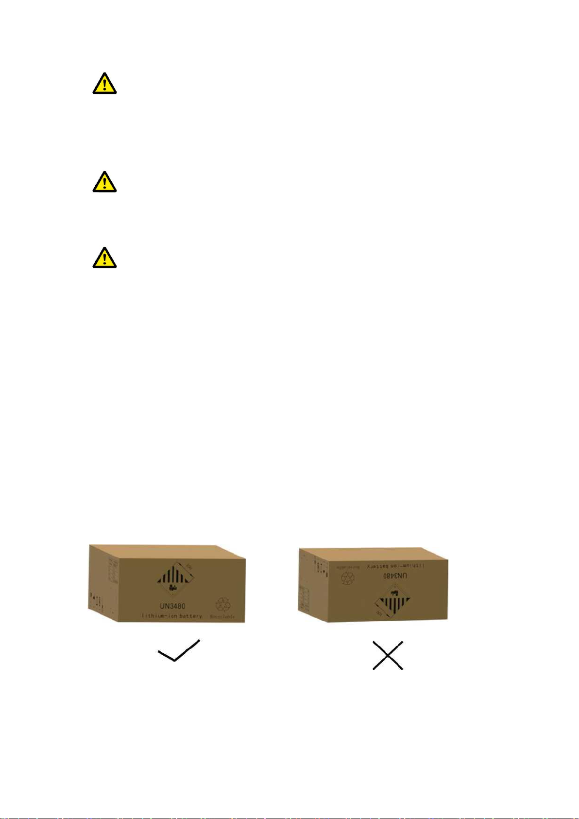
3.2 Permissible and Impermissible Storage Positions of a Packaged
Battery Module
The battery module can only be transported in an upright position. Please note that the battery
rack may be very top-heavy.
12
4. Preparation
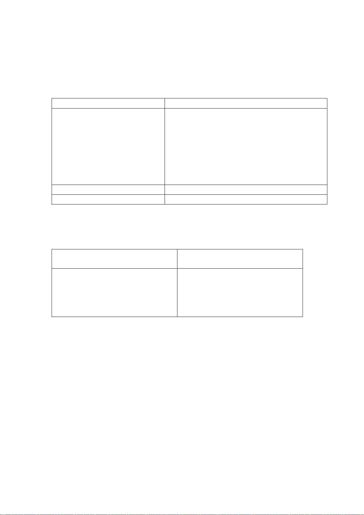
4.1 Tools required
TOOL
USE
Hexagonal wrench
• Install and connect the side beam/cross beam.
• Fix the L-shaped bracket to the side beam.
• Fix the base assembly to the side beam.
• Fix the diagonal brace to the beams on both sides.
• Fix the base to the side or cross beam.
• Install the ground wire.
• Fix the battery module and the high-voltage control box
on the rack.
10mm hexagon socket
• Fix the expansion screw
24mm wrench
• Adjust the height of the base and tighten the nut.
4.2 Auxiliary Tools and Materials Required
AID/MATERIAL
Auxiliary tools/materials
USE
Fastening materials (M4*12 M6*12 screws,
M6*100 expansion screws, M6 nuts)
1. Assemble the battery racks and fix them
on the wall or connect the two racks.
2. Assemble the battery modules and
high-voltage control boxes, and fix them to
the racks.
13
5. Description and installation of BOS-GL battery
5.1 Installation Precautions
WARNING! Possible damage to the building due to static overload
1. The total weight of the battery storage system is 596kg. Ensure that the installation site has
sufficient bearing capacity.
2. When selecting the installation site, consider the transportation route and necessary site
cleanup.
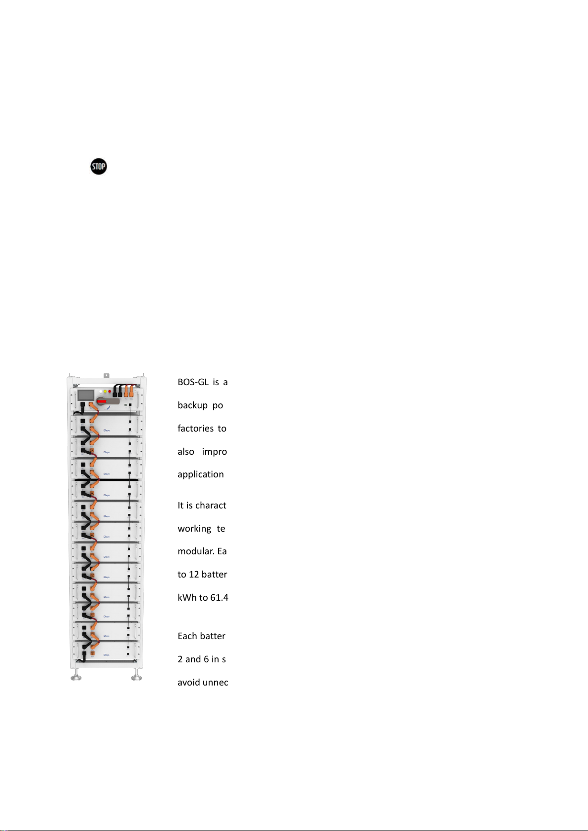
5.2 BOS-GL Product Description
BOS-GL is a high-voltage lithium-ion battery system. It provides a reliable
backup power supply for supermarkets, banks, schools, farms and small
factories to smooth the load curve and achieve peak load transfer. It can
also improve the stability of renewable systems and promote the
application of renewable energy.
It is characterized by high integration, good reliability, long service life, wide
working temperature range, etc. The battery energy storage system is
modular. Each battery module has a capacity of 5.12 kWh. It can support up
to 12 battery modules in series. Its total energy can be expanded from 15.36
kWh to 61.44 kWh.
Each battery pack and PDU has four connectors. When 12 battery packs are
2 and 6 in series, if other connectors are no longer used, use a dust cover to
avoid unnecessary damage to the connectors.

14
5.3 Technical Data
The energy of the battery system
(3~12 battery modules)
3battery modules
15.36kWh
4battery modules
20.48kWh
5battery modules
25.6kWh
6battery modules
30.72kWh
7battery modules
35.84kWh
8battery modules
40.96kWh
9battery modules
46.08kWh
10battery modules
51.2kWh
11battery modules
56.32kWh
12battery modules
61.44kWh
Charge-discharge rate (Max)
1C
Battery cell chemistry
LiFePO4
Maximum charging/discharging current
100A
Module capacity
100Ah
Working voltage
538~691V
Working temperature
Charge: 0~55℃/Discharge:-20~55℃
Humidity
5% - 85% (RH)
The altitude of the installation site
≤ 2000 m
Dimensions (W x D x H)
13th floor: 530x602x2187 mm
Warranty period
10 years
The total weight (12 battery modules, 1 rack)
596 kg
Weight of each battery module/battery rack
44 kg | 51 kg(3U-HRack 2G)
Case protection grade
IP20
Certification
FFC/UL1973/ UN38.3

15
5.4 Description of Rack
5.4.1 3U-HRack 2G Parts description
No.
Description
①
Side beam
②
Top beam
③
Bottom beam
④
Left diagonal brace
⑤
Right diagonal brace
⑥
Round head hexagon socket combination screws
⑦
Hexagonal wrench
⑧
Base
⑨
Rack fastener
⑩
Left base plate unit
⑪
Right base plate unit
⑫
Paint-breaking pad

16
5.4.2 Installation of Rack
①Take out two side beams and top and bottom beams and assemble them into a rectangular
frame, connect the two top beams with the side beams, and then fix the side beams and top
beams with the round head hexagon combination screws and hexagonal wrench. After fixing,
take two bottom beams and connect the side beams, and fix the side beams and bottom beams
with the round head hexagon socket combination screws and hexagonal wrench.
②The left and right diagonal braces are fixed on both sides of the beam with round head
hexagon combination screws and hexagon wrenches.
③Fix the two left base plate units to the lower left and upper right corners of the lower rack
using the round head hexagon socket combination screws and hexagonal wrench. Similarly, fix
the two right base plate units to the upper left and lower right corners of the lower rack using the
roundhead hexagon combination screws and the hexagonal wrench.
④Screw the base into the bottom plate and secure it with hexagonal wrench or by hand.
⑤ When installation is complete, stand the rack up.
⑥To fix the rack on the wall, use a hexagonal wrench to install the rack fastener on the socket
combination screw hole above the rack and fix it with the socket combination screw. Fix the
other side of the rack with the wall using round head hexagon combination screws. To fix two
racks together, install the rack fasteners on the hexagon socket combination screw holes above
the frame, and fix them together with hexagon socket combination screws and nuts.

17

18

19
This manual suits for next models
9
Table of contents
Other Deye Storage manuals


Popular Storage manuals by other brands


Seagate
Seagate ST3660A - Medalist 545 MB Hard Drive product manual

Cisco
Cisco UCS Invicta C3124SA manual

Seagate
Seagate ST9500420AS - Momentus 7200.4 500 GB Hard... datasheet

Integral
Integral P2NSX user manual

Maxtor
Maxtor Personal Storage 5000LE Specifications

Seagate
Seagate FreeAgent Desktop 1TB quick start guide

Fujitsu
Fujitsu ETERNUS DX60 S3 user guide

Buffalo
Buffalo WS-QV4TL/R5 Replacement manual

ATTO Technology
ATTO Technology FastStream SC 5700 Specifications

HP
HP J3278B - SureStore CD-ROM Server/Tower 7 NAS... Administrator's guide

Sun Microsystems
Sun Microsystems StorageTek SL500 Local Operator Panel Guide

Clickfree
Clickfree Traveler quick start guide