DEZEGA HIHPG2 User manual
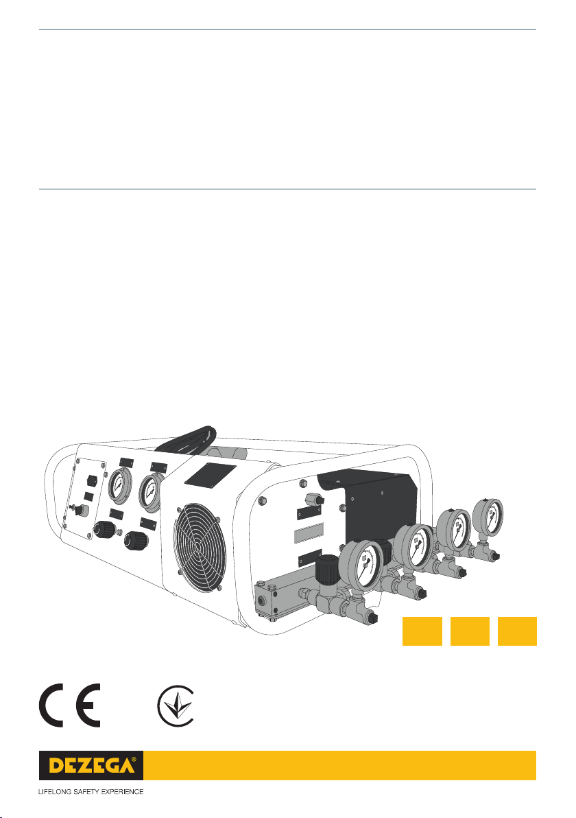
OXYGEN GAS
BOOSTER SYSTEM
OKSİJEN GAZI DOLUM POMPASI SİSTEMİ
КОМПРЕСОР КИСНЕВИЙ ДОТИСКАЮЧИЙ
HIHPG2
User manual
Kullanım Kılavuzu
Керівництво з експлуатації
TREN
Red. 22.12.2022_V1
2006/42/EC
2014/30/EU
2014/35/EU
ТР 62 від 30.01.2013
ТР 1067 від 16.12.2015
ТР 1077 від 16.12.2015
UK

COMPLIES WITH:
THE REQUIREMENTS OF THE FOLLOWING REGULATIONS OF THE
EUROPEAN UNION
DIRECTIVE 2006/42/EC, DIRECTIVE 2014/30/EU, DIRECTIVE
2014/35/EU.
AVRUPA BİRLİĞİ’NİN AŞAĞIDAKİ YÖNETMELİK
KURALLARINA UYGUNDUR:
2006/42/EC SAYILI AVRUPA BIRLIĞI DIREKTIFI, 2014/30/EU SAYILI
DIREKTIF, 2014/35/EU SAYILI DIREKTIF.
ВІДПОВІДАЄ:
ВИМОГАМ НАСТУПНИХ НОРМАТИВНИХ АКТІВ:
ТЕХНІЧНИЙ РЕГЛАМЕНТ БЕЗПЕКИ МАШИН, ЗАТВЕРДЖЕНИЙ
ПОСТАНОВОЮ КМУ ВІД 30.01.2013 р. № 62;
ТЕХНІЧНИЙ РЕГЛАМЕНТ НИЗЬКОВОЛЬТНОГО ЕЛЕКТРИЧНОГО
ОБЛАДНАННЯ, ЗАТВЕРДЖЕНИЙ ПОСТАНОВОЮ КМУ
ВІД 16.12.2015 р. № 1067; ТЕХНІЧНИЙ РЕГЛАМЕНТ
З ЕЛЕКТРОМАГНІТНОЇ СУМІСНОСТІ ОБЛАДНАННЯ,
ЗАТВЕРДЖЕНИЙ ПОСТАНОВОЮ КМУ ВІД 16.12.2015 р. № 1077.
Evidenced by a declaration of conformity 6E1.42/30/35/2.000.
6E1.42/30/35/2.000 uygunluk beyanı ile kanıtlanmıştır.
Підтверджено декларацією про відповідність
6U1.62/1067/1077/2.000.
USER MANUAL........................................................................................ 3
KULLANIM KILAVUZU ........................................................................... 17
КЕРІВНИЦТВО З ЕКСПЛУАТАЦІЇ ......................................................... 31
TR
UK
EN

OXYGEN GAS
BOOSTER SYSTEM
HIHPG2
USER
manual
EN

TABLE OF CONTENTS
Introduction................................................................................................ 5
1. Overall Description.............................................................................. 6
1.1. Gas Supply System ...................................................................... 6
1.2. Gas Output System ...................................................................... 6
2. Safety.................................................................................................... 7
2.1. High Pressure Gas........................................................................ 7
2.2. Oxygen Gas................................................................................... 7
3. System Installation and Operation..................................................... 8
3.1. Installation .................................................................................... 8
3.2. Connections.................................................................................. 8
3.3 Operation ....................................................................................... 8
3.4. Removal of test vessel or similar................................................ 9
3.5. Removal of supply hose ............................................................ 10
4. Individual Components..................................................................... 10
4.1. Function....................................................................................... 10
4.2. Options may be supplied by the order.................................... 12
4.3. Periodic Maintenance ................................................................ 13
4.3.1. Basic System.................................................................... 13
4.3.2. Components ..................................................................... 14
4.4. Repairs and Recommended Seal Kits...................................... 14
5. Specifications .................................................................................... 14
6. Warranty ............................................................................................. 15
HIHPG2 (Directive 2006/42/EC) | (Directive 2014/30/EU) | (Directive 2014/35/EU) DEZEGA
5
INTRODUCTION
This User Manual (hereinafter referred to as «Manual») is intended to study the design and the rules
for use of gas Booster system HIHPG2 (hereinafter referred to as the «booster»). It also contains
instructions for the proper use of the booster.
The Manual describes the principles of installation and operation, overall description, rules for
preparation of the booster for work as well as a procedure for technical condition check and
recommendations for maintenance of the booster.
The Manual uses a series of symbols to draw the user’s attention to features, problems, and dangerous
situations as may be encountered in the course of the use and maintenance of the booster.
NOTE!
This symbol contains additional information about the rules, techniques and recommendations for the
proper use of the booster.
CAUTION!
This symbol indicates a dangerous situation that, if not avoided, could lead to equipment damage,
personal injury, or even death of the user or service personnel.
DANGEROUS!
This symbol indicates an unavoidable dangerous situation that, if no precautions are taken, could lead to
serious injury or death of the user.

HIHPG2 (Directive 2006/42/EC) | (Directive 2014/30/EU) | (Directive 2014/35/EU) DEZEGA
6
1. OVERALL DESCRIPTION – GAS BOOSTER SYSTEM HIHPG2.
The gas Booster system is designed to increase gas pressure from a cascade storage system from as
low as 2 MPa (300-psi) up to 27,5 MPa (4000-psi) to allow filling cylinders or test vessel. The unit is
a two-man portable system housed within an aluminum tubular frame. The frame supports a control
panel with valves and gauges panel mounted.
The system is designed for in-plant operation.
1.1. Gas Supply System
The unit is designed to boost gas from as low as 2 MPa (300-psi) up to 27,5 MPa (4000-psi).
The supply source may be from a cascade storage system. When the supply pressure drops
below 2 MPa (300-psi), the booster will automatically turn o using the inlet pressure switch and
restart approximately at 2,4 MPa (350-psi).
The unit is equipped with one (1) inlet port.
NOTE!
The gas supply must not exceed 27,5 MPa (4000-psi).
1.2. Gas Output System
The unit is designed to provide a high pressure gas output up to 27,5 MPa (4000-psi) with the output
safety relief valve set at 28,6 MPa (4150-psi). This high pressure gas output will be maintained at 27,5
MPa (4000-psi) and the booster will automatically turned o using the outlet pressure limit switch and
restart when the outlet pressure drops approximately to 20,7 MPa (3000-psi).
The unit is equipped with one (1) outlet port and one (1) vent port. All vents from the gas chambers,
relief valve and vent valve are connected to this port. Optionally may be supplied with outlet 4-port
manifold.
If the selected fill pressure is less than the gas supply pressure, no boosting is needed; the supply
gas will free flow across the booster by opening the inlet & outlet gas valves.
If the selected fill pressure is the same or higher than the gas supply pressure, the booster should be
turned on by pressing the starter switch on the panel or remotely using the on/o switch. It will then
cycle and automatically maintain approximately 4000-psi upstream of relief.
NOTE!
The system pressure gauge will always show the pressure upstream of the relief valve with or without
the boosters operating.
NOTE!
This unit must be located in a clean, well-ventilated area and operated only by authorized personnel.
HIHPG2 (Directive 2006/42/EC) | (Directive 2014/30/EU) | (Directive 2014/35/EU) DEZEGA
7
2. SAFETY
2.1. High Pressure Gas:
Оpen all valves slowly. Crack all fittings slowly. Monitor all pressure gauges so that lines or fittings
are vented before any disassembly.
CAUTION!
Gas at high pressure in even a small volume contains substantial stored energy. Therefore, if suddenly
released it is potentially dangerous:
• Piping or fitting failure can cause a tube or hose to whip with severe force.
• Quickly opening a vent valve can damage hearing and penetrate exposed skin.
• Quickly opening a line valve can cause a momentary hot spot down stream.
2.2. Oxygen Gas
CAUTION!
Do not use an oxygen booster for any other gas without a permission from the manufacturer even
occasionally. Although other gases may be perfectly pure, we have found that operating personnel tend
to be more careless with connecting hoses and fittings used with other gases, creating a potential for
contaminating the booster.
2.2.1. Service of the oxygen containing sections of the booster (or accessories) involves a more
stringent procedure to insure cleanliness. We prefer that the booster be returned to the supplier
for service.
2.2.2. The oxygen to be boosted must be free of oil or other hydrocarbons at its source.
2.2.3. Maximum compression ratios (maximum outlet pressure psia, divided by minimum inlet
pressure psia). The maximums shown in the table below must be observed at all times to avoid
excessive heat:
Oxygen inlet < 2 MPa (300-psi) Oxygen inlet > 2 MPa (300-psi)
Single Stage: 6:1 8:1
NOTE!
For heavy duty, continuously operating applications, we recommend that the above compression
ratios be reduced even further, where feasible, with additional staging.
CAUTION!
DO NOT exceed 27,5 MPa (4000-psi) output.
DO NOT exceed 1,4 MPa/min (200 psi/min) transfer rate for pure Oxygen and
0,3-0,5 MPa (50-70 psi/min) during mixing
DO NOT use ball valves. Use slow-opening globe or needle valves that contain seats made from
oxygen-compatible polymers.
NOTE!
Eye protection during operational or maintenance procedures is recommended.
HIHPG2 (Directive 2006/42/EC) | (Directive 2014/30/EU) | (Directive 2014/35/EU) DEZEGA
8
3. SYSTEM INSTALLATION AND OPERATION
The Gas Booster system is designed to be portable or stationary. After the power cord, gas supply,
and gas output connections are made, no further securing in place of the unit should be necessary.
CAUTION!
Before operation, make sure all tubing, hoses, piping, and connections are capable of the specified
maximum operating pressures of the system. Make sure all connections, pipe work, hoses, and other
parts that will come in contact with oxygen, have been thoroughly cleaned for oxygen service. Make
sure all openings at cylinder hose connections and piping are cleaned and free of dust, oil, and grease.
Visual inspection and/or wipe test are recommended.
3.1. Installation
3.1.1. Install the Gas Booster System within 0,9-1,2 m (3-4 feet) away from the cascade system
or high pressure compressor storage tank and the fill cylinder(s).
3.1.2. Ensure cascade storage system valve(s) are closed.
3.1.3. Allow 20-30 cm (8"-12") of space all around the gas booster system for proper ventilation.
3.2. Connections
3.2.1. Connect power cord to electrical source, 220-V, 1-Phase, 60/50-Hz.
3.2.2. Connect the inlet gas supply via a 2-meter long hose with G1/4 and G3/4 connectors
to the G1/4 inlet port of the gas booster system and to the G3/4 port of the cascade storage
system.
3.2.3. Connect outlet gas supply via 1 meter long hose with G1/4 F and G1/4 M (with adaptor
zccording to the cylinder connection) connectors to the G1/4 M otlet port of the gas booster
system and to the port of the cylinder.
NOTE!
Make all hose and/or tube connections to the gas booster system with all valves on cascade
system or high pressure compressor storage tank closed on the unit. Maintain absolute cleanliness
in handling and storing all connecting lines.
3.3. Operation
3.3.1. Make sure all connections have been properly made.
3.3.2. Make sure the cylinder or test vessel has been placed in an appropriate fill station.
3.3.3. Make sure the automatic outlet high pressure limit switch item 7 (PS-2) (Figure 1) does
not exceed the maximum pressure rating of the cylinder or test vessel.
CAUTION!
Pressure switch settings are factory pre-set and should not require any adjustment. Improper
adjustment of pressure switches could result in physical injury.
Please contact the manufacturer for adjustment instructions.
3.3.4. Make sure gauges item 5 (PG-1) and (PG-2) (Figure 2) show zero pressure.
3.3.5. Make sure valves item 8 (V-1) and (V-2) (Figure 2) are closed.
3.3.6. Slowly open the valve on a cascade storage system. Inlet pressure gauge item 5
(PG-1) and outlet pressure gauge item 5 (PG-2) should read the same gas pressure in the supply
storage system.

HIHPG2 (Directive 2006/42/EC) | (Directive 2014/30/EU) | (Directive 2014/35/EU) DEZEGA
9
3.3.7. Attached gas outlet hose assembly (customer provided) to cylinder or test vessel
assemblies.
CAUTION!
Do not refill any cylinder or test vessel assembly that is damaged. Failures to inspect, depressurize,
and remove damaged cylinder or test vessel assembly may result in serious injury or death to
personnel.
Prior to charging a cylinder or test vessel assembly, inspect for evidence of exposure to
chemicals, high temperature, impact damage, or worn components.
3.3.8. Slowly open the cylinder or test vessel valve to full open, then back o the valve ¼ turn.
3.3.9. Slowly open the outlet valve item 8 (V-1) on the gas booster system panel.
NOTE!
Outlet pressure gauge item 5 (PG-2) and inlet pressure gauge item 5 (PG-1) must equalize and read
the same pressure. Make sure the supply pressure is higher than the low pressure limit switch
item 6 (PS-1). If not, the booster system will not operate; replace the cascade cylinder.
3.3.10. Turn the gas booster system on with the starter switch on the booster system panel.
NOTE!
When charging to a specific pressure and stopping, the pressure will normally fall back somewhat
as the gas cools.
3.3.11. Monitor filling pressure by reading pressure on the outlet gauge item 5 (PG-2).
3.3.11.1. The gas booster system may be manually shut o, for any reason, at any
time, before it reaches the pre-set pressure of the automatic high pressure limit switch
item 7 (PS-2).
3.3.11.2. If the gas booster system has not been shut o manually, it will shut o at the
preset pressure of the automatic high pressure limit switch item 7 (PS-2).
3.3.11.3. If the high pressure limit switch item 7 (PS-2) should malfunction or has been
tampered with, the safety relief valve item 3 (RV-1) (Figure 1) in the gas booster system
will automatically relieve the pressure.
CAUTION!
Before opening vent valve item 8 (V-2), ensure all personnel stand clear to avoid serious
injury or death from flying debris. Operator must wear protective eyewear and hearing
protection to prevent personnel injury.
3.4. Removal of the cylinder or test vessel
3.4.1. Close the cylinder or test vessel fully and close outlet valve item 8 (V-1) on the gas
booster system panel; slowly open vent valve item 8 (V-2) on the gas booster system panel to
vent gas between each cylinder or test vessel assembly and the gas booster system.
3.4.2. Disconnect outlet hose assembly from the cylinder or test vessel assembly.
NOTE!
Before charging the next cylinder or test vessel, close vent valve item 8 (V-2) on the gas booster
system panel. Repeat steps 3.3.8 through 3.3.11.

HIHPG2 (Directive 2006/42/EC) | (Directive 2014/30/EU) | (Directive 2014/35/EU) DEZEGA
10
3.5. Removal of the cylinder or test vessel
3.5.1. Close cascade storage system valve(s).
CAUTION!
Before opening vent valve item 8 (V-2), ensure all personnel stand clear to avoid serious injury or
death from flying debris. Operator must wear protective eyewear and hearing protection to prevent
personnel injury.
3.5.1. Slowly open vent valve item 8 (V-2) on the gas booster system panel, and outlet shuto
valve item 8 (V-1) to vent the high pressure gas circuit.
CAUTION!
All gauges item 5 (PG-1) and (PG-2) must read zero pressure.
4. INDIVIDUAL COMPONENTS
4.1. Functions
Item 13
Item 6
Item 7
Item 3
Item 2Item 1 Crankshaft mechanism
Item 9,10
Item 4
Figure 1. View from above
Item 1: Electric Motor: A device that uses electrical energy to produce mechanical
energy. The mechanical energy is transferred through a shaft to the speed reducer and
crankshaft mechanism to generate the reciprocating action.

HIHPG2 (Directive 2006/42/EC) | (Directive 2014/30/EU) | (Directive 2014/35/EU) DEZEGA
11
Item 2: Speed Reducer: Provides constant rotating speed in cycles/min to the crankshaft.
Set at 88 cycles/min (CPM).
Item 3: Safety Relief Valve (RV-1): Prevent cylinders from being over pressured. Factory
set at 28,6 MPa (4150-psi).
Item 4 Gas Booster ratio 30:1: Double acting, single stage chambers, ratio 30:1.
Item 2
Item 1
Item 12
Item 4
Hour-meter
Input Power cable
Crankshaft mechanism
Item 3
Item 5
Item 8
Item 11
Electrical panel
Outlet 4-port manifold
Gas intel port
Item 13
Item 9,10
Created in Free Online PDF to DWG Converter by CADSoftTools
http://www.cadsofttools.com/pdf-to-dwg-online/
Item 2
Item 1
Item 12
Item 4
Hour-meter
Input Power cable
Crankshaft mechanism
Item 3
Item 5
Item 8
Item 11
Electrical panel
Outlet 4-port manifold
Gas intel port
Item 13
Item 9,10
Created in Free Online PDF to DWG Converter by CADSoftTools
http://www.cadsofttools.com/pdf-to-dwg-online/
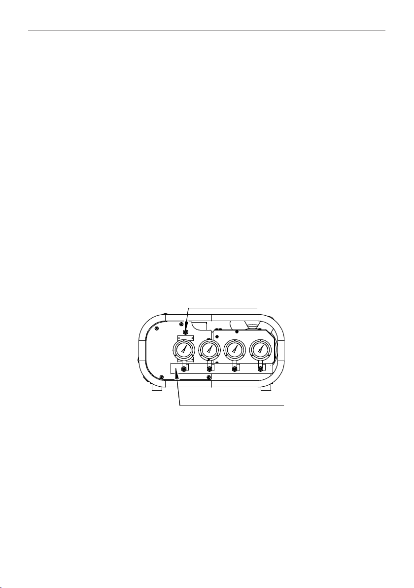
Figure 2. Front view
Item 5: Inlet Pressure Gauge (PG-1): Indicates the inlet pressure from the cascade
storage system, 0-34,5 MPa (0-5000 PSI).
Item 5: Outlet Pressure Gauge (PG-2): Indicates charging air pressure, 0-34,5 MPa
(0-5000 PSI).
Item 6: Low Pressure Limit Switch: Normally open. It senses inlet pressure from the
cascade storage system and stops the system when the pressure drops below the set
point and automatically restarts when the pressure exceeds 2,4 MPa (350-psi). Factory
set at 2 MPa (300-psi).
Item 7: High Pressure Limit Switch (PS-2): Normally closed. It senses outlet pressure
from the high pressure boost system and stops the system when the pressure exceeds
the set point and automatically restarts when the pressure drops approximately
to 20 MPa (3000-psi). Factory set at 27,5 MPa (4000-psi).
Item 8: Outlet shuto valve (V-1): Needle type controls the gas flow through the high
pressure boost system to the fill cylinder, manually operated.
Item 8: Outlet Vent valve (V-2): Needle type used to release gas pressure from the high
pressure gas boost system and fill the cylinder.
Item 9: Gas Inlet Filter (F-1): Remove particles down to a nominal 5-10 microns that
may migrate from the cascade cylinders or high pressure compressor storage tank.
Note: This filter will not intercept liquid contaminates.
Item 10: Gas Outlet Filters (F-2): Remove particles down to a nominal 5-10 microns
from the high pressure boost system discharge prior to entering the fill hose assembly
(hose assembly not provided).
HIHPG2 (Directive 2006/42/EC) | (Directive 2014/30/EU) | (Directive 2014/35/EU) DEZEGA
12
Item 11: Tubular Frame: Tubular frame with control panels and shock absorbers.
Item 12: Cooling fan: Provides cooling to the high pressure boost system at a rate of
5 m3/min (176-cfm).
Item 13: Outlet Manifold: Stainless Steel block, supports outlet pressure gauge item 5
(PG-2), outlet pressure relief valve item 3 (RV-1), high pressure limit switch item 7 (PS-2),
outlet shuto valve item 8 (V-1) and vent valve item 8 (V-2). Pressure rated to 41,5 MPa
(6000 PSI).
Shock Absorbers: Used to eliminate vibration from the motor and compression
mechanism are operating.
Hour-meter: 6-digit analog meter used to record the operating time in hours, resettable.
Crankshaft Mechanism: Cam type that provides the reciprocating action required to
boost gas pressure assuring smooth running operation.
Input Power cable: 6-foot in length. Power plug not included.
Electrical Enclosure: Houses the electrical wiring control system
Control panel: Includes gas outlet valve item 8 (V-1), vent valve item 8 (V-2), inlet pressure
gauge item 5 (PG-1), and outlet pressure gauge item 5 (PG-2).
Electrical panel: Includes start/stop control button, circuit breaker reset button, and
hourmeter.
Item 2
Item 1
Item 12
Item 4
Hour-meter
Input Power cable
Crankshaft mechanism
Item 3
Item 5
Item 8
Item 11
Electrical panel
Outlet 4-port manifold
Gas intel port
Item 13
Item 9,10
Created in Free Online PDF to DWG Converter by CADSoftTools
http://www.cadsofttools.com/pdf-to-dwg-online/
Item 2
Item 1
Item 12
Item 4
Hour-meter
Input Power cable
Crankshaft mechanism
Item 3
Item 5
Item 8
Item 11
Electrical panel
Outlet 4-port manifold
Gas intel port
Item 13
Item 9,10
Created in Free Online PDF to DWG Converter by CADSoftTools
http://www.cadsofttools.com/pdf-to-dwg-online/
Figure. 3. Side view
4.2. Options supplied by the order
Inlet hose assembly: 2-meter long with G3/4 connector on one end.
Low Pressure Limit Digital Switch: Normally open. Check inlet pressure from the
cascade storage system and stops the system when the pressure drops below the set
point and automatically restarts when the pressure exceeds 2,4 MPa (350-psi). Factory
set at 2 MPa (300-psi) - adjustable.
High Pressure Limit Digital Switch: Normally closed. Check outlet pressure from the
high pressure boost system and stops the system when the pressure exceeds the set
point and automatically restarts when the pressure drops approximately to 20 MPa
(3000-psi). Factory set at 27,5 MPa (4000-psi) – adjustable.

HIHPG2 (Directive 2006/42/EC) | (Directive 2014/30/EU) | (Directive 2014/35/EU) DEZEGA
13
Bleed valve (needle type): Outlet high pressure regulator 0-34,5 MPa (0-5000 PSI).
Outlet 4-port manifold: Stainless Steel block, with middle ports plugged with independent
gauges, shuto valves, vent valves, and two G1/4 outlet ports. Pressure rated to 40 MPa
(6000 PSI).
Outlet hose assembly: 1-meter with G1/4 connector on one end.
Adapter G1/4-G1/2 special: for filling the cylinder from P-30EX.
Adapter G1/4-M22x1.5: for filling the cylinder from P-70.
Vent channel: an option that allows you to fix the oxygen leak in one place.
Remote control panel: an optional solution for starting the compressor from another
room in case of such a request from the customer.
4.3. Periodic Maintenance
4.3.1. Basic System
All components are protected by 5-10 micron particle filters. If clean, dry supply gas, can be
assured, particle accumulation in these filters to the point of measurable pressure drop will
require extensive long term daily use. Element replacement annually may be justified. This is to
be more precisely determined upon inspection every 12 months after startup.
The oxygen boosters system comprises a number of dierent components which are exposed
to high pressure oxygen. Depending on the frequency of usage, condition of the oxygen supply,
cycle rate, pressures, or any other conditions that may be detrimental to seal life. The following
is a SUGGESTED scheduled maintenance index.
NOTE!
Full precaution should be taken with regards to the cleanliness of the oxygen system.
• Moderate to Heavy Usage (for light usage, double intervals).
Performance Interval Maintenance Action
Before/after each use 1. Perform an overall visual check of the system.
2. Clean oxygen cylinder connections
Every 3-6 months
1. Check high pressure boost system for oxygen
leaking from vents, external leakage, and
overall performance.
2. Check tie rod bolts, relief valve and pressure
switch lock nuts for loosening.
Every 6-months 1. Test all pressure gauges
2. Inspect and clean/replace oxygen filters
Every 12-months 1. Inspect piping at full system pressure
2. Test the relief valve
Every 500 hours of use (Severe usage)
Every 2,000 hours of use (Normal usage) 1. Reseal high pressure boost system
It is importance to maintain the highest level of cleanliness of the tools and work bench. When
any assembly is dismantled, it is recommended they be cleaned with a residue free, approved
oxygen compatible agent to make sure they are oil, grease and dust free.
HIHPG2 (Directive 2006/42/EC) | (Directive 2014/30/EU) | (Directive 2014/35/EU) DEZEGA
14
It is well known that ordinary oils and greases contain hydrocarbons which can react violently
in the presence of oxygen. Any other foreign material permitted to enter the booster circuit
may also ignite spontaneously in high oxygen concentrations. Cotton particles and «flu» from
cleaning rags should be prevented from remaining on components prior to reassembly. A blow
gun with clean oil free nitrogen is recommended to help prevent particles from remaining on/in
components during reassembly.
4.3.2. Components
No periodic maintenance is recommended for any other components in the system. Therefore,
all tubing in the gas system can be left undisturbed removing the risk of contamination from
careless handling.
4.4. Repairs and Recommended Seal Kits
No components except high pressure gas sections should require repair or seal replacement over the
life of the HIHPG2 system unless damaged by accident or contaminated gas. In such instances, refer
to individual item part no. drawings for instruction.
Part No. Ref. Dwgs Description Qty
Model HIHPG2 - seal kit
SK2G-30V-O 132308-111-O Gas section, ratio 30:1 2
In general, periodic seal replacement without symptoms indicating excessive wear or leakage is not
recommended.
CAUTION!
If disassembly and repair is indicated for any component in the gas stream including tubing, fittings,
hoses or booster pumping sections, check valves or interstage tubing the user should contact with
supplier, for current recommended cleaning compounds and procedures for oxygen level cleanliness.
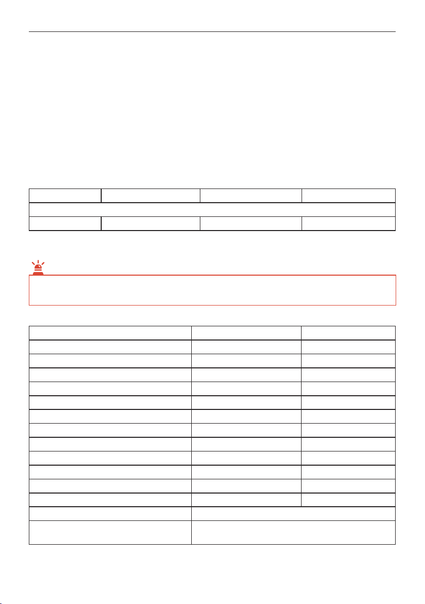
5. SPECIFICATIONS
Motor rating 2HP
Current @ 220 Volts, 1-phase 10.2 Amps
Operating Speed, Cycles per minute 88 CPM
Weight 66 (145) Kg (Pounds)
Noise level @ 3 ft 60 dB(A)
Inlet & outlet ports ¼" JIC Male**
Vent port ¼" NPTF**
Cooling Fan 5 (176) m3/min (CFM)
Delta temperature (gas outlet vs. ambient) 8 - 14 (15-25) °C (°F)
Operational ambient temperature range -40…+90 (-40 to +200) °C (°F)
Inlet pressure range 2-27,5 (300-4000) MPa (psi)
Operating pressure range 2-27,5 (300-4000) MPa (psi)
Overall dimensions (L x W x H) 812x558x279 mm
Cooling method Air-Cooled
Drive type
Stages
Direct Drive
1-stage, Double acting
• All data is with 5 % tolerance and is related to ambient conditions of 20 °C (68 °F) and
0,1 MPa (14,7 PSI).
** Adapters can be supplied on request

HIHPG2 (Directive 2006/42/EC) | (Directive 2014/30/EU) | (Directive 2014/35/EU) DEZEGA
15
6. WARRANTY
12-months from the date of purchase or 18-months from the date of production.
This warranty does not include o-rings, seals or failures caused by lack of proper maintenance,
incompatible fluids, and foreign contaminants in the drive section, in the pump section or application
of pressures beyond catalog ratings. Products believed to be originally defective may be returned,
freight prepaid, for repair and/or replacement to the distributor or to the manufacturer.
If the unit has been disassembled and reassembled without prior written authorization, the warranty
is void if it has been improperly reassembled or substitute parts have been used in place of factory
manufactured parts.
Any modification to any product you have made or may make in the future has been and will be
at your sole risk and responsibility, without approval or consent. Supplier disclaims any and all
liability obligation, or responsibility for the modified product. And for any claims, demands or causes
of action for damage or for personal injuries resulting from the modification and/or use of such a
modified product.
Supplier obligation with respect to its products shall be limited to replacement, and in no event
shall supplier be liable for any loss or damage, consequential or special, of whatever kind or
nature, or any other expense which may arise in connection with or as a result of such products
or the use or incorporation thereof in a job. This warranty is expressly made in lieu of all other
warranties of merchantability and fitness for a particular purpose. No express warranty and no
implied warranties whether of merchantability or fitness for a particular purpose or otherwise,
other than those expressly set forth above, shall apply to products.
Contact local representative in your country or call for DEZEGA
to get information about service center in your region
DEZEGA SP GUVENLIK URUNLERI SAN. VE TIC. A.S.
Legal address: Zafer Sb Mahallesi Nilufer Sok. No:30,
35410, Izmir / Geziemir
Phone/fax: +90(232)251-03-94, +90(232)252-03-94;
e-mail: turkey@dezega.com
Manufactured by:
HYDRAULICS INTERNATIONAL, INC.
9000 MASON AVE, CHATSWORTH, CA 91311


OKSİJEN GAZI DOLUM
POMPASI SİSTEMİ
HIHPG2
KULLANIM
kılavuzu
TR

İÇİNDEKİLER
Giriş........................................................................................................... 19
1. Genel açıklama .................................................................................. 20
1.1. Gaz Besleme Sistemi ................................................................. 20
1.2. Gaz Çıkış Sistemi........................................................................ 20
2. Güvenlik.............................................................................................. 21
2.1. Yüksek Basınçlı Gaz................................................................... 21
2.2. Oksijen Gazı................................................................................ 21
3. Sistem Kurulumu ve Çalışması ....................................................... 22
3.1. Kurulum....................................................................................... 22
3.2. Bağlantılar................................................................................... 22
3.3 Operasyon.................................................................................... 22
3.4. Test tankının veya benzerinin çıkarılması ................................ 23
3.5. Besleme hortumunun çıkarılması ............................................. 24
4. Tekli Bileşenler................................................................................... 24
4.1. İşlev.............................................................................................. 24
4.2. Seçenekler sipariș ile sağlanabilir ........................................ 26
4.3. Periyodik Bakım.......................................................................... 27
4.3.1. Temel Sistem .................................................................... 27
4.3.2. Bileşenler .......................................................................... 28
4.4. Onarımlar ve Tavsiye Edilen Sızdırmazlık Kitleri ..................... 28
5. Teknik Özellikler................................................................................. 28
6. Garanti................................................................................................ 29

HIHPG2 (2006/42/EC Sayılı dırektıf) | (2014/30/EU Sayılı dırektıf) | (2014/35/EU Sayılı dırektıf) DEZEGA
19
GİRİȘ
Bu Kullanım Kılavuzu (bundan böyle «Kılavuz» olarak anılacaktır), Gaz Dolum Pompası Sistem
HIHPG2ʼnin (bundan böyle «Dolum Pompası» olarak anılacaktır) tasarımını ve kullanım kurallarını
incelemeyi amaçlamaktadır. Ayrıca dolum pompasının doğru kullanımı için talimatlar içerir.
Kılavuz, kurulum ve çalıșma prensiplerini, genel tanımı, Dolum Pompasının ișe hazırlanması için
kuralların yanı sıra teknik durum kontrolü için prosedürü ve Dolum Pompasının bakımı için önerileri
açıklamaktadır.
Kılavuz, kullanıcının dikkatini Dolum Pompasının kullanımı ve bakımı sırasında karșılașılabilecek
özelliklere, sorunlara ve tehlikeli durumlara çekmek için bir dizi sembol kullanır.
NOT!
Bu sembol, Dolum Pompasının doğru kullanımı için kurallar, teknikler ve öneriler hakkında
ek bilgiler içerir.
DİKKAT!
Bu sembol, kaçınılmadığı takdirde ekipman hasarına, kișisel yaralanmaya ve hatta kullanıcının veya
hizmet personelinin ölümüne yol açabilecek tehlikeli bir durumu gösterir.
TEHLİKELİ!
Bu sembol, herhangi bir önlem alınmadığı takdirde kullanıcının ciddi șekilde yaralanmasına veya
ölümüne yol açabilecek kaçınılmaz tehlikeli bir durumu gösterir.

HIHPG2 (2006/42/EC Sayılı dırektıf) | (2014/30/EU Sayılı dırektıf) | (2014/35/EU Sayılı dırektıf) DEZEGA
20
1. GENEL AÇIKLAMA - GAZ DOLUM POMPASI
SISTEMİ HIHPG2.
Gaz Dolum Pompası Sistemi, tüplerin veya test tankının doldurulmasına izin vermek
için kaskad depolama sisteminden gelen gaz basıncını 2 MPa (300-psi) kadar düșük
bir seviyeden 27,5 MPa’a (4000-psi) çıkarmak için tasarlanmıștır. Ünite, alüminyum boru șeklindeki
bir șasi içinde yer alan, iki kișiyle tașınabilir bir sistemdir. Șasi, valfler ve gösterge paneli monte
edilmiș bir kontrol panelini destekler.
Sistem tesis içi çalıșma için tasarlanmıștır.
1.1. Gaz Besleme Sistemi
Ünite, gazı 2 MPa (300-psi) kadar düșük bir değerden 27,5 MPa’a (4000-psi) kadar çıkarmak için
tasarlanmıștır. Tedarik kaynağı kaskad depolama sisteminden olabilir. Besleme basıncı 2 MPa’ın
(300-psi) altına düștüğünde, basınç yükseltici giriș basınç șalterini kullanarak otomatik olarak kapanır
ve yaklașık 2,4 MPa’da (350-psi) yeniden bașlatılır.
Ünite bir (1) giriș portu ile donatılmıștır.
NOT!
Gaz beslemesi 27,5 MPa’ı (4000-psi) geçmemelidir.
1.2. Gaz Çıkıș Sistemi
Ünite, 28,6 MPa (4150-psi) olarak ayarlanmıș çıkıș emniyet tahliye valfiyle 27,5 MPa’a (4000-psi)
kadar yüksek basınçlı gaz çıkıșı sağlamak üzere tasarlanmıștır. Bu yüksek basınçlı gaz çıkıșı 27,5
MPa’da (4000-psi) tutulacak ve çıkıș basınç limiti șalteri kullanılarak Dolum Pompası otomatik olarak
kapanacak ve çıkıș basıncı yaklașık 20,7 MPa’a (3000-psi) düștüğünde yeniden bașlayacaktır.
Ünite bir (1) çıkıș portu ve bir (1) tahliye portu ile donatılmıștır. Gaz odalarındaki tüm tahliye delikleri,
tahliye vanası ve tahliye vanası bu porta bağlanır. İsteğe bağlı olarak çıkıș 4 portlu manifolt ile temin
edilebilir.
Seçilen dolum basıncı gaz besleme basıncından düșükse, Dolum Pompasına gerek yoktur; besleme
gazı, giriș ve çıkıș gaz valflerini açarak Dolum Pompası boyunca serbest akıșa girecektir.
Seçilen dolum basıncı gaz besleme basıncıyla aynı veya daha yüksekse, Dolum Pompası paneldeki
çalıștırma anahtarına basılarak veya açma/kapama düğmesi kullanılarak uzaktan açılmalıdır. Daha
sonra döngü yapacak ve otomatik olarak yaklașık 4000-psi tahliye akıșını koruyacaktır.
NOT!
Basınç tankı çalıșsın veya çalıșmasın, sistem basınç göstergesi her zaman tahliye vanasının yukarı akıș
basıncını gösterecektir.
NOT!
Bu ünite temiz, iyi havalandırılan bir alana yerleștirilmeli ve sadece yetkili personel tarafından
çalıștırılmalıdır.
This manual suits for next models
1
Table of contents
Languages:
Popular Air Compressor manuals by other brands

Ozito
Ozito 40L 2.5HP instruction manual

Scheppach
Scheppach GK520DCZ instruction manual

BLACKMER
BLACKMER NGH1013 Installation, operation and maintenance instructions

GreenWorks
GreenWorks 4104307 user manual

Ingersoll-Rand
Ingersoll-Rand P425AWIR Operating, Maintenance & Parts Manual

Draper
Draper 24973 instruction manual


