didimerge D17800 Series User manual
Copyright ©2007 Digimerge Technologies Inc.
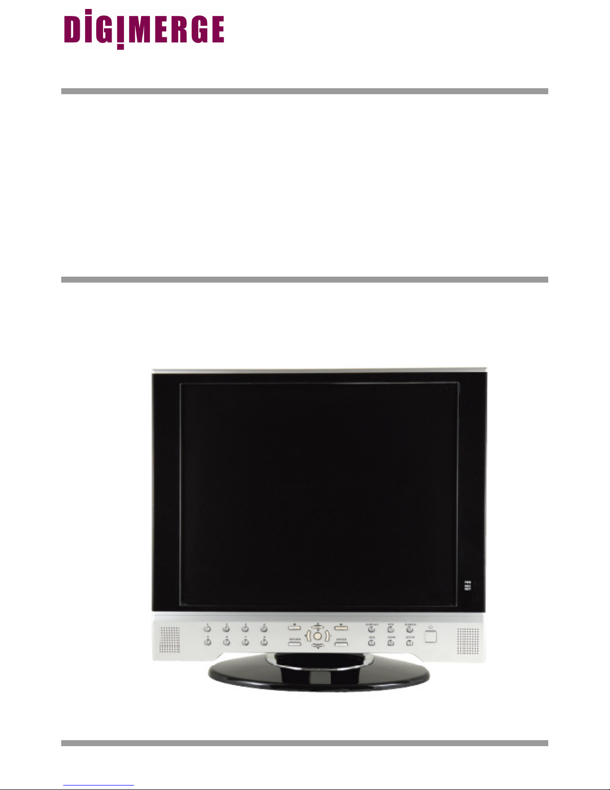
17” LCD MONITOR /
8 CHANNEL DVR COMBO
Instruction Manual
English Version 1.0
MODEL:
D17800 Series
Series Includes: D17800 Series (NTSC); D17800P Series (PAL)

ii
CAUTION
RISK OF ELECTRIC SHOCK
DO NOT OPEN
CAUTION: TO REDUCE THE RISK OF ELECTRIC SHOCK
DO NOT REMOVE COVER (OR BACK).
NO USER SERVICEABLE PARTS INSIDE.
REFER SERVICING TO A QUALIFIED SERVICE PERSONNEL
The lightning flash with arrowhead symbol, within an
equilateral triangle, is intended to alert the user to the
presence of uninsulated “dangerous voltage” within the
product’s enclosure that may be of sufficient magnitude
to constitute a risk of electric shock to persons.
The exclamation point within an equilateral triangle is
intended to alert the user to the presence of important
operating and maintenance (servicing) instructions in
the literature accompanying the appliance.
WARNING: TO PREVENT FIRE OR SHOCK HAZARD,
DO NOT EXPOSE THIS UNIT TO RAIN OR MOISTURE.
CAUTION: TO PREVENT ELECTRIC SHOCK, MATCH WIDE BLADE
OF PLUG TO WIDE SLOT, FULLY INSERT.
Thank you for purchasing the LCD / 8 Channel DVR Combo. Digimerge is committed to providing our
customers with a high quality, reliable security product.
This system offers a whole new level of security surveillance to the consumer market. Combining the
latest word in LCD displays, Digital Video Recording and CCTV Camera design, the system does more
than simply provide the sharpest video imaging (under any condition), large capacity video storage and
unparalleled ease of system control – it’s also made to provide the longest trouble free service with an
array of built-in diagnostics and commercial grade CCTV component design.
To learn more about the LCD / 8 Channel DVR Combo, and to learn about our complete range of
accessory products, please visit our website at:
http://www.Digimerge.com
Please visit us on the web for the most current Manuals, Quick Start
Guides and Firmware at:
http://www.Digimerge.com
iii
Important Safeguards
Important Safeguards
In addition to the careful attention devoted to quality standards in the manufacture process of your video
product, safety is a major factor in the design of every instrument. However, safety is your responsibility too.
This sheet lists important information that will help to assure your enjoyment and proper use of the video
product and accessory equipment. Please read them carefully before operating and using your video product.
Installation
1. Read and Follow Instructions - All the safety and
operating instructions should be read before the
video product is operated. Follow all operating
instructions.
2. Retain Instructions - The safety and operating
instructions should be retained for future reference.
3. Heed Warnings - Comply with all warnings on the
video product and in the operating instructions.
4. Polarization - Do not defeat the safety purpose of
the polarized or grounding-type plug.
A polarized plug has two blades with
one wider than the other.
A grounding type plug has two blades
and a third grounding prong.
The wide blade or the third prong are
provided for your safety.
If the provided plug does not fit into
your outlet, consult an electrician for
replacement of the obsolete outlet
5. .Power Sources - This video product should be
operated only from the type of power source
indicated on the marking label. If you are not sure of
the type of power supply to your location, consult
your video dealer or local power company. For video
products intended to operate from battery power, or
other sources, refer to the operating instructions.
6. Overloading - Do not overload wall outlets of
extension cords as this can result in the risk of fire
or electric shock. Overloaded AC outlets, extension
cords, frayed power cords, damaged or cracked wire
insulation, and broken plugs are dangerous. They
may result in a shock or fire hazard. Periodically
examine the cord, and if its appearance indicates
damage or deteriorated insulation, have it replaced
by your service technician.
7. Power-Cord Protection - Power supply cords should
be routed so that they are not likely to be walked on
or pinched by items placed upon or against them,
paying particular attention to cords at plugs,
convenience receptacles, and the point where they
exit from the video product.
8. Ventilation - Slots and openings in the case are
provided for ventilation to ensure reliable operation
of the video product and to protect it from
overheating. These openings must not be blocked
or covered. The openings should never be blocked
by placing the video equipment on a bed, sofa, rug,
or other similar surface. This video product should
never be placed near or over a radiator or heat
register. This video product should not be placed in
a built-in installation such as a bookcase or rack
unless proper ventilation is provided or the video
product manufacturer’s instructions have been
followed.
9. Attachments - Do not use attachments unless
recommended by the video product manufacturer as
they may cause a hazard.
10. Water and Moisture - Do not use this video product
near water. For example, near a bath tub, wash bowl,
kitchen sink or laundry tub, in a wet basement, near
a swimming pool and the like.
Caution: Maintain electrical safety. Powerline
operated equipment or accessories connected to
this unit should bear the UL listing mark of CSA
certification mark on the accessory itself and should
not be modified so as to defeat the safety features.
This will help avoid any potential hazard from
electrical shock or fire. If in doubt, contact qualified
service personnel.
11. Accessories - Do not place this video equipment
on an unstable cart, stand, tripod, or table. The video
equipment may fall, causing serious
damage to the video product. Use
this video product only with a cart,
stand, tripod, bracket, or table
recommended by the
manufacturer or sold with the video
product. Any mounting of the product
should follow the manufacturer’s
instructions and use a mounting accessory
recommended by the manufacturer.

iv
Important Safeguards
Service
13. Servicing - Do not attempt to service this video
equipment yourself as opening or removing covers
may expose you to dangerous voltage or other
hazards. Refer all servicing to qualified service
personnel.
14. Conditions Requiring Service - Unplug this video
product from the wall outlet and refer servicing to
qualified service personnel under the following
conditions.
A. When the power supply cord or plug is
damaged.
B. If liquid has been spilled or objects have fallen
into the video product.
C. If the video product has been exposed to rain
or water.
D. If the video product does not operate normally
by following the operating instructions. Adjust
only those controls that are covered by the
operating instructions. Improper adjustment of
other controls may result in damage and will often
require extensive work by a qualified technician
to restore the video product to its normal
operation.
E. If the video product has been dropped or the
cabinet has been damaged.
F. When the video product exhibits a distinct
change in performance. This indicates a need for
service.
15. Replacement Parts - When replacement parts are
required, have the service technician verify that the
replacements used have the same safety
characteristics as the original parts. Use of
replacements specified by the video product
manufacturer can prevent fire, electric shock or other
hazards.
16. Safety Check - Upon completion of any service or
repairs to this video product, ask the service
technician to perform safety checks recommended
by the manufacturer to determine that the video
product is in safe operating condition.
17. Wall or Ceiling Mounting - Any cameras provided
with this system should be mounted to a wall or
ceiling only as instructed in this guide, using the
provided mounting brackets.
18. Heat - The product should be situated away from
heat sources such as radiators, heat registers,
stoves, or other products (including amplifiers) that
produce heat.
Use
19. Cleaning - Unplug the video product from the wall
outlet before cleaning. Do not use liquid cleaners or
aerosol cleaners. Use a damp cloth for cleaning.
20. Product and Cart Combination - Video and cart
combination should be moved with care. Quick
stops, excessive force, and uneven surfaces may
cause the video product and car combination to
overturn.
21. Object and Liquid Entry - Never push objects for
any kind into this video product through openings as
they may touch dangerous voltage points or
“short-out” parts that could result in a fire or electric
shock. Never spill liquid of any kind on the video
product.
22. Lightning - For added protection for this video
product during a lightning storm, or when it is left
unattended and unused for long periods of time,
unplug it from the wall outlet and disconnect the
antenna or cable system. This will prevent damage
to the video product due to lightning and power line
surges.

v
General Precautions
FCC CLASS B NOTICE
Note:
This equipment has been tested and found to comply with the limits for a Class B digital device, pursuant to Part
15 of the FCC Rules. These limits are designed to provide reasonable protection against harmful interference in
a residential installation. This equipment generates, uses, and can radiate radio frequency energy and, if not in-
stalled and used in accordance with the instruction, may cause harmful interference to radio communications.
However, there is no guarantee that interference will not occur in a particular installation. If this equipment does
cause harmful interference to radio or television reception (which can be determined by turning the equipment on
and off), the user is encouraged to try to correct the interference by one or more of the following measures:
zReorient or relocate the receiving antenna
zIncrease the separation between the equipment and receiver
zConnect the equipment into an outlet on a circuit different from that to which the receiver is
connected
zConsult the dealer or an experienced radio or television technician for assistance
DIGIMERGE TECHNOLOGY INC.
http://www.Digimerge.com
NOTE
This equipment has been certified and found to comply with the limits regulated by FCC, EMC, and LVD. Therefore, it
is designated to provide reasonable protection against interference and will not cause interference with other appliance
usage.
However, it is imperative that the user follows this manuals guidelines to avoid improper usage which may result in
damage to the unit, electrical shock and fire hazard injury
In order to improve the feature functions and quality of this product, the specifications are subject to change without
notice from time to time.
General Precautions
1. All warnings and instructions of this manual should be followed
2. Remove the plug from the outlet before cleaning. Do not use liquid aerosol detergents. Use a water dampened cloth
for cleaning
3. Do not use this unit in humid or wet places
4. Keep enough space around the unit for ventilation. Slots and openings in the storage cabinet should not be blocked
5. During lightning storms, or when the unit is not used for a long time, disconnect the power supply, antenna, and cables
to protect the unit from electrical surge

vi
LCD/DVR COMBO FEATURES
LCD/DVR COMBO FEATURES
• Professional A-Grade LCD with ultra fast 8ms refresh rate and wide viewing angle (+/- 75
degrees vertical and horizontal)
• Pentaplex operation - simultaneously functionality:
zLive Viewing
zRecording
zPlayback
zBackup
zNetwork Controls
• MPEG4 Compression: Small File sizes without comprised video quality
• Installed Seagate SV35 Series HDD: Hard Drives specifically designed for optimal
performance in the commercial video security market. The series enables storage of a large
amount of digital video data, while providing fast access and review of recorded video. The
drives are designed to operate 24/7 for a minimum of 50,000 hours.
• S.M.A.R.T HDD Support (Self-Monitoring Analysis and Reporting Technology): Auto Detection
/ Recovery to ensure the HDD is functioning properly, ultimately prevents losing video data
• Browser Based Remote Client: View and control your DVR from any internet connected PC
with Internet Explorer (does not require Digimerge Client software).
• Universal Camera Inputs: Supports proprietary 6 PIN DIN or any professional grade camera
• Spot Video Out: Allows the user to connect another monitor to the system and display selected
video channels in another location.
• Independent Channel Control: Customize the recording parameters to the surveillance
application for each camera on the system. For Example:
zCam 1 is pointing at a Cash Register - The System allows you to set the parameters for real
time recording at high resolution so all data is captured in Real Time.
zCam 2 is recording the Front Door - The System allows you to set the parameters to record at a
lower frame rate and at a lower resolution to save Hard Drive space.
• Covert Camera function: The camera is not viewable on the monitor, but the video will still be
recorded
• Pre-Event Recording: The system will automatically record a preset amount of time before
motion triggers the recording (this feature allows the user to see what events occurred leading
up to the event)

7
Table of Contents
Table of Contents
Getting Started .......................................................................................... 9
Front Panel ...................................................................................... 10 - 13
Rear Panel ....................................................................................... 14 - 15
Remote Control ....................................................................................... 16
Display Modes .................................................................................. 17 -19
PTZ (Pan/Tilt/Zoom) & Focus Controls ................................................... 20
System Power Off ................................................................................... 21
Search Mode .................................................................................... 22 - 23
Menu Navigation Controls & Tips ........................................................... 24
System Setup Controls ........................................................................... 25
Display Menu ................................................................................... 26 - 30
OSD (Onscreen Display) ........................................................................................................... 26
MONITOR .................................................................................................................................. 27
SEQUENCE .............................................................................................................................. 28
SEQUENCE SETUP MODE ...................................................................................................... 29
SPOT-OUT ................................................................................................................................ 30
SCREENSAVER ....................................................................................................................... 30
Camera Menu .................................................................................. 31 - 33
CAMERA TITLE ........................................................................................................................ 31
COLOR SETUP ......................................................................................................................... 32
PTZ SETUP ............................................................................................................................... 32
PTZ PROPERTIES .................................................................................................................... 33
MOTION SENSOR .................................................................................................................... 33
Sound Menu ............................................................................................ 34
SOUND ...................................................................................................................................... 34
BUZZER .................................................................................................................................... 34
System Menu ................................................................................... 35 - 41
DATE/TIME ............................................................................................................................... 35
NETWORK ................................................................................................................................ 36
NETWORK ................................................................................................................................ 37
MAIL SETUP ............................................................................................................................. 37
USER MANAGEMENT .............................................................................................................. 38
SYSTEM MANAGEMENT .................................................................................................. 39 - 41
CONTROL DEVICE ................................................................................................................... 41
Event / Sensor ................................................................................. 42 - 45
HDD EVENT .............................................................................................................................. 42
ALARM INPUT .......................................................................................................................... 43
ALARM OUT 43 - 44
BUZZER OUT ............................................................................................................................ 44
EMAIL NOTIFICATION .............................................................................................................45
Disk Management ................................................................................... 46

8
Table of Contents
Recording Menu Controls ................................................................ 47 - 48
Recording Menu Options ........................................................................................................... 47
Recording Operations ................................................................................................................ 48
Switching Between Simple and Advanced Modes .................................................................... 48
Simple Recording Mode .......................................................................... 49
Advanced Recording Mode .............................................................. 50 - 53
Continuous / Motion Setup ........................................................................................................ 50
Continuous / Motion Parameter Mode ....................................................................................... 50
Continuous / Motion Schedule Mode ......................................................................................... 51
Alarm Setup Mode ..................................................................................................................... 52
Alarm Parameter Mode ............................................................................................................. 52
Alarm Schedule Mode ............................................................................................................... 53
Archiving .......................................................................................... 54 - 55
Network Connectivity Overview ....................................................... 56 - 61
IP & MAC Address ..................................................................................................................... 57
Finding Your External IP Address ............................................................................................. 57
Setting Up Your DDNS Account ................................................................................................ 58
Router Port Forwarding ............................................................................................................. 60
DDNS SETUP ........................................................................................................................... 61
Troubleshooting ...................................................................................... 62
Observation System Specifications - Appendix #1 .......................... 64 - 66
Digimerge Client Software Requirements - Appendix #2 ........................ 67
Connecting a Slave (Spot-Out) Monitor - Appendix #3 ........................... 68
Connecting Motion / Alarm Device - Appendix #4 .................................. 69
Connecting PTZ Cameras - Appendix #5 ............................................... 70
Full Connectivity Diagram - Appendix #6 ................................................ 71
Hard Drive Replacement - Appendix #7 .......................................... 72 - 73
Using the Storage Calculator - Appendix #8 ........................................... 74
Recommended Tips - Appendix #9 .................................................. 75 - 80
Audio Channels for Listen-in Audio - Appendix #10 ............................... 81
Playback Previously Recorded Data - Appendix #11 ...................... 82 - 83
Setting Auto-Recording to OFF? - Appendix #12 ............................ 84 - 85
Setting up Remote Viewing - Appendix #13 .................................... 86 - 94

9
Getting Started
Getting Started
The system comes with the following components:
CHECK YOUR PACKAGE TO CONFIRM THAT YOU HAVE RECEIVED THE COMPLETE
SYSTEM, INCLUDING ALL COMPONENTS SHOWN ABOVE.
REMOTE CONTROL
POWER ADAPTER
LCD & DVR COMBO UNIT
WITH INSTALLED 160 GB HDD
HARDWARE & SOFTWARE
MANUALS & SOFTWARE
CD
10
Front Panel
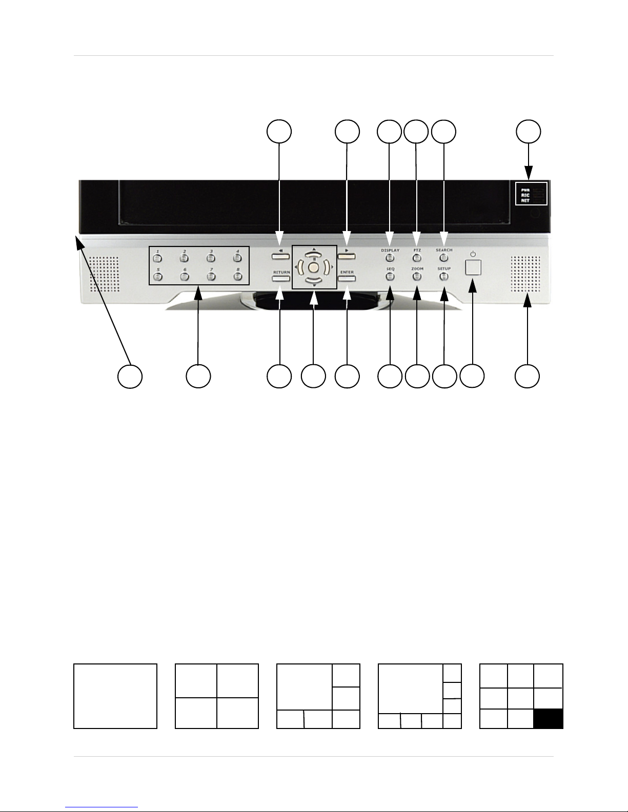
Front Panel
1. REW BUTTON - Reverses the playback of the currently displayed Video
2. FF BUTTON - Fast forwards the playback of the currently displayed Video
3. DISPLAY - Changes the onscreen Camera display:
• Single - Displays a single camera onscreen
• Quad - Displays 4 cameras onscreen
• 6 Camera Display - Displays 6 cameras onscreen. One main camera is displayed in the top
left corner, and 5 other cameras frame the bottom and right side.
• 8 Camera Display - Displays 8 cameras onscreen. One main camera is displayed in the top
left corner, and 7 other cameras frame the bottom and right side.
• 8 Camera Display(2) - Displays 8 cameras onscreen in a grid pattern.
123456
8910 11 12 13 14 15 16
7
SINGLE QUAD 6 CAM 8 CAM 8 CAM (2)
11
Front Panel
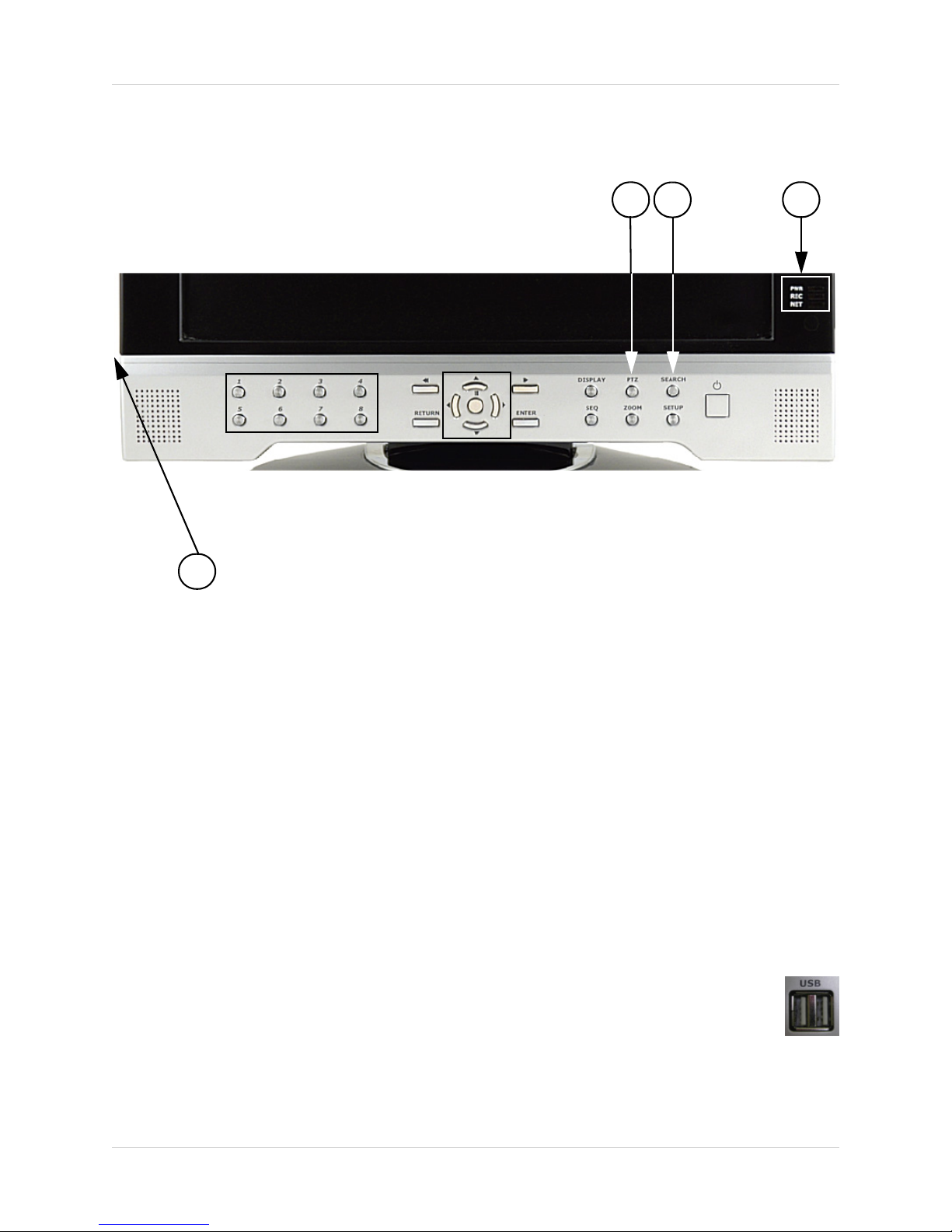
4. PTZ BUTTON - Accesses the PTZ (Pan/Tilt/Zoom) Menu. Refer to page 35 for Pan/Tilt/Zoom
options
NOTE: PTZ option will only work with PTZ type cameras (not provided with this unit). Visit the
Digimerge website at http://www.Digimerge.com for a full range of Pan/Tilt/Zoom Cameras.
5. SEARCH BUTTON - Opens the Search Menu to view previously recorded data. Refer to page
25 for detailed search options.
6. SYSTEM LEDs - Indicates the system status:
• PWR - Indicates that the system is ON/OFF (RED LED).
• REC - Indicates that the system is currently recording (when the RED LED is ON).
• NET - Indicates that the unit is connected to the Network (when the GREEN LED is ON).
7. USB PORTS (NOT SHOWN) - Provides connection ports for USB Flash Drives
(thumbsticks) and USB Hard Drives.
456
7

12
Front Panel
8. CHANNEL SELECT BUTTONS - Displays individual camera views. Also used to input the
system Password when accessing the Setup Menu.
9. RETURN BUTTON -
• Returns to a previous screen in Menu Mode.
• Exits from Menu Setup (when in the Main Menu screen). Exits from Search and PTZ Modes.
10. PLAYBACK / NAVIGATION CONTROLS -
• Controls the playback of video (Play / Pause / Fast Forward / Rewind), and controls the viewing
area in PTZ Viewing Mode.
• Navigates in the Main Menu, Search Menu
11. ENTER BUTTON -
• Accepts Selections in Search Mode, and Accepts Menu Changes and Applies in Menu Mode.
• Displays the System Information when in Channel View
910 11
8
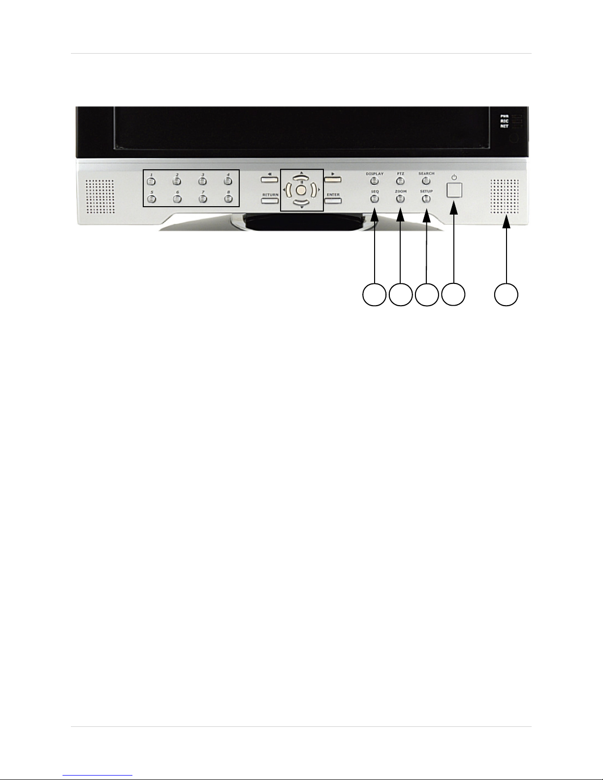
13
Front Panel
12. SEQ BUTTON - Used to Sequence between all camera locations in Full Screen mode (in
sequential order). To exit Sequence Mode, Press the SEQ button again
13. ZOOM BUTTON - This monitor is equipped with digital ZOOM. To utilize this feature proceed
as follows:
• Set the monitor to full screen mode for the desired channel
• Press the ZOOM button. ZOOM mode is now active
• Use the Navigation Buttons [ ÇÈÅÆ ] keys to move the area being captured in ZOOM
MODE.
• To exit ZOOM MODE, press the RETURN button.
14. SETUP BUTTON - Press to access the Main Menu Setup features. Refer to page 28 for a
detailed description of Menu Features.
15. POWER SWITCH - Press to turn the system display ON/OFF. Press and Hold the button for
6 seconds to turn the system ON/OFF (the default password is 1234).
16. SPEAKER - Provides sound from the Cameras. Only one camera will be audible at a time
through the speakers, however all cameras will continue to record sound.
12 13 14 15 16
14
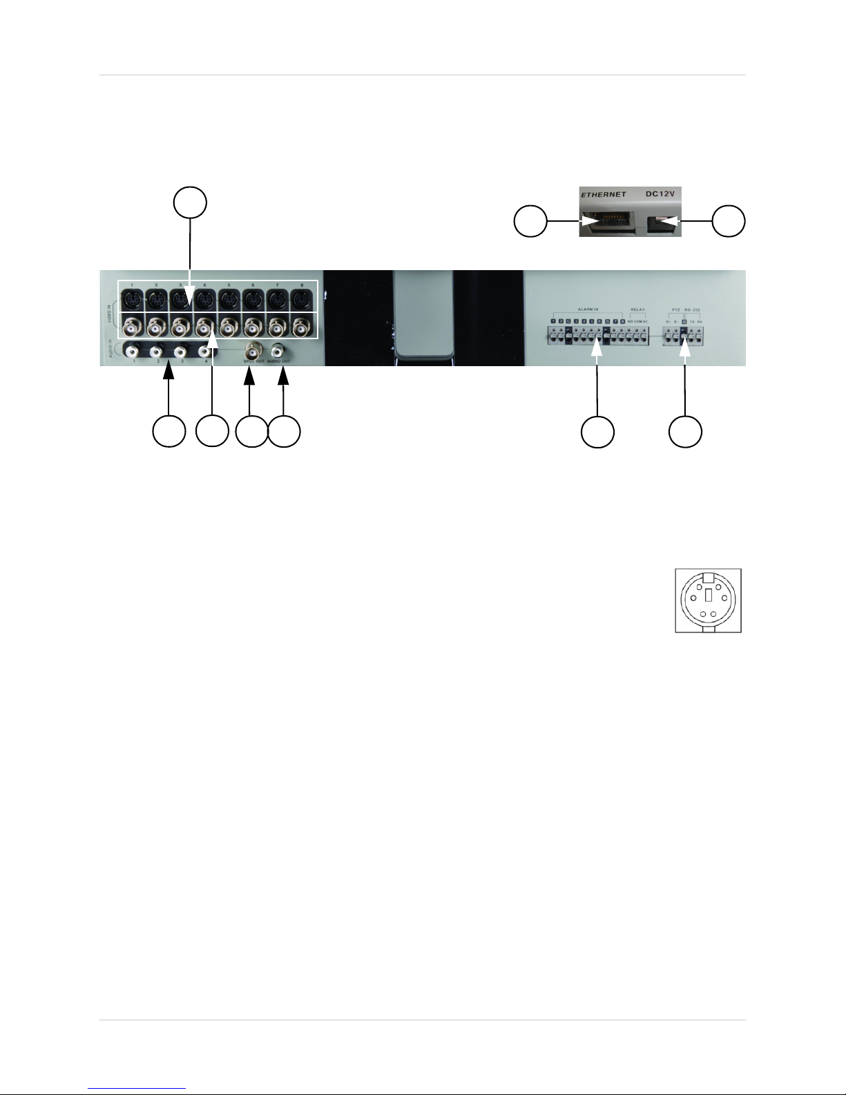
Rear Panel
Rear Panel
1. 6 PIN DIN CAMERA INPUTS - Channel 1-8 Camera inputs (for cameras with
6 Pin DIN connections).
Cameras with 6 Pin DIN connections draw power from the System - additional
power adapters are not needed.
2. RCA AUDIO INPUTS - Channel 1-4 Audio inputs (for BNC type cameras with standard RCA
Audio output)
3. BNC VIDEO INPUTS - Channel 1-8 camera inputs (used to connect Cameras with BNC
connection type). Cameras with BNC connections require an additional power adapter.
1
234
89
67
6 PIN DIN
5

15
Rear Panel
4. SPOT OUT - Video Output port to connect the unit to a secondary DVR or TV
5. AUDIO OUT - Audio Output port to connect the unit to a secondary DVR or TV
6. ALARM FUNCTION TERMINALS (INPUT/OUTPUT) - These terminals are used to connect
external alarm devices such as a motion sensor, door/alarm sensor, or time lapse VCR for Alarm
Recording. Refer to page 73 for Alarm Block Configuration.
7. PTZ CAMERA TERMINALS - These terminals are used to control PTZ (Pan/Tilt/Zoom) type
cameras. Refer to page 74 for PTZ Configuration
8. ETHERNET PORT - Located on the back of the unit, above the Alarm Block terminals. Connects
the monitor to a router for connection to the internet. Refer to page 59 for Remote Connection
setup.
9. DC INPUT - Located on the back of the unit, above the Alarm Block terminals. Connect the AC
power using the power cord provided with the unit from the monitor to an electrical outlet
89
67
45

16
Remote Control
Remote Control
Listed below is a quick reference for the Remote Control.
CHANNEL BUTTONS -
Press to select a
specific camera by
number
RETURN BUTTON -
Returns to the previous
selection in Menu Mode.
Exits the Menu Setup
when in the Main Menu.
DISP BUTTON -
Changes the Screen
Mode to Single, Quad, 6
or 8 camera views.
SEQUENCE -
Turns camera
Sequence Mode ON/
OFF.
POWER BUTTON -
Turns the system power
ON/OFF
SETUP BUTTON -
Opens the Main Menu
(system setup)
ENTER BUTTON -
Applies a configuration
change in Menu Mode.
SEARCH BUTTON -
Enters the Search
Menu.
ZOOM -
Zooms in on the current
image
NAVIGATION AND
PLAYBACK -
Controls the playback of
video.
Navigates in MENU and
SEARCH mode.
Adjusts the zoomed
area in ZOOM mode.
NOTE: All Buttons described above function the same as the Front Panel buttons - see pages
10-13 for detailed information. Buttons without descriptions do not provide functionality to this unit.
REMOTE ID* -
Configure when using
multiple systems.*
* If the REMOTE ID button is set incorrectly, the remote will not function. To reset the Re-
mote ID (when using only one system), Press the button, and then select the number 1.
Press ENTER to reset.
AUDIO SELECT -
Press to select an audio
channel. Press the
Audio select button,
then a channel 1~4.
VOLUME +
VOLUME -

17
Display Modes
Display Modes
Initial Loading Sequence
• Press the POWER button located on the front panel
of the Observation System to start the unit.
• The System will perform a Hard Drive check
NOTE: This unit includes a 160GB Hard Drive.
• The unit will initially load to a split screen view,
displaying all 8 cameras (if available).
Individual Camera Display
Each channel displays the Camera Name and Recording Status:
: Record
: Pre Record
C: Continuous
M: Motion
A: Alarm
NOTE: If a new HARD DRIVE is detected, the system will prompt you to FORMAT the drive.
If you do not choose to format the HARD DRIVE, the drive will not be detected by the system.
If you choose to FORMAT a drive in this way, the drive will no longer be readable by a regular
PC without using the HARD DRIVE VIEWER software included on the CD provided with this
unit.
18
Display Modes
Network Connectivity Indicator
The Network Indicators appear when a
remote connection is made to the unit via
the Remote Agent software, or through the
Internet Explorer Web Client:
• Green: Indicates that the network
connection is stable.
• Blue: Indicates that the network
connection is experiencing
difficulties.
• Red: Indicates that the network is
unstable.
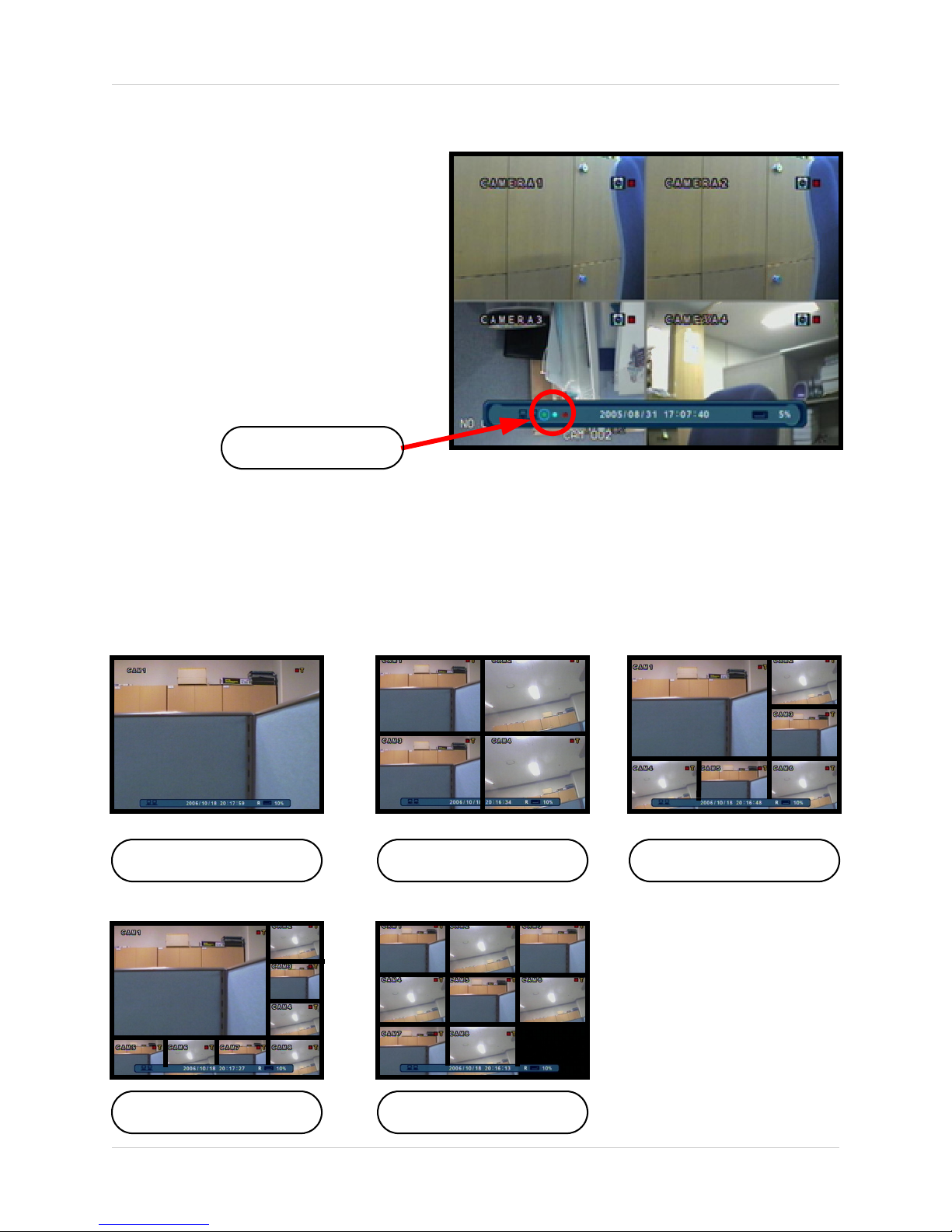
Display Modes
Cameras can be displayed in several different modes by pressing the Display Button on the front
panel of the system, or by pressing the SCR Button on the Remote Control:
Network Indicators
Single Channel Quad (4) Channel 6 Channel
8 Channel 8 Channel (Grid)
19
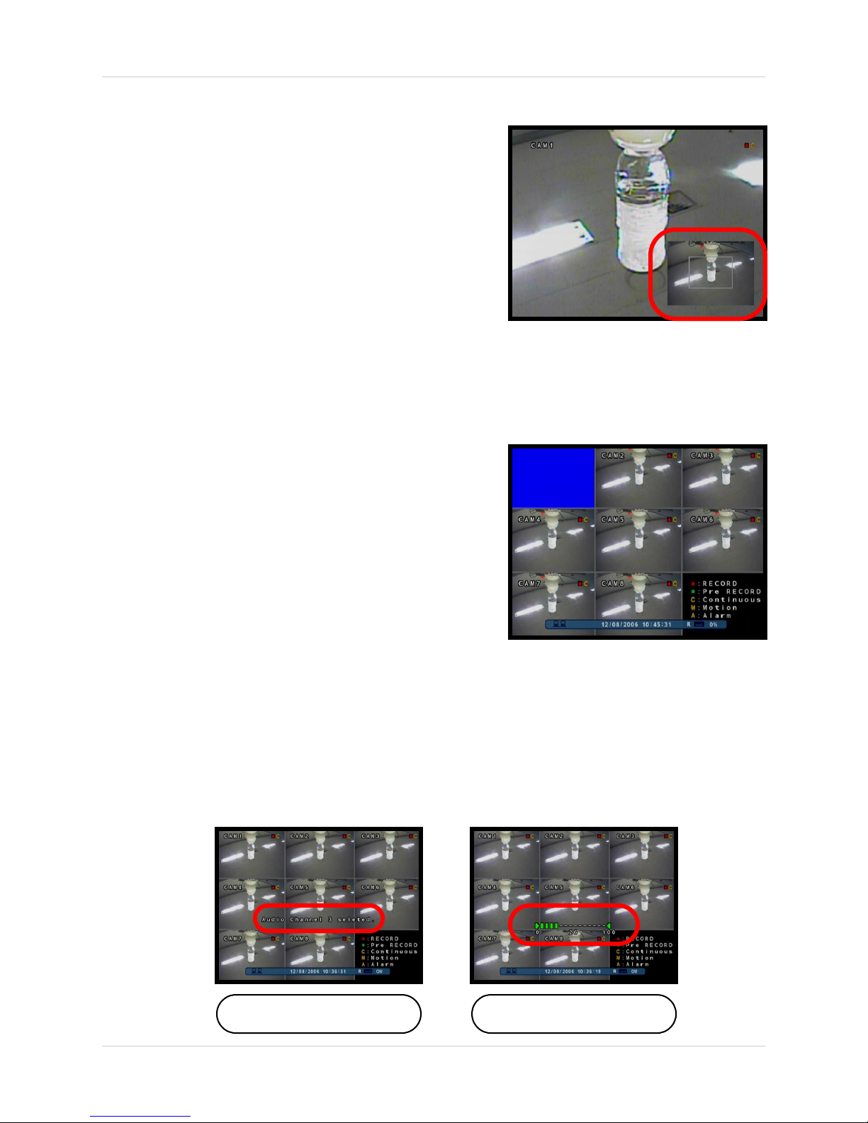
Display Modes
Zoom Mode
• Displays the Camera in ZOOM Mode.
• Use the Arrow keys to adjust the Zoom location.
• Press the Return key to exit ZOOM Mode.
Covert Camera Mode
• Displays the Camera in Covert Mode.
• The Camera is not displayed - an empty blue
screen is displayed instead of the Video.
• Covert cameras are configured from the Menu. .
Camera Volume Display Mode
• Displays the Camera currently sending Audio.
• The Camera Volume can be controlled using the up and down arrows.
Camera with Audio Volume Adjust

20
PTZ (Pan/Tilt/Zoom) & Focus Controls
PTZ (Pan/Tilt/Zoom) & Focus Controls
The PTZ / Focus Menus will only work with PTZ type cameras (not included):
NOTE: Make sure that the PTZ Settings are configured in the Menu before attempting to
use any of the PTZ Menu Functionality.
PTZ Control Screen Focus Control Screen
Press the PTZ Button on the front panel of
the system, or on the Remote Control to
access the PTZ Control Screen:
• The onscreen icons represent buttons
on the front panel and remote control
(up/down/left/right). The Camera can be
adjusted using these buttons
• Press the Return Button to exit PTZ
Mode.
Press the PTZ Button a second time to
access the Focus Control Screen:
• The onscreen icons represent buttons
on the front panel and remote control
(up/down/left/right). The Camera can be
adjusted using these buttons
zF: Indicates FOCUS
zI: Indicates IRIS
• Press the Return Button to exit PTZ
Mode.
Table of contents


