Digital Electronics Corporation PS365XA-HD40 User manual

1
Preface
The PS365XA-HD40 is the hard disk unit (HDD unit) for Pro-face’s PS-3650A/PS-
3710A Series (hereafter referred as the "PS-A") units. This 2.5 inch 40GB hard disk is
designed to be installed inside the PS-A unit.
Corresponding units: PS-3650A/PS-3651A Series, PS-3710A/PS-3711A Series
• Be sure to check that the PS-A unit’s power is disconnected before installing the unit, in
order to prevent an electrical shock.
• Do not attempt to modify or open the HDD unit, since it can cause a shock or fire.
• When installing the HDD unit, be sure to read this guide’s “3. Installation” section’s
information completely to ensure that the unit is correctly installed.
To prevent Accidents
• Since the HDD unit is a precision instrument, be sure it is neither hit by nor pressed
strongly against another object. After unpacking, be sure the unit is not dropped or
jolted during installation. Also, a PS-A unit built in to a larger piece of equipment (i.e.
operation panel) should be removed and packed separately prior to shipping.
• Be sure water, liquids or metal particles are not allowed to enter the HDD unit. Any of
these may cause either a breakdown or an electrical shock.
• Do not place or store this unit in a location where there is direct sunlight, excessive
heat, dust or vibration.
• Do not store or operate the HDD unit near chemicals, or where there are chemical fumes.
• Do not allow anyone other than Pro-face’s own service staff to perform maintenanceor
adjustments to the HDD unit.
• Do not move or shift the PS-A unit while the HDD unit is installed and the PS-A unit's
power is ON.
• Do not use the HDD unit in locations where corrosive gasses are present, since they
can lead to a hard disk breakdown.
• To prevent damage to your data, be sure to shut down the PS-A unit's OS before
turning OFF the main power.
• To prevent hard disk memory leaks, restart the OS periodically.
• A hard disk has a usage lifetime. In order to use your hard disk longer and more stable,
read through the attachment guide, “Instructions for Using the Hard Disk”.
• In order to extend the lifetime of the hard disk, Pro-face recommends you set the
Windows®[Control panel]-[Power Management option]-[Turn off hard disks]
selection to turn the hard disk off when the unit is not being operated. A setting of 5
minutes is recommended.
Unit Disposal
• When this HDD unit is disposed of, it should be done so according to your country’s
regulations for similar types of industrial wastes.
Essential Safety Precautions
2
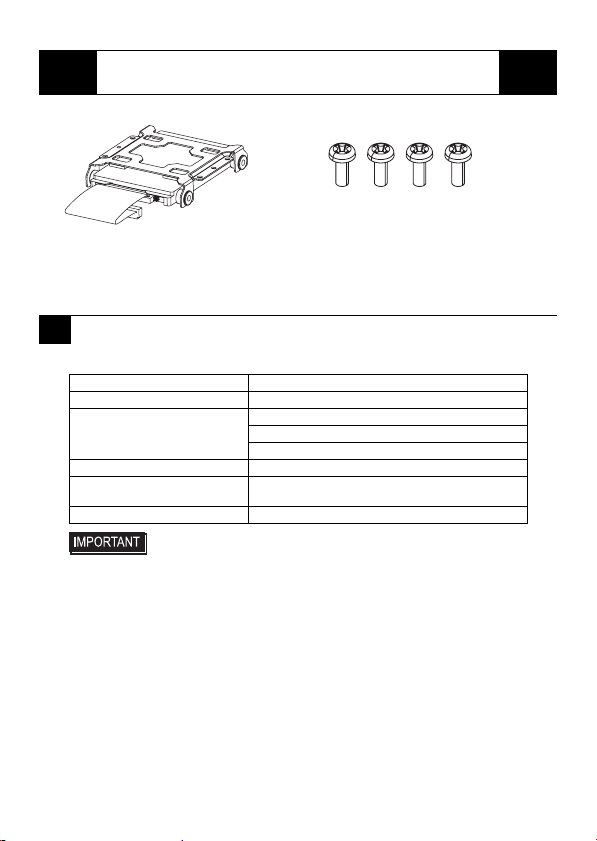
HDD Unit (1) (PS365XA-HD40) Attachment Screws (4)
Installation Guide (This Guide) Instructions for Using the Hard Disk (1)
Pro-face has taken the utmost care to insure the quality of this product when it was
shipped, however, should for any reason problems or damage have occurred during
shipping, please contact your Pro-face representative immediately for service.
Performance
Package Contents
1Hardware Specifications
Capacity 40GB
Average Seek time 12msec (TYP)
Power Consumption At Startup: 5.0W (MAX)
Read/Write: 1.8/1.8W (TYP)
During Wait: 0.2W (TYP)
Interface PATA
Operation Lifetime 5 years, or 20,000 operating hours,
whichever comes first
Weight Approx. 200g
• The HDD unit has a finite usage lifetime. Therefore, be sure to back
up all HDD data periodically or prepare a backup HDD unit.
• The HDD unit's lifetime will vary, depending on the usage
conditions and environment. The above value is calculated
assuming an ambient temperature of 20°C and 333 hours of
operation per month. (HDD access frequency of 20% or less)
• To use the hard disk longer by steady operation, read the attached
"Instructions for Using the Hard Disk" carefully.
3
Environmental
The specifications given here are for a HDD unit installed in a PS-A unit.
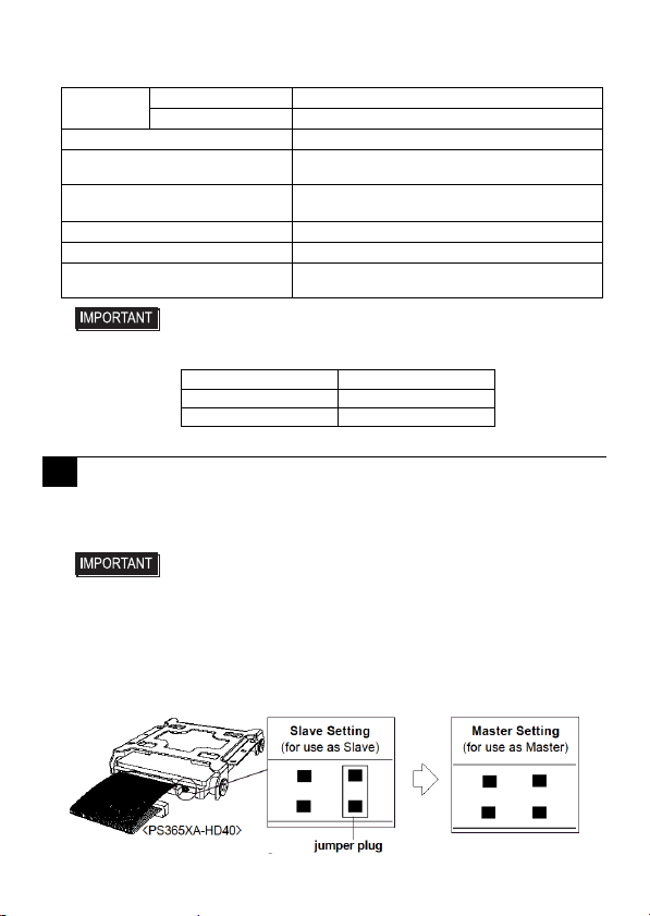
The PS365XA-HD40 is one of the Expansion Options for PS-A Series, when shipped, set
as the PS-A's Slave drive (Second Hard Disk).When using the PS365XA-HD40 as the
PS-A's Master drive, be sure to perform the following setup.
Operating
Temperature PS-3710A, PS-3650A +5°C to +50°C
PS-3711A, PS-3651A +5°C to +45°C
Storage Temperature -10°C to +60°C
Ambient Humidity 10%RH to 90%RH (No condensation)
(Wet bulb temperature: 29°C or less)
Noise Resistance
(via Noise Simulator) Noise Voltage: 1,500Vp-p (via noise simulator)
Pulse Width: 50ns, 500ns, 1µs
Electrostatic Discharge Immunity 6kV
Vibration Resistance 4.9m/s2(10Hz to 25Hz) (When Operating)
Shock Resistance 3290m/s2
(1ms, Half-sine shock pulse) (When Shipping)
• Using the HDD unit in an environment that is excessively hot and/or
humid will shorten the disk’s usage lifetime. A wet bulb temperature of
29
°C
or less is recommended. This is equivalent to the following data.
2Hard Disk Unit Settings
• If PS-A units have this HDD Unit as a built-in hard disk, the HDD
unit, when shipped, is set as the PS-A's Master. If set as the PS-A's
Slave, except for the jumper plug included, do NOT use any other
jumper plugs with the PS365XA-HD40, since it can cause a
malfunction or damage the unit.
• Pro-face’s PS-A Unit built-in Windows®XP Embedded and
PS365XA-HD40 should be used as the factory settings (CF card is
set to the PS-A's Master drive and HDD unit is set to the PS-A's
Slave drive).
Temperature Humidity
at 35°C no higher than 64%RH
at 40°C no higher than 44%RH
4
• Shock Danger! Be sure to unplug the PS-A unit from its power supply prior to
installing the HDD unit.
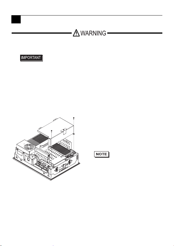
When attaching the HDD to the PS-3650A
3Installation
• Since the HDD unit is a precision instrument that has a low
resistance to shocks, be sure it is neither hit by nor pressed strongly
against another object when installing it.
• Even when the PS-A unit’s screen display disappears, the power
might be distributed inside (such as the “Standby” status etc). Be
sure to confirm that the power supply switch on the rear side of the
PS-A unit is OFF.
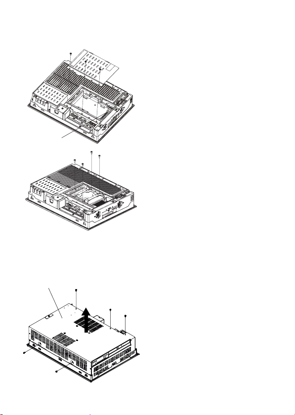
(1) Turn off the power switch of the PS-A
unit, remove the power cable. Put the
PS-A on the horizontal place while the
display side of it is downside.
(2) Unscrew the screws (2) from the
Expansion Board Cover, and remove
the Cover.
• When using the PCI
board, it is required to
remove the Expansion
Board Support first.
Then remove the
Expansion Board
Cover and the PCI
board.
5
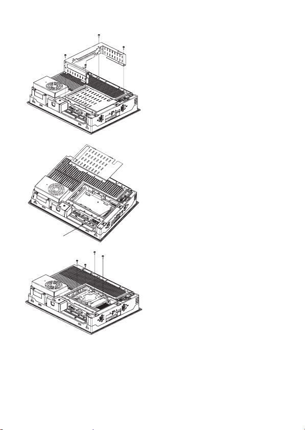
IDE I/F
(3) Unscrew the screws (4), which are
seen on the left figure, and remove the
Expansion Board Base.
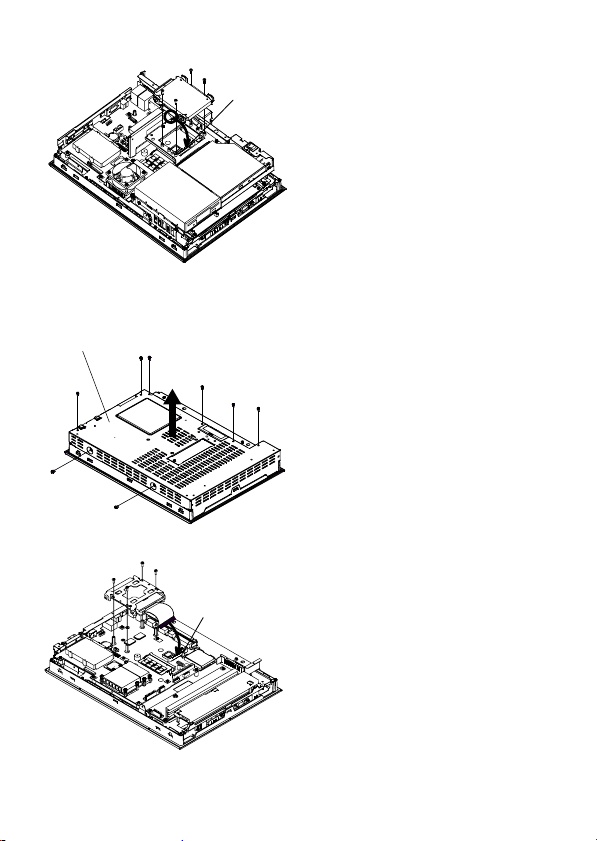
(4) Remove the IDE cover and plug the
HDD unit cable connector in the IDE’s
interface (Seen the figure on the left).
(5) Install the HDD unit like the left
figure, and fix it with the screws (4)
which are contained in your package.
The torque strength for the fixing
should be a range of 0.5 to 0.6 N•m.
(6) With opposite procedure above, set the
IDE cover, Expansion Board Base, and
Expansion Board Cover to the PS-A
unit, respectively.
6
When attaching the HDD to the PS-3651A
When attaching the HDD to the PS-3710A
IDE I/F
(1) Turn off the power switch of the PS-A
unit, remove the power cable. Put the
PS-A on the horizontal place while the
display side of it is downside.
(2) Unscrew the screws (3) of the IDE
cover and remove the IDE cover. Plug
the HDD unit cable connector in the
IDE’s interface (Seen the figure on the
left).
(3) Install the HDD unit like the left
figure, and fix it with the screws (4)
which are contained in your package.
The torque strength for the fixing
should be a range of 0.5 to 0.6 N•m.
(4) Place the IDE cover back and fix it
with the screws (3) of the IDE cover.
(1) Place the PS-A unit face down and
unscrew five (5) attachment screws.
(See diagram).
(2) Lift the PS-A unit’s Rear Cover off of
the PS-A unit.
PS-A unit’s Rear Cover
7
When attaching the HDD to the PS-3711A
(3) Insert the HDD unit cable connector
completely into the IDE I/F.
Attach HDD unit using four (4)
attachment screws.
The torque should be 0.5 to 0.6 N•m.
(4) Replace the PS-A unit’s Rear Cover
and reattach five (5) attachment
screws.
The torque should be 0.5 to 0.6 N•m.
IDE I/F
(1) Place the PS-A unit face down and
unscrew eight (8) attachment screws.
(See diagram).
(2) Lift the PS-A unit’s Rear Cover off of
the PS-A unit.
(3) Insert the HDD unit cable connector
completely into the IDE I/F.
Attach the HDD unit using four (4)
attachment screws.
The torque should be 0.5 to 0.6 N•m.
(4) Replace the PS-A unit’s Rear Cover
and reattach eight (8) attachment
screws.
The torque should be 0.5 to 0.6 N•m.
PS-A unit’s Rear Cover
IDE I/F

8
Inquiry
Do you have any questions about
difficulties with this product?
Please access our site anytime that
you need help with a solution.
http://www.pro-face.com/otasuke/
Please be aware that Digital Electronics
Corporation shall not be held liable by
the user for any damages, losses, or
third party claims arising from the uses
of this product.
©Copyright 2006 Digital Electronics Corporation. All rights reserved.
Digital Electronics Corporation
8-2-52 Nanko-higashi
Suminoe-ku, Osaka 559-0031
JAPAN
TEL: +81-(0)6-6613-3116
FAX: +81-(0)6-6613-5888
http://www.proface.com/
Note
Table of contents
Other Digital Electronics Corporation Storage manuals


