Digital Reference DR-4000 Series User manual

www.digital-reference.com
DR-4000 Series Professional UHF Wireless Systems
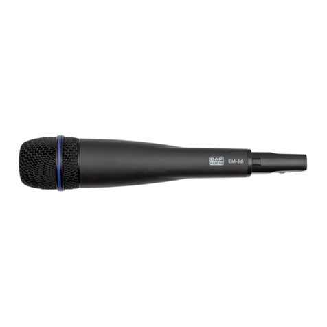
DR-4600 Handheld Dynamic Microphone System
DR-4500 Instrument Body Pack System
8868 Digital Ref 4600 Manual.indd 1 10/27/09 10:37:10 AM

DR-4000 Series Owner’s Manual
IMPORTANT SAFETY INSTRUCTIONS
THIS SYMBOL IS INTENDED TO ALERT THE USER TO THE PRESENCE
OF NON-INSULATED “DANGEROUS VOLTAGE” WITHIN THE PRODUCT’S
ENCLOSURE THAT MAY BE OF SUFFICIENT MAGNITUDE TO CONSTITUTE
A RISK OF ELECTRIC SHOCK TO PERSONS
THIS SYMBOL IS INTENDED TO ALERT THE USER TO THE PRESENCE
OF IMPORTANT OPERATING AND MAINTENANCE (SERVICING) IN-
STRUCTIONS IN THE LITERATURE ACCOMPANYING THE UNIT.
APPARATUS SHALL NOT BE EXPOSED TO DRIPPING OR SPLASHING
AND THAT NO OBJECTS FILLED WITH LIQUIDS, SUCH AS VASES,
SHALL BE PLACED ON THE APPARATUS.
1. Read all safety and operating instructions before using
this product.
2. All safety and operating instructions should be kept for
future reference.
3. Read and understand all warnings listed on the operating
instructions.
4. Follow all operating instructions to operate this product.
5. This product should not be used near water, i.e. a bathtub,
sink, swimming pool, wet basement, etc.
6. Use only a dry cloth to clean this product.
7. Do not install this product near any heat sources, such as
radiators, heat registers, stoves or any other apparatus
(including heat–producing amplifiers) that produces heat.
8. Do not defeat the safety purpose of the polarized or
grounding-type plug. A polarized plug has two blades with
one wider than the other. A grounding-type plug has two
blades and a third grounding prong. The wide blade or
the third prong are provided for your safety. If the provided
plug does not fit into your outlet, consult an electrician for
replacement of the obsolete outlet.
9. Protect the power cord being walked on or pinched,
particularly at plugs, convenience receptacles and the
point where they exit from the apparatus. Do not break the
ground pin of the power supply cord.
10. Only use attachments specified by the manufacturer.
11. Unplug this apparatus during lightning storms or when
unused for long periods of time.
12. Care should be taken so that objects do not fall and liquids
are not spilled into the unit through the ventilation ports or
any other openings.
13. CAUTION! Electrical shock can result from removal of
the receiver cover. Refer servicing to qualified service
personnel. No user-serviceable parts inside. Do not
expose to rain or moisture. The circuits inside the receiver
and transmitter have been precisely adjusted for optimum
performance and compliance with federal regulations. Do
not attempt to open the receiver or transmitter. To do so will
void the warranty, and may cause improper operation.
14. WARNING: To reduce the risk of fire or electric shock, do
not expose this apparatus to rain or moisture.
15. When a mains plug is used as the disconnect device, the
disconnect device shall remain readily operable.
This device complies with part 15 of the FCC Rules. Operation
is subject to the condition that this device does not cause
harmful interference.
This device complies with INDUSTRY CANADA R.S.S. 210,
en conformité avec IC: RSS-210/CNR210. Operation is
subject to the following conditions: 1) This device may not
cause harmful interference and 2) this device must accept
any interference received, including interference which may
cause undesired operation.
Notice to individuals with implanted cardiac pacemakers
or AICD devices:
Any source of RF (radio frequency) energy may interfere
with normal functioning of the implanted device. All wireless
microphones have low-power transmitters (less than 0.05
watts output) which are unlikely to cause difficulty, especially
if they are at least a few inches away. However, since a
“body-pack” mic transmitter typically is placed against the
body, we suggest attaching it at the belt, rather than in a shirt
pocket where it may be immediately adjacent to the medical
device. Note also that any medical-device disruption will
cease when the RF transmitting source is turned off. Please
contact your physician or medical-device provider if you have
any questions, or experience any problems with the use of this
or any other RF equipment.
8868 Digital Ref 4600 Manual.indd 2 10/27/09 10:37:10 AM

DR-4000 Series Professional UHF Wireless Systems
DR-4600 Handheld Dynamic Microphone System
DR-4500 Instrument Body Pack System
www.digital-reference.com
INTRODUCTION ....................................2
USING THIS MANUAL ...............................2
DR-4000 SERIES UHF WIRELESS SYSTEMS FEATURES ....2
DR-R40 RECEIVER SET-UP (QUICK START) ..............4
Attaching the Antennas..............................4
Connecting the Audio Output.........................4
Connecting the Power Adapter........................4
Powering the Receiver...............................4
Finding a Clean Frequency...........................4
TRANSMITTER SET-UP ...............................5
DR-T40 Handheld ..................................5
DR-T45 Body Pack .................................6
DR-R40 RECEIVER OPERATION .......................7
Front.............................................7
LCD Window......................................7
Back.............................................7
Rack-mounting the Receiver ..........................8
Installing Antennas .................................8
Powering the Receiver...............................8
Connecting the Audio Output.........................9
Powering On .....................................9
Audio Level and Peak LED Indicator....................9
DR-R40 Receiver Navigation ........................10
Frequency Selection ...............................10
IR Sync .........................................10
Adjusting the Audio Output ......................... 11
Adjusting the Squelch ..............................11
TRANSMITTER OPERATION..........................12
Handheld .......................................12
Body Pack ......................................12
Batteries.........................................13
Powering On/Off .................................14
Instrument Use....................................14
DR-T40/DR-T45 Transmitter Menu Navigation ..........15
Programming the Transmitter to the Selected Channel.....15
IR Sync for DR-T40 Handheld Transmitter ..............15
IR Sync for DR-T45 Body Pack Transmitter ..............16
Setting the Transmitter Power Level....................17
Setting the Transmitter Input Volume Level ..............17
CAUTION AND TROUBLESHOOTING.................18
Feedback........................................18
No or Low Audio .................................18
RF Interference and Finding Open Channels ...........19
TIPS ..............................................20
Antenna.........................................20
Transmitter .......................................20
Batteries.........................................20
Receiver.........................................20
SERIES RF FREQUENCY TABLE .......................21
SPECIFICATIONS...................................24
System Specifications ..............................24
DR-R40 Receiver Specifications ......................24
DR-T40 Handheld Transmitter Specifications ............24
DR-T45 Body Pack Transmitter Specifications ...........25
Frequency Plan ...................................25
Accessories . . . . . . . . . . . . . . . . . . . . . . . . . . . . . . . . . . . . . . 25
WARRANTY .......................................25
TABLE OF CONTENTS
8868 Digital Ref 4600 Manual.indd 3 10/27/09 10:37:10 AM

DR-4000 Series Owner’s Manual
2
INTRODUCTION
Thank you for choosing a Digital Reference’s wireless system. The DR-4000 series offers clear-channel, frequency-
agile UHF band operation for interference-free performance. It also delivers 1000 user-selectable channels,
frequency-synthesized in 10 groups and 100 channels on the US frequency band 672MHz–697MHz. This new
system feature proprietary companding and low-noise circuitry for an industry-best 120dB dynamic range, and the
clearest sound available in wireless today.
USING THIS MANUAL
This manual will explain the benefits of the DR-4000 Series while taking you through step-by-step operations. Each
section will give you detailed information about each unit. The Quick User Controls Guide, System Specifications,
and Servicing Information are also included for these systems:
DR-4000 Series Systems
DR-4600 Handheld Dynamic Microphone System
DR-4500 Instrument Body Pack System
DR-4000 SERIES UHF WIRELESS
SYSTEMS FEATURES
•State-of-the-art PLL UHF performance with 120dB
dynamic range and up to 300 feet of line-of-
sight operation.
•1000user-selectableUHFfrequenciesperband.
•TrueDiversitycircuitry(with2completefrontends)to
maximize range and eliminate dropouts.
•Advanced RF ltering for simultaneous operation
of multiple DR-4600/DR-4500 systems in the
same location.
•Front panel touch control buttons with user-friendly
LCD configuration menus.
•IR (Infra-Red) data download from receiver to
transmitter for GROUP/CHANNEL programming.
•Separate audio LED bar graph display provides
instantaneous audio level status from a distance.
•Front panel—Backlit LCD display indicates selected
audio output VOLUME level, GROUP, CHANNEL, RF
signal strength meter, and A/B Diversity antenna status.
8868 Digital Ref 4600 Manual.indd 2 10/27/09 10:37:10 AM

DR-4000 Series Professional UHF Wireless Systems
DR-4600 Handheld Dynamic Microphone System
DR-4500 Instrument Body Pack System
www.digital-reference.com 3
•Back panel—Balanced XLR Mic level, Unbalanced
1⁄4” Line level audio output jacks, Squelch control,
BNC RF connectors for dual removable antennas,
and DC input jack.
•Externallypowered(adapterincluded).
•Includesplasticcarrycase.
•Rack-mountable, rugged all-metal housing with
optional DR40RM1 single or DR40RM2 dual (side-
by-side) rack mount kits.
•All-metal transmitter construction for both Handheld
and Body Pack.
•SelectableRFpoweroutput.
NOTE: DR-T40 and DR-T45 transmitters feature LCD displays
indicating selected GROUP, CHANNEL and BATTERY Level
status. In addition, selectable HIGH/LOW RF Power optimizes
distance operation depending on application. Operation with
2 AA batteries (alkaline or rechargeable NiMH) ensures a reliable,
economical battery life.
DR40RM2
Optional
AC/DC adapter 15VDC/400mA
DR40RM1
Optional
8868 Digital Ref 4600 Manual.indd 3 10/27/09 10:37:11 AM

DR-4000 Series Owner’s Manual
4
Attaching the Antennas
•Attach the antennas to the two BNC connectors
located on the rear of the receiver.
•Forbestresults,placeantennasatopposing
45 degree angles.
Connecting the Audio Output
To connect to the DR-R40, attach either:
•AbalancedXLRmicrophonecabletothesound
system mixer input.
•Anunbalancedinterconnectcabletothesound
system mixer input.
•Anunbalanced¼instrumentcabletothe
instrument amplifier.
Connecting the Power Adapter
•ConnecttheDCpowersupplytotherearoftheReceiver.
•PluginpowersupplyintoanACoutletorpowerstrip.
Powering the Receiver
•Press the POWER button on the right side of the
receiver front panel.
•TheblueLCDscreenwillpoweron.
Finding a Clear Frequency
•ThedefaultsettingforDR4600HandheldisGROUP 8
CHANNEL 00. DR4500 Instrument system is GROUP
3 CHANNEL 00.
•ExaminetheRFmeterabovetheVOLUMElevelinthe
Blue LCD Screen.
•IftherearenoRFmeterbars,pressSET button to exit
programming and proceed to Transmitter Set-Up.
•If there are multiple RF bars, interference is present
and a clean channel must be found:
– Press the SET button to select GROUP, CHANNEL,
or VOLUME.
– Select GROUP and use the UP/ DOWN
buttons to select a new GROUP without RF bars.
– Select CHANNEL and use the UP/ DOWN
buttons to select a new CHANNEL without RF bars.
– When you have identified a GROUP/CHANNEL
combination without RF bars, proceed to Transmitter
Set-Up.
DR-R40 RECEIVER SET-UP (QUICK START)
8868 Digital Ref 4600 Manual.indd 4 10/27/09 10:37:12 AM

DR-4000 Series Professional UHF Wireless Systems
DR-4600 Handheld Dynamic Microphone System
DR-4500 Instrument Body Pack System
www.digital-reference.com 5
TRANSMITTER SET-UP
DR-T40 Handheld
•Unscrew the body at the neck area between the
microphone and capsule.
•Slidethesleevedowntoexposethebatteryterminal.
•InserttwoAAbatteries,notingthepolarityinstructions
in the battery compartment.
•Closethesleeve.
•TurnthePowerswitchOn.TheLCDwindowwilllight
Blue for a few seconds.
•Locate the IR window on the back of the DR-T40
transmitter and hold it 4” in front of the IR window of
the Receiver.
•Press the Sync button on the Receiver and wait
4 seconds.
•The LCD window on the transmitter will briey
turn blue, and indicate the same CHANNEL/GROUP as
the Receiver.
•TheReceiver’sLCDwillshowRFmeterbars,andan
antenna icon.
•If sync fails, use the transmitter’s SET and UP
DOWN buttons to match the Transmitter’s GROUP/
CHANNEL to the Receiver’s GROUP/CHANNEL.
•Thewirelesssystemisnowreadyforuse. 4”
NOTE: Receiver IR window and transmitter IR port
must be facing each other.
8868 Digital Ref 4600 Manual.indd 5 10/27/09 10:37:12 AM

DR-4000 Series Owner’s Manual
6
DR-T45 Body Pack
•Pressthetwosidebuttonstoopenthelatchingdoorof
the Body Pack.
•Insert two AA batteries, noting that the + terminal
aligns with the metal tab, and the – terminal aligns
with the spring.
•TurnthePowerswitchtoMute.
•Holdtheopenbodypack4”infrontoftheReceiver’s
IR window, with the batteries facing the receiver.
•Press the Sync button on the Receiver and wait
4 seconds.
•The LCD window on the transmitter will briey turn
blue, and indicate the same GROUP/CHANNEL as
the Receiver.
•TheReceiver’sLCDwillshowRFmeterbars,and
an antenna icon.
•IfSyncFails,usethetransmitter’sSET
and UP/ DOWN buttons to the Receiver’s
GROUP/CHANNEL.
•TurnthePowerswitchtoOn.
•Thewirelesssystemisnowreadyforuse.
Body Pack
Body Pack Top View
4”
NOTE: Receiver IR window and transmitter IR port
must be facing each other.
8868 Digital Ref 4600 Manual.indd 6 10/27/09 10:37:13 AM

DR-4000 Series Professional UHF Wireless Systems
DR-4600 Handheld Dynamic Microphone System
DR-4500 Instrument Body Pack System
www.digital-reference.com 7
DR-R40 RECEIVER OPERATION
Front
1. AF LED Tree and Peak Indicator
2. LCD Display
3. SET Button
4. UP/ DOWN buttons
5. IR Transmit Window
6. SYNC Button
7. Power On/Off Button
LCD Window
8. Diversity Receiver A/B Indicator
9. RF Signal Meter
10. Frequency GROUP
11. Frequency CHANNEL
12. Output VOLUME Level
Back
13. DC Power Input Jack
14. BalancedXLRMicrophoneLevelOutput
15. SQUELCH Control
16. Unbalanced 1/4” Line Level Output
17. BNC Antenna Input Connectors
18. DC Power Supply
19. Antennas
20. Optional DR40RM1 Single Unit
Rack Mount Kit
21. Optional DR40RM2 Dual Unit
Rack Mount Tray
13 14 15 16 17 17
18 19 20 21
1 2 3
10
4
11
5
12
6 7
8 8
9
8868 Digital Ref 4600 Manual.indd 7 10/27/09 10:37:14 AM

DR-4000 Series Owner’s Manual
8
Rack-mounting the Receiver
There are two options available to rack-mount
the DR-R40:
Single mounting: Attach the optional DR40RM1 to each
side and tighten with supplied screws (as shown).
Side-by-side mounting: Attach the optional DR40RM2
Dual Receiver Rack Tray to the bottom of both receivers
and tighten with supplied screws (as shown).
NOTE: Do not mount the receiver on a rack directly above an
amplifier or other source of high heat as this could affect the
performance of the DR-R40. In any rack configuration, always
ensure adequate airflow and heat dissipation. Do not mount the
receiver directly above or below a digital device such as an effect
processor or CD player. Digital emissions can reduce RF range.
Installing Antennas
Connect the two antennas included with your system to
the two RF Connectors located on the back of your DR-
R40 receiver. Optimal antenna positions are 45 degrees
from the receiver, while being 90 degrees from each
other. For maximum range, it is always best to maintain
line of sight between the receiver antennas and the
transmitter whenever possible (i.e. no obstructions).
Powering the Receiver
To power the receiver, plug the provided AC/DC adapter
15VDC/400mA into the DC Input Jack on the back of
the receiver. Now plug the adapter into an AC outlet.
NOTE: Any 15-18VDC source with minimum 400mA capacity can
be used in lieu of an adapter.
DR40RM1
Optional
DR40RM2
Optional
AC/DC adapter 15VDC/400mA
8868 Digital Ref 4600 Manual.indd 8 10/27/09 10:37:14 AM

DR-4000 Series Professional UHF Wireless Systems
DR-4600 Handheld Dynamic Microphone System
DR-4500 Instrument Body Pack System
www.digital-reference.com 9
Connecting the Audio Output
ForbalancedXLRoutput,pluganXLRmicrophonecable
into the BALANCED MIC OUT socket and connect the
other end into your mixing board. For unbalanced
output, plug an audio cable with a 1⁄4” mono plug into
the UNBALANCED LINE OUT jack and plug the other
end into your mixing board. For an instrument transmitter
system (DR-4500), connect the UNBALANCED LINE
OUT directly to your instrument amp or preamp. At
maximum receiver volume setting, the system output is
approximately+4dBhigherthanadirectcord-to-amp
connection.
NOTE: To avoid possible sound system damage, make sure the
amplifier or mixing board volume is at its minimum level before
plugging in the receiver.
Powering On
To turn the unit on, press the Power Switch for
2 seconds. The LCD will light and show the GROUP,
CHANNEL assignment, RF Level Meter, Diversity, and
Output Volume. The 5-segment AF LED TREE will display
the received audio level when the transmitter is activated
and audio transmitted.
To turn the unit off, press the Power Switch for 3 seconds
and release.
At power-off, the DR-R40 receiver will store the last
settings entered and display them at power-on. This can
be reprogrammed to any new GROUP/CHANNEL,
or VOLUME level. The default setting for DR4600
Handheld is GROUP 08 CHANNEL 00 and VOL 63.
DR4500 Instrument system is GROUP 03 CHANNEL
00 and VOL 63.
Audio Level and Peak LED Indicator
The DR-R40 receiver has a 5-segment AF LEVEL LED
display that lights up sequentially to indicate the
audio signal’s level from the transmitter. Occasional
ickeringofthetop(red)PeakLEDonloudinputstothe
transmitter is normal. If the Peak LED is lit continuously,
decrease the input audio level to the transmitter as this
may overload distortion.
8868 Digital Ref 4600 Manual.indd 9 10/27/09 10:37:14 AM

DR-4000 Series Owner’s Manual
10
DR-R40 Receiver Navigation
The SET button is used to scroll between the GROUP,
CHANNEL, and VOLUME settings. Press the SET button
untilthedesiredfunctionashes.Usethe UP/ DOWN
buttons to select a new value. Press and hold the UP/
DOWN buttons to scroll through values more quickly.
Once the new value is selected, press the SET button
to store, or wait 10 seconds for the display to time out.
The new value is now saved.
Frequency Selection
Choose the DR-R40’s operating frequency by selecting
one of 10 GROUPS, and one of 100 CHANNELS
per group. See page 20 for a Master Frequency list
by GROUP/CHANNEL. Press the SET button twice to
select the GROUP, then use the UP/ DOWN buttons
to change the value. Press the SET button again to
select CHANNEL, and use the UP/ DOWN buttons
to change the value.
See the RF Interference and Finding Open Channels
section (Page 19) for additional help in finding open
channels or operating multiple DR-4000 systems.
IR Sync
The SYNC Button is used to download GROUP/
CHANNEL frequency information from the receiver
to the transmitter using IR (Infrared) Sync. Hold the
transmitter’s IR window 4” in front of the Receiver. Press
theIRSyncButtonandtheIRLEDwillashquickly.This
LED indicates IR transmission is in progress. Press the
SETButtonagaintostopashing,orwait20seconds,
as it will stop automatically. Successful sync is confirmed
when the Transmitter LCD screen ashes blue and
the GROUP/CHANNEL settings are the same as
the receiver’s.
4”
8868 Digital Ref 4600 Manual.indd 10 10/27/09 10:37:15 AM

DR-4000 Series Professional UHF Wireless Systems
DR-4600 Handheld Dynamic Microphone System
DR-4500 Instrument Body Pack System
www.digital-reference.com 11
Adjusting the Audio Output
The Receiver Output Volume is displayed in the lower
right corner of the LCD display. Output level can be
adjusted by pressing the SET button 3 times to scroll
to the Volume setting. When the Volume indicator is
ashing,usethe UP/ DOWN buttons to select a
volume setting between 0–63. The Volume indicator
willstopashingafter10secondsandthenewvalue
is stored.
Adjusting the Squelch
SQUELCH adjusts the Receiver’s sensitivity to RF signals.
A high SQUELCH setting typically reduces the chance
of RF interference, but lowers the useable operating
distance. A low SQUELCH setting typically increases
operating distance, but increases the possibility of
unwanted interference.
The SQUELCH control on the DR-R40 receiver
simultaneously controls both the A and B True Diversity
receiver sections. The control should be adjusted
counterclockwise to the minimum RF squelch setting at
which the RF Level Meter and the Diversity Indicator will
remain lit while your transmitter is in normal use, up to
its anticipated maximum operating range. However, in
areas of high RF activity, the squelch control may need
to be adjusted clockwise.
If the transmitter is off and both the receiver signal and
diversityindicatorsareickeringorstaylitcontinuously,
the SQUELCH should be adjusted to a higher level
(clockwise for less mute sensitivity level). Be careful
not to select too high a clockwise setting, as this may
reduce the operating range below what is needed.
A range walk test will help in selecting the proper
level. If the range is not critical, note that a clockwise
(max SQUELCH) setting will also yield a quieter mute
function, which might be desired in certain applications.
Also note that the SQUELCH level is factory preset
at maximum sensitivity and operating range (i.e. turn
counterclockwise to MIN).
8868 Digital Ref 4600 Manual.indd 11 10/27/09 10:37:15 AM

DR-4000 Series Owner’s Manual
12
TRANSMITTER OPERATION
Handheld
1. Mic Capsule
2. Collar Joint
3. LCD Display
4. UP/ DOWN Buttons
5. SET Button
6. RF Transmit Power
7. ON/OFF Switch
8. IR Sync Receiver
9. Battery Compartment
10. Metal Battery Cover
LCD Window
11. RF Group
12. RF Channel
13. Battery Meter (5 Segment)
14. Input Volume Level
Body Pack
1. 3.5mm Locking Input Jack
2. ON/MUTE/OFF Switch
3. Antenna
4. LCD Display
5. IR Sync Receiver
6. RF Transmit Power
7. UP/ DOWN Buttons
8. SET Button
9. Battery Compartment
10. Latching Battery Compartment Door
LCD Window
11. RF Group
12. RF Channel
13. Battery Meter (5 Segment)
14. Input Volume Level
FRONT VIEW
1 2 3 4 5 67
10
BACK VIEW
9
10
8
13
12
1411
1 2
7
3
8
10
9
4
5
6
13
12
14
11
8868 Digital Ref 4600 Manual.indd 12 10/27/09 10:37:16 AM

DR-4000 Series Professional UHF Wireless Systems
DR-4600 Handheld Dynamic Microphone System
DR-4500 Instrument Body Pack System
www.digital-reference.com 13
Batteries
The DR-T40 and DR-T45 require 2 AA size batteries.
•DR-T40 Handheld Transmitter: Turn clockwise until
loose and slide down, exposing the battery holder.
Insert 2 fresh AA batteries according to the correct
polarity (indicated on the transmitter body). Screw
the battery cover back onto the microphone, making
sure it is securely tightened.
•DR-T45 Body Pack Transmitter: Open the battery
compartment cover by gently pressing the two latches
centered on the side of the unit, and gently pull the
latching door open. Insert the batteries, noting that
+terminalalignswiththemetaltab,andthe–terminal
aligns with the spring.
Fresh alkaline batteries can last up to 8–10 hours
of operation. To ensure optimum performance, we
recommend you replace batteries after 6–8 hours of
use. The battery meter has 5 bars to indicate battery
strength. As the batteries weaken, fewer bars will show
untiltheBATTiconbeginstoash.Topreservebattery
life, turn the transmitter off when not in use.
8868 Digital Ref 4600 Manual.indd 13 10/27/09 10:37:16 AM

DR-4000 Series Owner’s Manual
14
Powering On/Off
•DR-T40HandheldTransmitter:SlidethepowerON/
OFF Switch to the ON position.
•DR-T45BodyPackTransmitter:SlidethepowerON/
MUTE/OFF Switch to MUTE for audio standby, and
ON to transmit sound.
The LCD backlight will indicate that the unit is now on.
After 10 seconds, the backlight will automatically turn
off to conserve battery life. The GROUP/CHANNEL
(LCD-G/LCD-C) and the BATT (LCD-B) indicator icons
stay on during normal operation.
To turn the transmitter off, slide the Power ON/OFF
switch to the OFF position. No LCD or backlight is lit
and the unit will turn off.
NOTE: The RF Level Meter (LCD-RF) and the Diversity A/B
Indicator (LCD-D) on the receiver’s LCD display should be on
during normal operation.
Instrument Use
Secure the instrument cable’s connection by lining up
the 3.5mm mini connector’s slot while turning the ring
to lock in. To activate the audio, slide the POWER
OFF/MUTE/ON switch to the ON position. Adjust the
volume on the receiver for one-to-one unity gain with a
hardwired cord or select up to an added 4-5dB boost
by adjusting the receiver volume to maximum for use
with guitars and bass guitars.
NOTE: The audio level should be adjusted when using any
hardwired cord.
Body Pack Top View
8868 Digital Ref 4600 Manual.indd 14 10/27/09 10:37:16 AM

DR-4000 Series Professional UHF Wireless Systems
DR-4600 Handheld Dynamic Microphone System
DR-4500 Instrument Body Pack System
www.digital-reference.com 15
DR-T40/DR-T45 Transmitter Menu Navigation
The SET button is used to scroll between the GROUP
and CHANNEL settings. Press the SET button until
the desired function is ashing. Then use the UP/
DOWN buttons to select a new value. Press and hold
the UP/ DOWN buttons to scroll through values
more quickly. Once the new value is selected, press the
SET button to store, or wait 10 seconds for the display
to time out. The new value is now saved.
Programming the Transmitter to the
Selected Channel
The Transmitter must be set to the same GROUP/
CHANNEL setting as the corresponding receiver. The
Transmitter can be programmed manually using the
SET or UP/ DOWN buttons, or automatically using
IR Sync.
IR Sync for DR-T40 Handheld Transmitter
•TurnthePowerswitchON. The LCD window will turn
blue for a few seconds.
•Locate the IR window on the back of the DR-T40
transmitter and hold it 4” in front of the IR window of
the Receiver.
•Press the SYNC button on the Receiver and wait
4 seconds:
–The LCD window on the transmitter will briey
light blue, and indicate the same CHANNEL/
GROUP as the Receiver.
– The Receiver’s LCD will show RF meter bars, and an
antenna icon.
•Thewirelesssystemisnowreadyforuse.
4”
8868 Digital Ref 4600 Manual.indd 15 10/27/09 10:37:16 AM

DR-4000 Series Owner’s Manual
16
IR Sync for DR-T45 Body Pack Transmitter
•TurnthePowerswitchtoMUTE.
•Holdtheopenbodypack4”infrontoftheIRwindow’s
Receiver, with the batteries facing the receiver.
•Press the SYNC button on the Receiver and wait
4 seconds:
–TheLCDwindowonthetransmitterwillbrieyturn
blue, and indicate the same CHANNEL/GROUP as
the Receiver.
– The Receiver’s LCD will show RF meter bars, and an
antenna icon.
– If Sync fails, use the transmitter’s SET and UP/
DOWN buttons to match the Transmitter GROUP/
CHANNEL to the Receiver GROUP/CHANNEL.
•TurnthePowerswitchtoON.
•Thewirelesssystemisnowreadyforuse.
NOTE: The IR link is infrared light and works best when this data
transfer is accomplished in a light-shielded or darker environment.
As such, the IR may not be successful in a brightly lit area. If the
transfer fails, repeat the procedure in a darker location. You can
also shield the link from outside light.
Body Pack Top View
4”
8868 Digital Ref 4600 Manual.indd 16 10/27/09 10:37:17 AM

DR-4000 Series Professional UHF Wireless Systems
DR-4600 Handheld Dynamic Microphone System
DR-4500 Instrument Body Pack System
www.digital-reference.com 17
Setting the Transmitter Power Level
DR-T40 and DR-T45 transmitters have two RF power
settings: High (25mW) and Low (2.5mW)
Unnecessary use of High Power mode can result in
increased intermodulation interference between multiple
wireless units. It’s recommended that you start with the
RF Transmit Power set to Low. Please note the following
guidelines when selecting RF Transmit Power:
•RFTransmitPowerisnotrelatedtosoundquality.
•LowPowerallowsforagreaternumberofsimultaneous
systems on air, and will not overload the receiver when
the distance between transmitter and receiver is close
(i.e. a performer standing in front of a guitar amp).
•HighPowerallowsforgreatertransmissiondistance,
but reduces the number of simultaneous systems on
air, and can overload the receiver at close distances.
•Only use High Power mode if greater distance is
required over the Low Power setting.
Setting the Transmitter Input Volume Level
The DR-T40 and DR-T45 transmitters feature an Input
Volume attenuation adjustment in the transmitter LCD
screen. This Input Volume attenuation adjustment reduces
the transmitter’s input sensitivity in -10dB increments.
•ThedefaultInput Volume forthe DR-T40 handheld
transmitter is -10dB.
•ThedefaultInputVolumefortheDT-T45bodypack
is 00dB.
•TheoptimumaverageAFlevelonthereceivedshould
be should be between 3 – 4 Green lights.
•Input Volume shouldbe reduced ifthe receivers AF
Level is consistently hitting the red, and/or the sound
is constantly distorted.
•The signal produced by loud singers or talkers may
need to be attenuated.
•Instrumentswithactivepick-upsystemsmayneedto
be attenuated.
8868 Digital Ref 4600 Manual.indd 17 10/27/09 10:37:17 AM

DR-4000 Series Owner’s Manual
18
CAUTION AND
TROUBLESHOOTING
Feedback
Take care in selecting PA volume, transmitter location,
and speaker placement so that acoustic feedback
(howling and screeching) is avoided. Please also note
the pickup pattern characteristics of the microphone
selected. Unidirectional mics are more resistant to
feedback. However, they are better at picking up sound
sources that are directly in front of the mic. Also, mics that
are farther from a sound source require more acoustic
gain, and thus are more prone to feedback than close-
source mics (i.e. handheld).
The following examples demonstrate proper and
improper microphone placement:
1. Good Mic Placement. The microphone is not in
the direct path of the loudspeaker, and the stage
monitor is pointed at the null point of the cardioid
microphone pattern.
2. Poor Mic Placement. The microphone is positioned
in front of the loudspeaker, and prone to feedback.
3. Poor Mic Placement. The microphone is pointed
directly at the monitor speaker, and prone
to feedback.
No or Low Audio
If you are not getting audio through the system, carefully
check all setups.
•Notethatthereceiverandtransmittermustbesetto
operate on the same RF CHANNEL.
•For DR-T45 Body Pack transmitters, conrm that
the POWER OFF/MUTE/ON switch is not in the
MUTE position.
•IfusingtheUNBALANCEDLINE LEVELOUTofthe
receiver, make sure the Volume setting in the Receiver
LCD panel is set high enough.
1.
✔
2.
✖
3.
✖
8868 Digital Ref 4600 Manual.indd 18 10/27/09 10:37:18 AM
Table of contents

