Dingo Tools 52CC User manual

1

2
DINGO TOOLS BRUSHCUTTER
Contents of Booklet
Warnings/Product Check List Page 2
What is in Your box/Assembly Page 3
Blade Assembly/Connecting Bars Page 4
Attaching Bumper Head Page 5
Attaching Blades Page 6
Opening and Closing Whipper
Snipper Head Page 7
Starting Sequence Page 8
How to mix fuel Page 9
Adjusting Idle Screw Page 10
Cutting Operation Page 11
Before Using This Unit:
Please Read the Operator’s manual carefully.
Check that the Cutting equipment is correctly assembled
(please read and follow instructions on Page 4)
Start the Unit and check the carburettor adjustment (Please
check Page 8 for this step if needed)
Always Wear Eye, Head and Ear Protectors when
Using This Unit.
Keep all Children, bystanders and helpers 15m (50ft) away
from Unit. If anyone approaches you, stop the engine and
cutting attachment immediately.
Gloves, Safety Goggles and ear muffs and Slip and Sturdy
Footwear should be worn at all times when operating
tools or Machinery.
15m (50ft)
ALWAYS MAINTAIN THIS BRUSHCUTTER ACCORDING TO THE
OWNER’S MANUAL AND FOLLOW THE RECOMMENDED SCHEDULED
MAINTENANCE.
NEVER MODIFY OR DISABLE ANY OF THE BRUSHCUTTER
SAFETY DEVICES.
ALWAYS USE GENUINE PARTS AND ACCESSORIES WHEN REPAIRING
OR MAINTAINING THIS MACHINE. DO NOT MAKE UNAUTHORIZED
MODIFICATIONS OR SUBSTITUTIONS. NEVER ALLOW THE ENGINE
TO RUN AT HIGH RPM WITHOUT A LOAD. DOING SO COULD
DAMAGE THE ENGINE.
WHEN TRANSPORTING THE MACHINE IN A VEHICLE, TIE IT DOWN
SECURELY TO PREVENT DAMAGE AND FUEL SPILLAGE.
ALWAYS CLEAR YOUR WORK AREA OF TRASH OR HIDDEN DEBRIS
TO HELP ENSURE GOOD FOOTING.
KEEP THE MACHINE PROPERLY ADJUSTED
KEEP THE MACHINE AS CLEAN AS POSSIBLE. KEEP IT FREE OF LOOSE
VEGETATION, MUD ETC.

3
STANDARD COMPONENTS
A. Bracket and 2 bolts for Guard
B. Nylon Cutter and Screw
C. Hex Screw (for assembly of Airfilter)
D. 2x plastic ties
E. Tools for Assembly
WHAT IS IN YOUR BOX
B
D
DA
AA
E E
EE
C
ACCESSORIES
F. Handle Bar Attachment G. Throttle Control
J. Bar Assembly Bracketi. Brushcutter
H. Airfilter
C. Hex screw for Air filter on the motor
K. Shoulder Strap
L. Guard
F
G
J
i
K
L
H
C
D
i
ATTACHING THE AIR FILTER TO
YOUR MACHINE:
i
i
i
i
L
i
i
i
G
J
J
J
H
H
H
K

4
M. EIGHT TOOTH
M. FOURTY TOOTH
M. THREE TOOTH
M. FOUR TOOTH
(please note that quantities of blades will vary per model - 5in1, 6in1, 7in1, 8in1)
(please note that quantities of blades will vary per model.)
M. TWO TOOTH
M. PLASTEC
HOW TO CONNECT HANDLE BARS
BLADE ASSEMBLY
STEP 1
Connect both bars into center bracket.
STEP 2
Attach top bracket and tighten four hex screw
accordingly until firm.

5
ATTACHING BUMPER HEAD
STEP 1
Locate outer and inner indexing hole.
STEP 3
Remove off bottom nut and silver cover.
STEP 2
Apply screw driver through outer and into inner indexing hole
(this is to stop the head spinning when changing
over attachments.)
STEP 4
Apply bumper head for tightening and turn anti-clockwise
until firm (locked in position.)

6
ATTACHING BLADES
ATTACHING NYLON CUTTER AND BRACKET ONTO GUARD
Step 1
Remove top nut, top plate and
resting plate.
Step 2
Position center of blade over raised
circular lip (fitting into blade.)
Step 3
Position 3 (bottom plate) onto assembly.
Step 4
Position 2 (top plate) onto assembly.
Step 5
Apply 1 (locking nut) and
turn anti-clockwise to lock into position
(whilst holding the screw driver through
outer and inner index hole on head.)
1
1
1
1
1
2
2
2
2
2
3
3
3
STEP 1
Attach screw into nylon cutter and then screw onto splatter
cover which is the lower outer black part of the guard.
STEP 2
Apply hex screws into bracket and fit bracket and hex screws
around pole into guard. Tighten until firm.
B
A
ATTACHING
BLADES
2
2
2
2
2
2
2
2
2
1
2
2
2
2
2
2
B
B
B
B
B
B
B
B

7
HOW TO OPEN WHIPPER SNIPPER HEAD
HOW TO CLOSE WHIPPER SNIPPER HEAD
STEP 1
To attach lid correctly please line up
markers on base and lid.
STEP 4
Line up markers in the appropriate
position for attachment.
STEP 7
Push down on tab from step 2 while
applying pressure to top and bottom.
STEP 2
Push down on tab and Rotate base
clockwise.
STEP 5
Please be sure that the male and
female connectors are aligned.
STEP 8
Following through from step 7, when
tab has been pushed into lid rotate to
lock into place.
STEP 3
Continue rotation and seperate lid
from base.
STEP 6
Following through from step 5.

8
STEPS FOR STARTING YOUR MACHINE
STEP 1
Mix the 2 stroke fuel to the correct
ratio (25:1)-(30:1) and fill the tank.
!SEE BELOW FOR FUEL INFORMATION
STEP 4
Slide the take on switch to the
down position.
STEP 7
Push in the lock-in button.
STEP 9
Pull the recoil 2–4 times. By the fourth
pull, it should sound like the engine is
going to start. Move to Step 8.
STEP 2
Press the fuel bubble 5–7 times (no
more than 7). Fuel should now fill the
tube next to pump.
STEP 5
Squeeze the top lever.
STEP 8
Follow through from step 7.
STEP 10
Slide the choke down to return it to
its original down position.
STEP 3
Slide the choke to the up position.
STEP 6
Pulling the bottom trigger.
STEP 11
Pull the recoil once again, or until
the engine starts.
CHOKE SETTINGS
OFF POSITION: IS for initial starting
ON POSITION: IS FOR THE RUNNING OPERATION OF THE MACHINE

9
HOW TO MIX YOUR FUEL
Common mixtures are 25:1/30:1. If you find your machine is
too smoky please use the higher ratio which is 30:1 as seen in
diagram C.
WHAT IS 25:1/30:1?
The first part of the formula refers to how many parts of fuel
as seen in diagram A. The second part of the formula refers to
how many parts of oil (diagram B or C). For example, 25 parts
of unleaded fuel or low octane to 1 part of two stroke oil or 30
parts of unleaded or low octane fuel to 1 part of two stroke oil.
REMEMBER TO MIX WELL (SHAKE BOTTLE)
ONLY USE THIS RECOMMENDED 2 STROKE FUEL MIX WITH A GOOD QUALITY 2 STROKE OIL FROM YOUR LOCAL SUPPLIER, USING A MIX
RATIO OF 25:1/30:1 IN THE MACHINE. UNLEADED OR LOW OCTANE FUEL ANY OTHER FUEL MUST BE USED IN A TWO STROKE MIX. MIX WELL
AS RECOMMENDED. INCORRECT MIX COULD DAMAGE YOUR ENGINE VOIDING YOUR WARRANTY, USE THIS FUEL MIX EVERY TIME YOUR
MACHINE IS IN OPERATION FOR THE BEST DINGO TOOLS PERFORMANCE YOU CAN EXPECT OUT OF YOUR DINGO TOOLS MACHINE.
1
:
25
OIL
600
576.92
500
400
300
200
100
GASOLINE
FULL
1
:
25
OIL
600
576.92
30:1
C
1
:
25
OIL
600
576.92
25:1
BA
1
:
:
:
:
:
:
:
25
25
25
25
2
5
5
25
5
OI
O
O
O
O
O
O
O
L
L
L
L
600
576 92
57
57
7
7
7
57
7
7
6.
6.
.
6.
.
.
92
92
92
9
9
500
25
AT ALL TIMES PLEASE KEEP THE FUEL TANK FULL WHEN IN OPERATION,
“AVOID HAVING THE YOUR ENGINE FINISHING OPERATION FROM FUEL
STARVATION. FUEL TANKS BEING KEPT FULL AT ALL TIMES WILL IMPROVE
YOUR MACHINE PERFORMANCE.
FUEL RUNNING OUT WHILE IN OPERATION MAY DAMAGE YOUR ENGINE,
PLEASE BE SURE TO REFILL THE TANK, KEEPING THE FUEL WELL FILLED
DURING OPERATION IN ASSISTING AND AVOIDING BREAK DOWNS OR
OPERATION INTERRUPTIONS. FUEL TANKS BEING EMPTIED DURING
OPERATION, MAY RISK DEBRIS ALL FOREIGN OBJECTS ENTERING INTO
THE FUEL INTAKE CONFIGURATION SYSTEM CAUSING BLOCKAGES, OVER
HEATING AND EVEN PISTON FAILURE. TO AVOID THESE CIRCUMSTANCES
PLEASE KEEP YOUR FUEL TANK WELL FILLED AT ALL TIMES, AVOIDING
ENGINE BREAKS INCURRED, FROM THE RESULT OF FUEL STARVATION.

10
ADJUSTING IDLE SCREW ON YOUR MACHINE
If your Idling of your brushcutter needs adjusting e.g it is idling too fast or slow or is cutting out please follow the steps below on
how to adjust this on your machine.
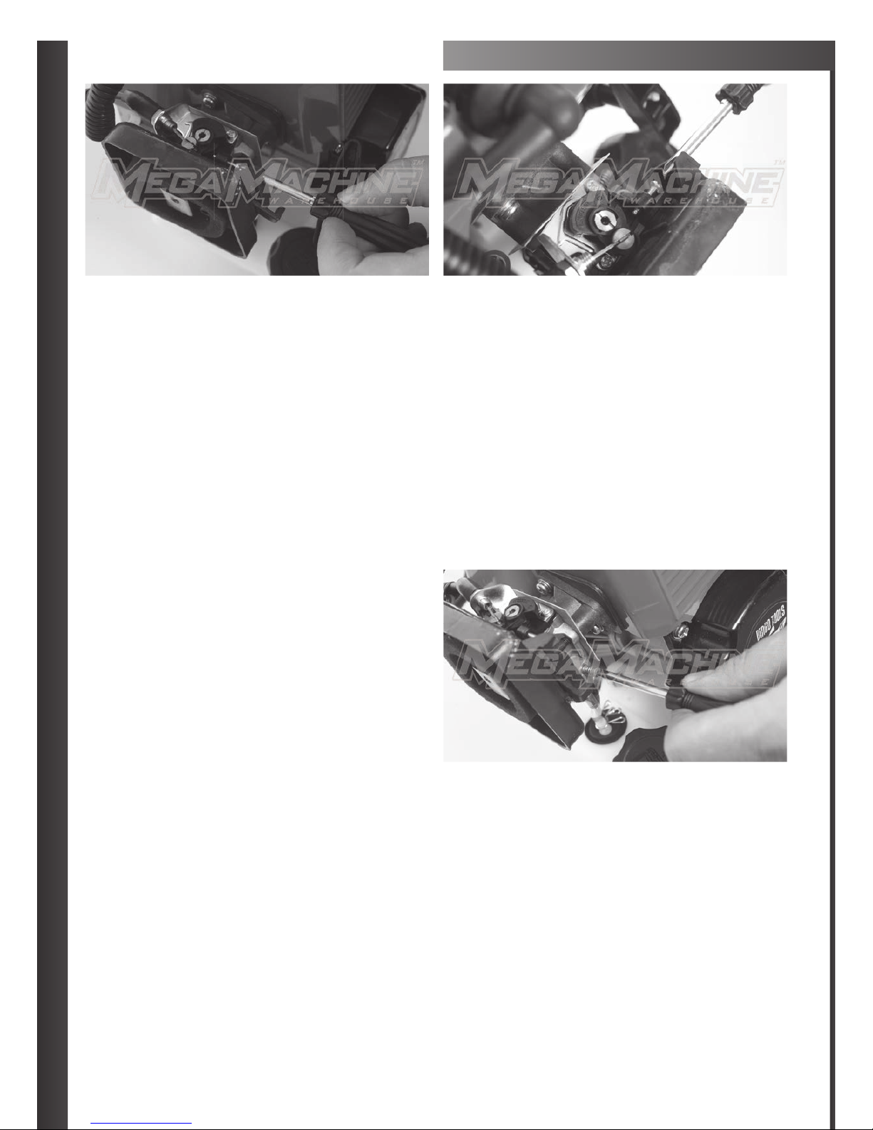
When looking down in a birds eye view at the carby or Choke area, at the the top of the Carby where the throttle control cable
attaches to the side of the mechanism, you will see a silver screw on the right hand side at the top.
Where the Sliver Screw enters in and the tip of the Silver Screw comes out the outer side, you should be able to view when looking
at least 3 – 4mm of screw tip, turning this screw to the left will speed up the idle, while turning the silver screw to the right will slow
the idle down.
We suggest that you adjust the screw so you may be able to view 3 or 4mm of screw tip, if you see more screw tip, please back
adjust the screw to this suggested setting and if you are viewing less of the screw tip, please adjust the screw so you are able to
view more of the tip at least 3 or 4mm of screw tip and no more or less.
FUEL MIXTURE SCREW ADJUSTMENT
If your machine is not revving or not running correctly
please adjust the Fuel Mixture Screw with the steps
to the right.
When facing the Carby side of the machine and looking at
the carby on the right hand side of the Carby down near the
top of the fuel tank and infront of the black fuel line in take
tube, you will see a brass screw, this is the fuel mix screw,
this adjusts how much fuel may enter the machine.
To set this screw in the correct position we need to start the screw at zero first, please turn the brass screw all the way to the right
or clock wise until it will not turn any further, please try not to over turn it when screwing it all the way in, as when you have reached
the end of it’s thread and if you keep turning it with force, you may snap the screw off.
When you have turned the screw all the way in to the right or clock wise so it can not turn any further this is what we call or state
as being at zero. Now please turn the screw 1 and 1 quarter turns to the left or anticlock wise to set it in the correct position for the
fuel intake and smooth operation.
*** NOTE ***
If 1 and 1 quarter turns isnt enough as the adjustment has not being successful please start the brass screw back at zero and try
a 1 and half full turns anti clock wise or to the left to set the carby with a little bit more fuel into the machine.

11
CUTTING OPERATION
»Always Cut by Guiding the head from your right to left.
» Adjust the idle speed (see page X) for different types of grass you cut e.g cut tough shrubs or weeds at a high idle, and young
grass at a middle speed.
» A metal blade cut best up to the point 1/3 from the edge. Use that area for cutting shrubs, tough and thick weeds. For cutting
young grass, you can use up to 2/3 from the tip of the blade.
MAINTENANCE OF MACHINE
Gear Case
» Please Supply Multi-purpose grease at every 25 hours of use. Remove the cutter holders to arrange for old grease to exsist.
Maitenance Before Storage
» Brushing off dirt from the machine, check damage or slack of each part. If you find out abnormalities,
repair them for the next use.
» Extract fuel from the tank, and loose the drain screw of the float cabin to extract fuel, turn on the engine, and leave it running
until it stops naturally.
» Remove the spark plug and put in 1-2cc of 2 cycle oil in the engine. Draw the starter 2-3 times, set the plug back and stop it at
the contaction position.
» Apply anti-rust oil to the metal parts such as the throttle wire, put the cover on the blade, and keep it indoor avoiding dampness.
PLEASE BE AWARE THAT THE CUTTING ATTACHMENTS CAN CONTINUE ROTATING AFTER THE ENGINE IS
SWITCHED OFF! SO PLEASE WATCH OUT FOR THIS. WE RECOMMEND USING 20:1 UNLEADED FUEL TO OIL
MIXTURE FOR THIS BRUSHCUTTER.
Other manuals for 52CC
2
Table of contents