DINUY CO K5X 002 Specification sheet

Page 1/4
Operation and installation manual
CO K5X 002 –KNX RF/TP Coupler
Application
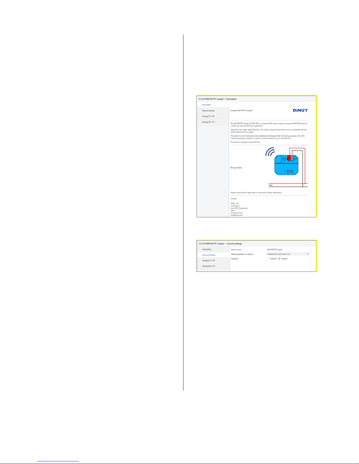
The KNX RF/TP Coupler is a compact KNX radio coupler. It
connects KNX RF devices of a radio line with the KNX Bus
Twisted Pair.
The device has a filter table for group addresses. The coupler
supports long frames and is compatible with the ETS® software
ETS5 or higher.
The buttons on the front panel allow disabling the telegram filter
for testing purposes. The LEDs indicate operating conditions as
well as communication errors on the KNX bus.
The power is supplied via the KNX bus.
Coupler function
KNX RF/TP Coupler as line coupler
The individual address assigned to the KNX RF/TP Coupler in
the form of x.y.0 (x, y: 1..15) sets up, that the device operates as
a line coupler.
The KNX RF/TP Coupler has a filter table and thus contributes to
reducing the bus load. The filter table supports the extended
group address range (main group 0..31) and is automatically
generated by the ETS.
Installation and Connection
The device can be flush-mounted, the housing fits into a stan-
dard flush-mounted box.
When choosing the installation location the range of RF devices
to be associated with the gateway has to be considered. Shield-
ing objects (e.g. metal cabinets) or interfering transmitters (e.g.
computers, electronic transformers, ballasts) near the gateway
should be avoided.
The connection to the KNX bus is made with a bus connector.
The correct polarity of the terminal referred to the printing inside
the unit has to be considered.
The KNX RF/TP Coupler features the following controls and
displays:
An external power supply is not necessary as the device is
powered by the KNX bus.
The device is not working without bus power.
KNX Programming mode
The KNX programming mode is activated/deactivated by press-
ing the KNX programming button ❶. When the programming
mode is active, the programming LED ❷lights red.
A gateway ex-factory has the default individual address 15.15.0.
Manual operation and status display
The State LED ❹lights up if the device is successfully powered
by the KNX bus. This LED blinks red, when the application is not
running, e.g. after a failed ETS download. The State LED ❹
lights up orange to indicate that manual operation is active.
The LEDs 1-4 ❺ show TP traffic.
The LEDs 5-8 ❺ show RF traffic.
Manual operation TP
Pressing button A ❻short, enters the manual operation for TP
mode.
By pressing button A ❻, routing runtime telegrams (group
telegrams) will be enabled/disabled. This will be indicated by
LEDs 1 and 2 ❺.
By pressing button B ❼, routing management telegrams (indi-
vidual addressed and broadcast telegrams) will be
enabled/disabled. This will be indicated by LEDs 3 and 4 ❺.
EN
❶Button P KNX Prog
❷LED P KNX Prog
❸KNX bus connector
❹LED S State
❺LEDs 1-8
❻Button A
❼Button B
Page 2/4
Press button A ❻ or button B ❼ long to exit the manual opera-
tion mode.
Manual operation RF
Pressing button B ❼short, enters the manual operation for RF
mode.
By pressing button A ❻, routing runtime telegrams (group
telegrams) will be enabled/disabled. This will be indicated by
LEDs 5 and 6 ❺.
By pressing button B ❼, routing management telegrams (indi-
vidual addressed, broadcast and system broadcast telegrams)
will be enabled/disabled. This will be indicated by LEDs 7 and 8
❺.
Press button A ❻ or button B ❼ long to exit the manual opera-
tion mode.
Factory default settings
The following configuration is set by factory default:
Individual device address: 15.15.0
Routing (TP line RF line):
Individual addressed telegrams: Filter
Group addressed telegrams: Block
Routing (RF line TP line):
Individual addressed telegrams: Filter
Group addressed telegrams: Block
Reset to factory device settings
It is possible to reset the device to its factory settings:
Disconnect the KNX Bus connector ❸from device
Press the KNX programming button ❶and keep it
pressed down
Reconnect the KNX Bus connector ❸of device
Keep the KNX programming button ❶pressed for at
least another 6 seconds
A short flashing of the all LEDs ❷, ❹and ❺visualizes
the successful reset of the device to factory default set-
tings.
ETS database
The ETS database (for ETS 5) can be downloaded from the
product website of the KNX RF/TP Coupler: www.dinuy.com.
ETS parameter dialogue
The following parameters can be set using the ETS.
Description
The first page shows general information about the device.
General settings
Device name (30 Characters)
An arbitrary name can be assigned for the KNX RF/TP Coupler.
The device name should be meaningful, e.g. “Living Room”.
Manual operation on device
This parameter sets the duration of the manual mode. Upon
completion the normal display mode is restored.
Repeater
Disabled: Received telegrams will not be repeated.
Enabled: Received telegrams will be repeated to
extend the RF range.
The KNX RF/TP Coupler can also be used as a repeater. In this
case, the individual address has the form x.y.z, where z must not
be equal to 0. The filter settings in the parameter dialog of the
ETS are ineffective in repeater mode.
Page 3/4
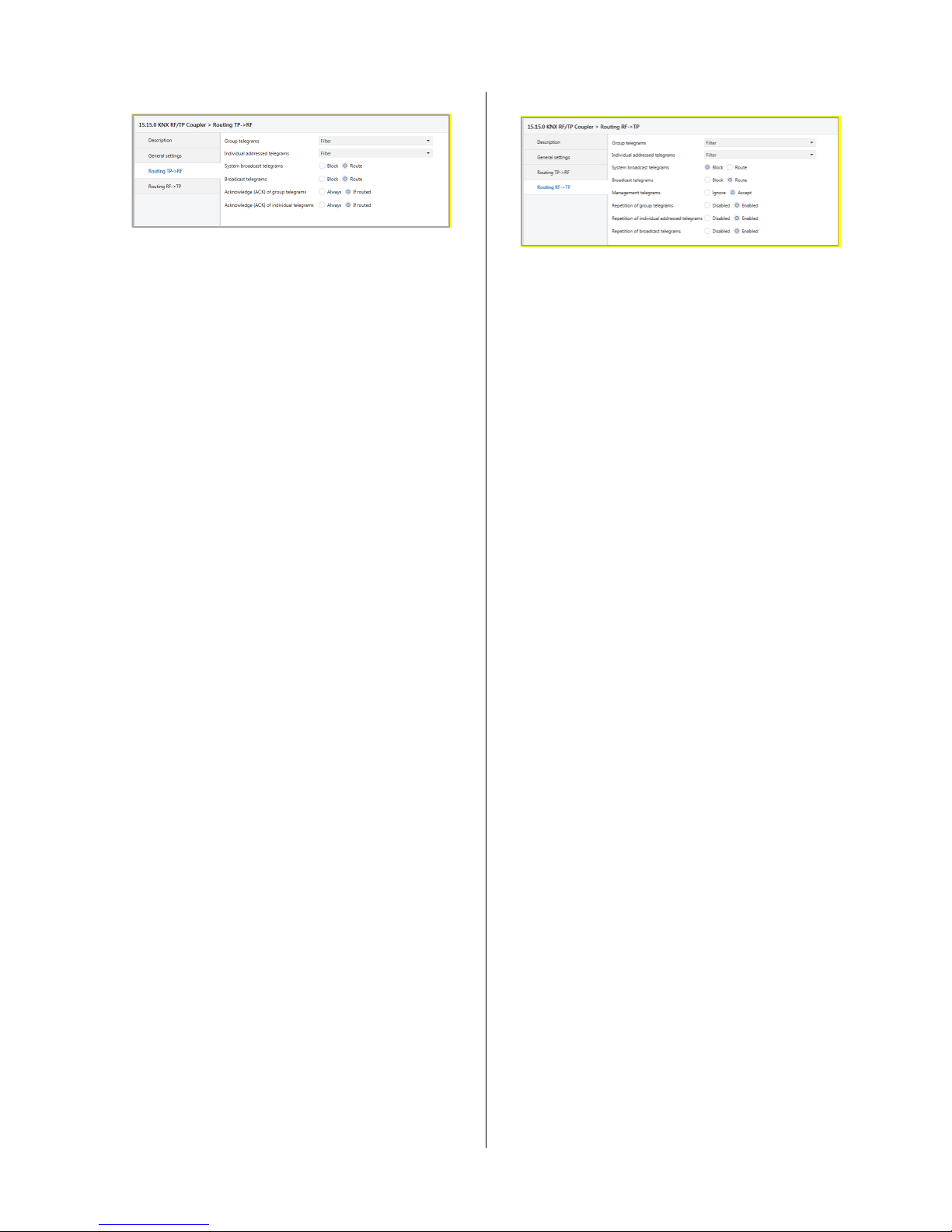
Routing (TP line RF line)
Group telegrams
Block: No group telegrams are routed to the RF
line.
Route: All group telegrams are routed to the RF line
independent of the filter table. This setting is
for test purposes only.
Filter: The filter table is used to check whether or
not the received group telegram should be
routed to the RF line.
Individual addressed telegrams
Block: No individually addressed telegrams are
routed to the RF line.
Route: All individually addressed telegrams are
routed to the RF line. This setting is for test
purposes only.
Filter: The individual address is used to check
whether the received individually addressed
telegram should be routed to the RF line.
System broadcast telegrams
Block: No received system broadcast telegrams are
routed to the RF line.
Route: All received system broadcast telegrams are
routed to the RF line.
Broadcast telegrams
Block: No received broadcast telegrams are routed
to the RF line.
Route: All received broadcast telegrams are routed
to the RF line.
Acknowledge (ACK) of group telegrams
Always: A acknowledge is generated for every re-
ceived group telegram (from the TP line).
Only if routed: A acknowledge is only generated for re-
ceived group telegrams (from the TP line) if
they are routed to the RF line.
Acknowledge (ACK) of individual telegrams
Always: A acknowledge is generated for every re-
ceived individual addressed telegram (from
the TP line).
Only if routed: A acknowledge is only generated for re-
ceived individually addressed group tele-
grams (from the TP line) if they are routed to
the RF line.
Routing (RF line TP line)
Group telegrams
Block: No group telegrams are routed to the TP
line.
Route: All group telegrams are routed to the TP line
independent of the filter table. This setting is
for test purposes only.
Filter: The filter table is used to check whether or
not the received group telegram should be
routed to the TP line.
Individually addressed telegrams
Block: No individually addressed telegrams are
routed to the TP line.
Route: All individually addressed telegrams are
routed to the TP line. This setting is for test
purposes only.
Filter: The individual address is used to check
whether the received individually addressed
telegram should be routed to the TP line.
System broadcast telegrams
Block: No received system broadcast telegrams are
routed to the TP line.
Route: All received system broadcast telegrams are
routed to the TP line.
Broadcast telegrams
Block: No received broadcast telegrams are routed
to the TP line.
Route: All received broadcast telegrams are routed
to the TP line.
Management telegrams
Ignore: The received management telegram from
the RF line will be ignored.
Accept: The received management telegram from
the RF line will be accepted.
Repetition of group telegrams
Disabled: The received group telegram is not resent to
the TP line in case of a fault.
Enabled: The received group telegram is resent up to
three times in case of a fault.
Repetition of individual addressed telegrams
Disabled: The received individually addressed tele-
gram is not resent to the TP line in case of a
fault.
Enabled: The received individually addressed tele-
gram is resent up to three times in case of a
fault.
Page 4/4
Repetition of broadcast telegrams
Disabled: The received broadcast telegram is not
resent to the TP line in case of a fault.
Enabled: The received broadcast telegram is resent
up to three times in case of a fault.
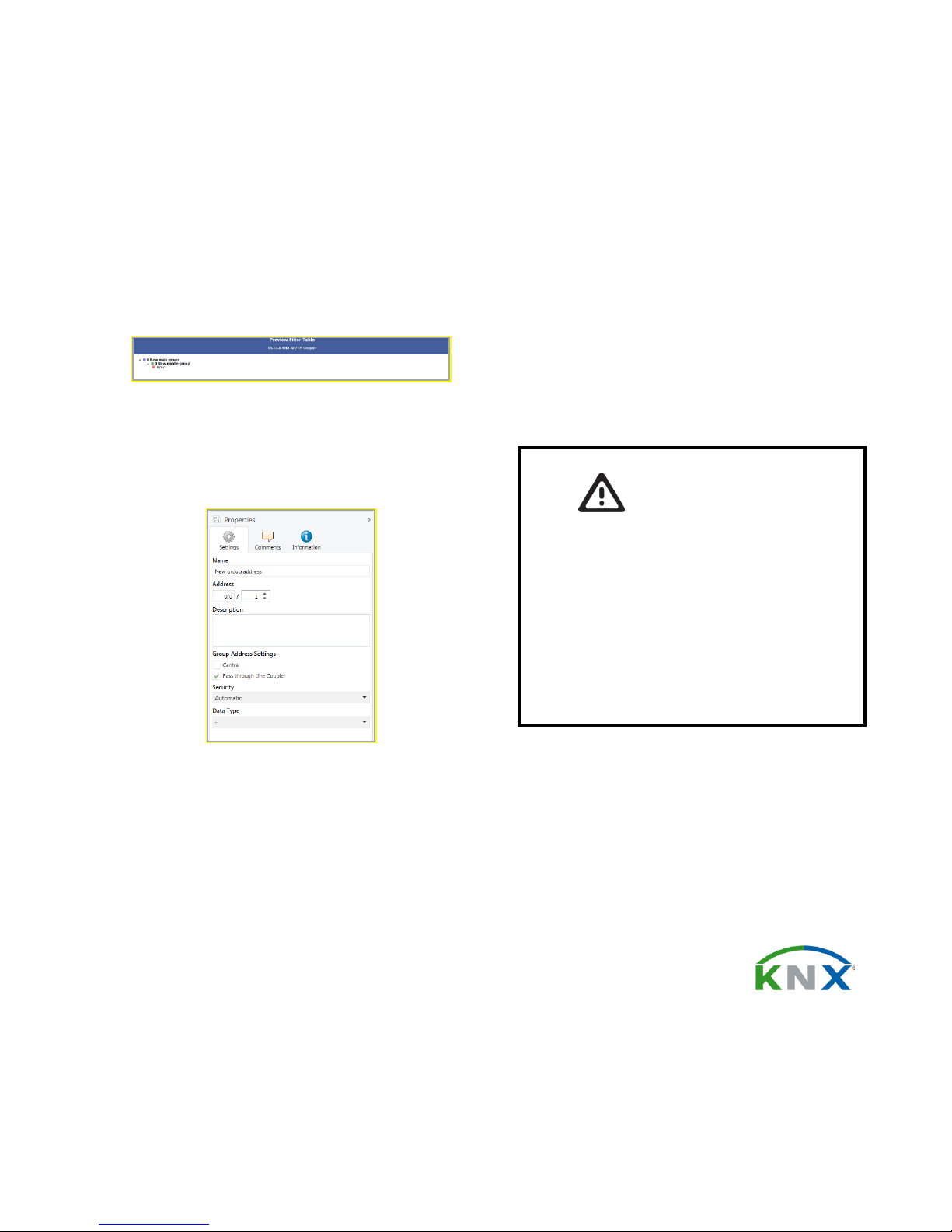
Filter table
The filter table is automatically created by the ETS. The group
addresses of the telegrams which shall be forwarded via the
coupler are added to the filter table. The contents of the filter
table can be displayed via the preview:
Preview of the filter table
The filter table can be extended by manually adding group ad-
dresses. This requires activating "Pass through Line Coupler" in
the property window of the corresponding group address.
Property window of a group address
DINUY S.A.
C/Auzolan 2, 20303 Irún (Spain)
http://www.dinuy.com
knx@dinuy.com
WARNING
The device must be mounted and commis-
sioned by an authorized electrician.
The prevailing safety rules must be heeded.
The device must not be opened.
For planning and construction of electric in-
stallations, the relevant guidelines, regulations
and standards of the respective country are to
be considered.


