CHAPTER II
INSTALLATION
2-1. UNPACKING.
Carefully remove the unit from the shipping carton
and examine it for evidence of damage. If any
damage is discovered, immediately notify the trans-
portation company that delivered the unit. Be sure
to keep the shipping carton and packing material as
the transportation company will want to examine
them if there is a damage claim. Keep the carton
and packing material even if no shipping damage
occurs. Having the original carton available makes
packing the unit much easier if it should ever be
necessary to store it or return it to the factory for
service.
NOTE
Fill out the enclosed registration card
and return it to the factory immediately
to insure registration and validation of
the warranty.
2-2. LOCATION.
The location of the TR-4C is not critical. However,
care should be taken to insure that adequate clear-
ance is provided to insure free circulation of air
around the unit and to allow access to the side
controls and connectors. Do not cover the top of
the cabinet with books, papers or other equipment
as overheating may result.
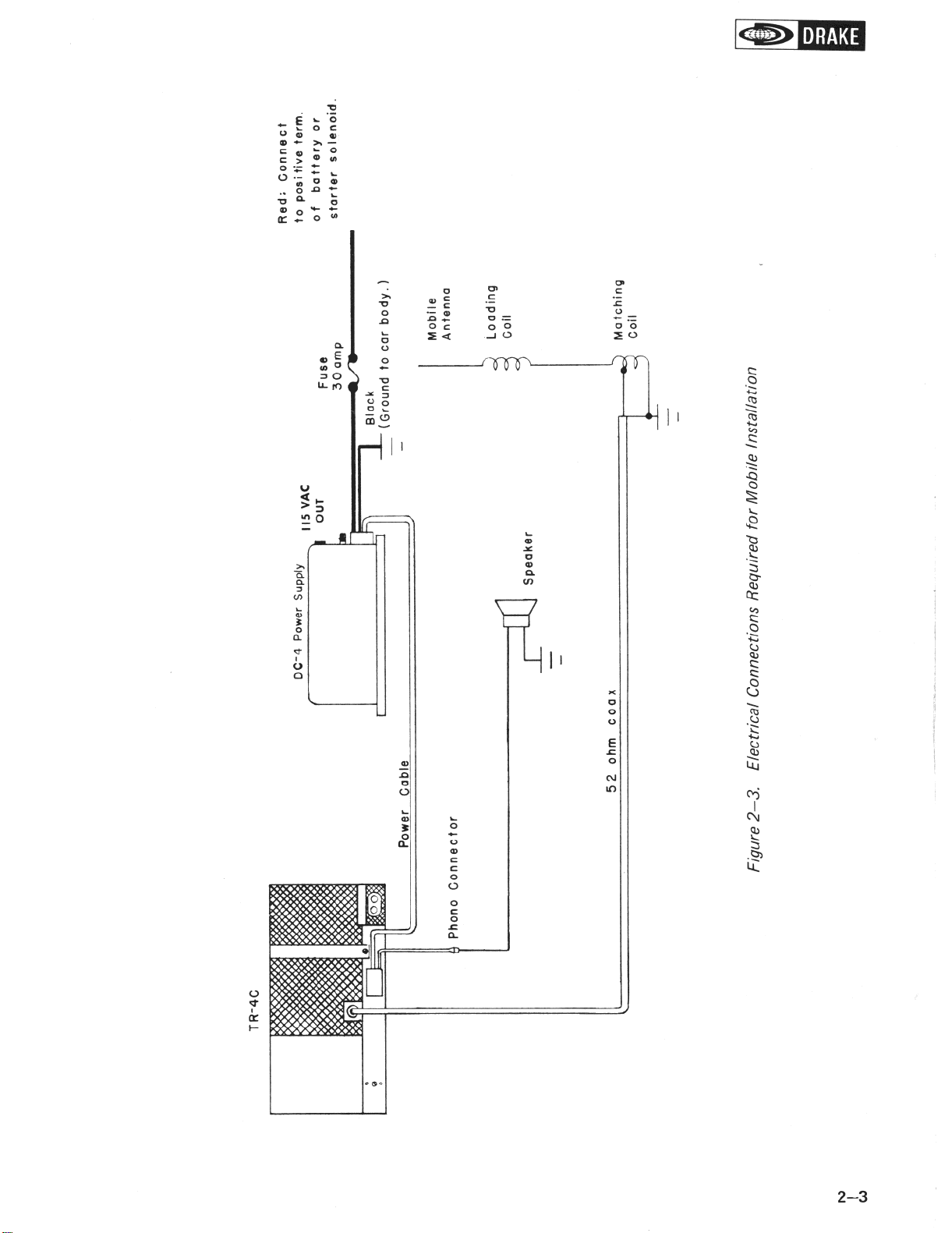
2-3. MOBILE INSTALLATION.
2-4. POWER REQUIREMENTS. Refer to figure
2-2 for rear chassis connector identification. The
TR-4C
may be installed in any vehicle with a 12
volt dc negative ground system. An R. L. Drake
Model DC-4 Power Supply is required for a mobile
installation. The recommended location for the
DC-4 is on the passenger side of the firewall. Refer
to figure 2-3 for the electrical connections required.
2-5. MOUNTING. Mount the TR-4C in a con-
venient location below the dash with an R. L. Drake
Model MMK-3 Mobile Mounting Kit. Refer to
figure 2-4 for various mounting options. Be sure
to allow adequate clearance for air circulation and
cable connections. Turn the TR-4C off. Connect
the power cable between the TR-4C and the DC-4.
Coil up any excess cable and tape it in place out of
sight. Connect the black wire from the power supply
to a convenient ground. Route the red wire from the
power supply through the firewall and connect it to
the positive battery terminal or the starter solenoid.
The fuse holder should be installed as close to the
solenoid as possible. Shorten both of these wires as
much as possible.
2-6. ANTENNA. Install a mobile antenna as rec-
ommended by the antenna manufacturer. Connect
a coaxial cable from the antenna to the SO-239
connector at the rear of the TR-4C.
2-7. SPEAKER. DO NOT connect the TR-4C to
the speaker of the car radio. Install a separate
speaker for use with the TR-4C. The R. L. Drake
Model MC-4 Mobile Console is recommended for
this type of installation. It includes a speaker and a
wattmeter and is designed to mount over or under
the TR-4C.
2-8. MICROPHONE. Use a microphone with a flat
frequency response. The microphone should have a
cardioid pattern to reduce pickup from the back
and sides. Connect the microphone as illustrated in
figure 2-l to insure proper performance.
L-_________~
S-230 CONNECTOR
MICROPHONE
Figure
2-
1.
Microphone Connections
2-l