DIY REPLICA Series User manual

do it
yourself,
it’s better!
Manuale d’assemblaggio
Assembly manual
KIT “The Buer”
REPLICA Series
REPLICA
OUT IN
100%
Satised

Necessario all’assemblaggio (non incluso nel kit)
Elenco degli strumenti necessari all’assemblaggio (non inclusi nel KIT): saldatore e stagno per saldatu-
re, forbici e pinze, cacciavite a stella, alimentatore 9V stabilizzato per pedali eetto e tester (consigliato
per il debugging ma non strettamente necessario).
Disclaimer: Le informazioni contenute in questo documento non impegnano la responsabilità di DIY
Pedal Gear Parts. DIY Pedal Gear Parts non assume alcuna responsabilità per quanto riguarda il materia-
le contenuto in questo documento ed eventuali danni a persone o cose causati dalla sua scorretta inter-
pretazione ed utilizzo.
Copyright: Il presente documento(immagini e testo) è di proprietà di DIY Pedal Gear Parts ed è vietata
la sua riproduzione parziale o totale senza previa autorizzazione.
Necessary for the assembly and not include in the KIT
The following tools, necessary to assembly the eect pedal, are not included in the KIT: soldering-iron
and solder, screwdriver, 9V stabilized power supply and tester (useful for debugging but not extremely
necessary).
Disclaimer: DIY Pedal Gear Parts is not responsible in any form for the information provided in this
document. DIY Pedal Gear Parts is not suitable for the information described in this document or for
damages caused by wrong interpretation and misuse of the techniques described in this tutorial.
Copyright: This document (text and images) is property of DIY Pedal Gear Parts: it is not allowed to
reproduce the content of this document in any form without being authorized by DIY Pedal Gear Parts.
Parte/Part Valore/ Value
Condensatori/Capacitors
C14 100nF (Polyester-Mylar green)
C15 4.7uF (Electrolytic)
C16 1nF (Polyester-Mylar green)
C17 22uF (Electrolytic)
C18 220uF (Electrolytic)
Resistenze/Resistors
R17 10M
R18 1K
R19 120K
R20 120K
R21 200K
R22 8.2K
R23 20K
R24 150R
R25 51K
R27 100R
RLED 2.2K
Diodi/Diodes
D4 1N4007
D5 1N4007
Transistor
T1 BC549C
PC1: Circuito/PCB
E1: Scatola in alluminio/Aluminum enclosure 1590B
S1: Adesivo/Top sticker
SW1: Interruttore/Footswitch 3pdt
DC1: Jack alimentazione/DC power jack
J1: Jack input
J2: Jack output
L1: LED
L2: Porta LED/LED bezel
W1: Filo per collegamenti/wire
REPLICA

6.Preparazione della scatola/Enclosure preparation
E’ necessario forare il box in alluminio secondo le indicazioni
dell’adesivo fornito nel KIT (per la parte superiore). Si può proce-
dere applicando l’adesivo sul box pulito e con l’aiuto di un trapa-
no si possono praticare i fori come da posizioni/sezioni prede-
terminate. Per i fori laterali (jack input/output, alimentazione)
procedere stampando il layout di foratura fornito nella sezione 8
ed applicandolo sul box con del nastro adesivo. Una volta che
combaciano i fori della parte superiore procedere a segnare i fori
laterali e a forare il box con l’aiuto del trapano.
It is necessary to prepare the aluminum enclosure with the
related holes as indicated in the sticker included in the KIT for
the top plate. You can apply the sticker on the top face of the box
and by the help of a driller you can proceed with making the
necessary holes. For the lateral holes related (jack input/output
and power dc jack) please proceed by printing the drilling
template provided in section 8 and by applying it on the box by
means of tape when needed. Once the holes of the box (realized
on the base of the sticker) and the holes of the printed drilling
template coincide on the top plate, the lateral holes can be
made by the help of a driller.
7. Assemblaggio della scatola/
Assembly of the enclosure
Assembare il box con i componenti elettromeccanici necessari:
jack input/output, LED di stato e porta LED, interruttore 3PDT,
interruttore a levetta (se applicabile), jack di alimentazione e
connettore batteria 9V (opzionale/se applicabile). PS: Per
semplicità si consiglia di procedere all’assemblaggio del jack di
alimentazione e successivamente del toggle switch.
Proceed with assembling all electro-mechanical components
with the aluminum enclosure: jack input/output, status led and
led bezel, 3PDT footswitch, toggle switch (if applicable), DC
power jack and 9V battery snap (optional/if applicable). For
simplicity it is advisable to assemble rst the DC power jack and
then the toggle switch.
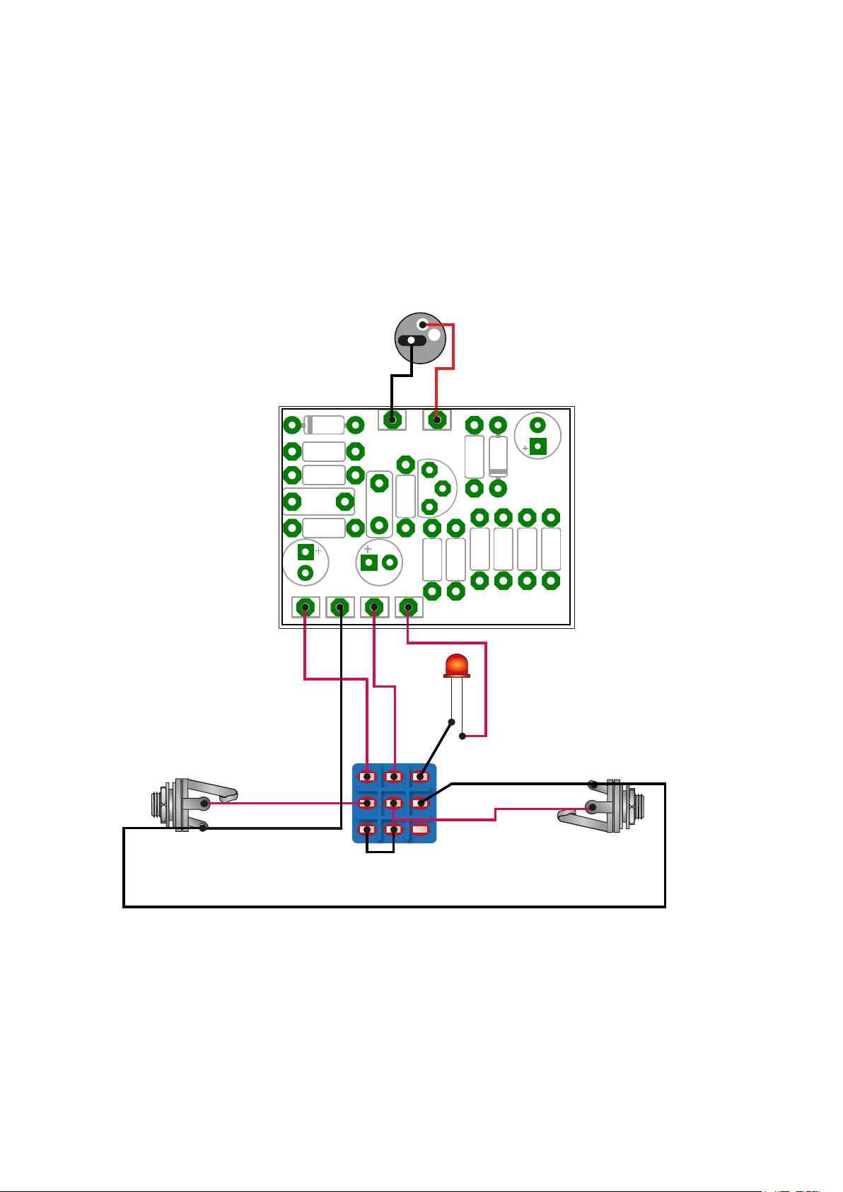
8. Cablaggio PCB/PCB Wiring
Inziare con il cablaggio del LED di stato e della terra (GND)
secondo lo schema di montaggio fornito nella sezione 5. Proce-
dere poi con tutti gli altri componenti: potenziometri, jack
input/output, LED di stato e porta LED, interruttore 3PDT, inter-
ruttore a levetta (se applicabile), jack di alimentazione e connet-
tore batteria 9V (opzionale/se applicabile).
.We can start by wiring the status LED and the grounding (GND)
on the base of the mounting schematic provided in section 5.
We can then proceed with all other components: potentiome-
ters, jack input/output, status led and Led bezel, 3PDT footswi-
tch, toggle switch (if applicable), DC power jack and 9V
battery
snap (optional/if applicable).
9. Test sonoro/Assembly test
Ottimo lavoro! Se tutti gli step descritti precedentemente sono
stati eseguiti correttamente, potete ora sigillare la parte poste-
riore della scatola, alimentare il pedale e fare un test sonoro. NB:
Utilizzare solamente alimentatori stabilizati e certicati.
Good job! If all previously described steps have been successful-
ly accomplished, you can now close the back plate of the enclo-
sure and you can make a sound test of your DIY pedal eect. NB:
Use only stabilyzed and certied power supply.
10. Risoluzione problemi/Trouble shooting
Nel caso di malfunzionamento del pedale assemblato far riferi-
mento alla sezione 9 per la risoluzione dei problemi.
In case of a malfunctioning pedal eect, you can follow our
tutorial on troubleshooting to solve the issues (see section 9).
Scatola/Box 1590B
E1
Circuito/PCB
PC1
Adesivo/Top sticker
S1
Interruttore/
Footswitch 3pdt
Resistenze /
Resistors 1/4W
Diodi/Diodes
Condensatori/
Capacitors
Jack alimentazione/
DC power jack
Jack input
Jack output
SW1
R17/RLED
L1-L2
J1-J2
DC1
T1
D4/D5
C14-C18
Transistors
Led e portaled/
Led and led bezel
Filo per collegamenti/Wire
W1
R R R R
+
-
+ -
OUT IN
3
+
6.Preparazione della scatola/Enclosure preparation
E’ necessario forare il box in alluminio secondo le indicazioni
dell’adesivo fornito nel KIT (per la parte superiore). Si può proce-
dere applicando l’adesivo sul box pulito e con l’aiuto di un trapa-
no si possono praticare i fori come da posizioni/sezioni prede-
terminate. Per i fori laterali (jack input/output, alimentazione)
procedere stampando il layout di foratura fornito nella sezione 8
ed applicandolo sul box con del nastro adesivo. Una volta che
combaciano i fori della parte superiore procedere a segnare i fori
laterali e a forare il box con l’aiuto del trapano.
It is necessary to prepare the aluminum enclosure with the
related holes as indicated in the sticker included in the KIT for
the top plate. You can apply the sticker on the top face of the box
and by the help of a driller you can proceed with making the
necessary holes. For the lateral holes related (jack input/output
and power dc jack) please proceed by printing the drilling
template provided in section 8 and by applying it on the box by
means of tape when needed. Once the holes of the box (realized
on the base of the sticker) and the holes of the printed drilling
template coincide on the top plate, the lateral holes can be
made by the help of a driller.
7. Assemblaggio della scatola/
Assembly of the enclosure
Assembare il box con i componenti elettromeccanici necessari:
jack input/output, LED di stato e porta LED, interruttore 3PDT,
interruttore a levetta (se applicabile), jack di alimentazione e
connettore batteria 9V (opzionale/se applicabile). PS: Per
semplicità si consiglia di procedere all’assemblaggio del jack di
alimentazione e successivamente del toggle switch.
Proceed with assembling all electro-mechanical components
with the aluminum enclosure: jack input/output, status led and
led bezel, 3PDT footswitch, toggle switch (if applicable), DC
power jack and 9V battery snap (optional/if applicable). For
simplicity it is advisable to assemble rst the DC power jack and
then the toggle switch.
8. Cablaggio PCB/PCB Wiring
Inziare con il cablaggio del LED di stato e della terra (GND)
secondo lo schema di montaggio fornito nella sezione 5. Proce-
dere poi con tutti gli altri componenti: potenziometri, jack
input/output, LED di stato e porta LED, interruttore 3PDT, inter-
ruttore a levetta (se applicabile), jack di alimentazione e connet-
tore batteria 9V (opzionale/se applicabile).
.We can start by wiring the status LED and the grounding (GND)
on the base of the mounting schematic provided in section 5.
We can then proceed with all other components: potentiome-
ters, jack input/output, status led and Led bezel, 3PDT footswi-
tch, toggle switch (if applicable), DC power jack and 9V
battery
snap (optional/if applicable).
4 - ASSEMBLAGGIO PASSO-PASSO/ STEP-BY-STEP ASSEMBLY INSTRUCTIONS
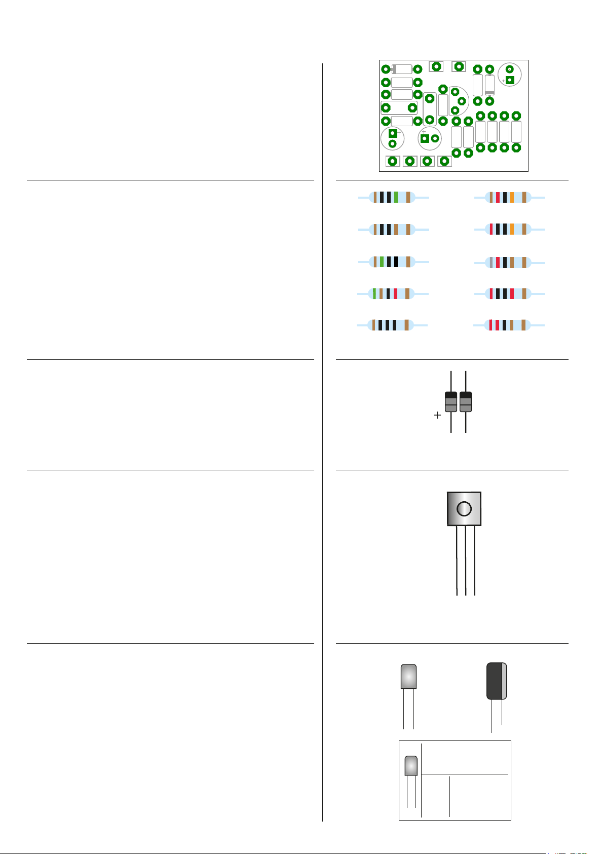
R17 10M
T1
Silicon
BC549C
C
B
E
POLYESTER-MYLAR
CODICI CONDENSATORI/
CAPACITOR CODES:
POLYESTER-MYLAR
2A104J 100nF
2A102J 1nF
ELECTROLYTIC
R18 1K
R19/R20 120K
+ -
9. Test sonoro/Assembly test
Ottimo lavoro! Se tutti gli step descritti precedentemente sono
stati eseguiti correttamente, potete ora sigillare la parte poste-
riore della scatola, alimentare il pedale e fare un test sonoro. NB:
Utilizzare solamente alimentatori stabilizati e certicati.
Good job! If all previously described steps have been successful-
ly accomplished, you can now close the back plate of the enclo-
sure and you can make a sound test of your DIY pedal eect. NB:
Use only stabilyzed and certied power supply.
10. Risoluzione problemi/Trouble shooting
Nel caso di malfunzionamento del pedale assemblato far riferi-
mento alla sezione 9 per la risoluzione dei problemi.
In case of a malfunctioning pedal eect, you can follow our
tutorial on troubleshooting to solve the issues (see section 9).
1.Controllo componenti/Components check
Controllare che i componenti inclusi nella scatola del kit
risultano essere gli stessi elencati nella lista della sezione 1.
Please, check that all provided components comply to the
parts list provided in section 1.
2.Resistenze/Resistors
Assemblare/saldare i componenti sulla PCB a partire dalle
resistenze (la combinazione valore resistenza/colori è
disponibile a lato). Nel corso di questo passaggio, si posso-
no anche montare i trimpot/trimmer se presenti nel circui-
to.
Let’s start the assembly/soldiering work with the resistors
(the combination value/colored bands is available on the
right side). During this step, also the trimpot/trimmer can
be mounted, if available in the circuit.
3.Diodi/Diodes
Procedere con l’assemblaggio/saldatura dei diodi sulla PCB.
Proceed with assembly/soldiering of the diodes on the PCB.
4. IC/transistor
Assemblare il circuito integrato sulla PCB iniziando con la
saldatura del socket procedendo poi con il montaggio
dell’IC e dei transistor. Qualora il pedale che si sta assem-
blando non preveda IC oppure transistor saltare questo
passo.
It’s time to mount on the PCB the IC, starting by soldering
the IC socket and proceeding with transistors. If the eect
pedal you are mounting does not include the IC and/or the
transistors you can skip this step.
5.Condensatori/Capacitors
Procedere successivamente con il montaggio dei conden-
satori: prima quelli non polarizzati e poi quelli polarizzati
(elettrolitici). Per i condensatori polarizzati si consiglia di
fare attenzione alla polarità (verso di montaggio).
We can proceed with mounting the capacitors on the PCB:
rst the non-polarized ones and then the polarized caps
(electrolytic). Please, pay attention to the polarity of the
polarized capacitors.
D4/D5
R24 150Ohm
R21 200K
R22 8.2K
R23 20KR25 51K
R23 2.2KR26 100Ohm
+

6.Preparazione della scatola/Enclosure preparation
E’ necessario forare il box in alluminio secondo le indicazioni
dell’adesivo fornito nel KIT (per la parte superiore). Si può proce-
dere applicando l’adesivo sul box pulito e con l’aiuto di un trapa-
no si possono praticare i fori come da posizioni/sezioni prede-
terminate. Per i fori laterali (jack input/output, alimentazione)
procedere stampando il layout di foratura fornito nella sezione 8
ed applicandolo sul box con del nastro adesivo. Una volta che
combaciano i fori della parte superiore procedere a segnare i fori
laterali e a forare il box con l’aiuto del trapano.
It is necessary to prepare the aluminum enclosure with the
related holes as indicated in the sticker included in the KIT for
the top plate. You can apply the sticker on the top face of the box
and by the help of a driller you can proceed with making the
necessary holes. For the lateral holes related (jack input/output
and power dc jack) please proceed by printing the drilling
template provided in section 8 and by applying it on the box by
means of tape when needed. Once the holes of the box (realized
on the base of the sticker) and the holes of the printed drilling
template coincide on the top plate, the lateral holes can be
made by the help of a driller.
7. Assemblaggio della scatola/
Assembly of the enclosure
Assembare il box con i componenti elettromeccanici necessari:
jack input/output, LED di stato e porta LED, interruttore 3PDT,
interruttore a levetta (se applicabile), jack di alimentazione e
connettore batteria 9V (opzionale/se applicabile). PS: Per
semplicità si consiglia di procedere all’assemblaggio del jack di
alimentazione e successivamente del toggle switch.
Proceed with assembling all electro-mechanical components
with the aluminum enclosure: jack input/output, status led and
led bezel, 3PDT footswitch, toggle switch (if applicable), DC
power jack and 9V battery snap (optional/if applicable). For
simplicity it is advisable to assemble rst the DC power jack and
then the toggle switch.
8. Cablaggio PCB/PCB Wiring
Inziare con il cablaggio del LED di stato e della terra (GND)
secondo lo schema di montaggio fornito nella sezione 5. Proce-
dere poi con tutti gli altri componenti: potenziometri, jack
input/output, LED di stato e porta LED, interruttore 3PDT, inter-
ruttore a levetta (se applicabile), jack di alimentazione e connet-
tore batteria 9V (opzionale/se applicabile).
.We can start by wiring the status LED and the grounding (GND)
on the base of the mounting schematic provided in section 5.
We can then proceed with all other components: potentiome-
ters, jack input/output, status led and Led bezel, 3PDT footswi-
tch, toggle switch (if applicable), DC power jack and 9V
battery
snap (optional/if applicable).
9. Test sonoro/Assembly test
Ottimo lavoro! Se tutti gli step descritti precedentemente sono
stati eseguiti correttamente, potete ora sigillare la parte poste-
riore della scatola, alimentare il pedale e fare un test sonoro. NB:
Utilizzare solamente alimentatori stabilizati e certicati.
Good job! If all previously described steps have been successful-
ly accomplished, you can now close the back plate of the enclo-
sure and you can make a sound test of your DIY pedal eect. NB:
Use only stabilyzed and certied power supply.
10. Risoluzione problemi/Trouble shooting
Nel caso di malfunzionamento del pedale assemblato far riferi-
mento alla sezione 9 per la risoluzione dei problemi.
In case of a malfunctioning pedal eect, you can follow our
tutorial on troubleshooting to solve the issues (see section 9).
?
OUT IN
6.Preparazione della scatola/Enclosure preparation
E’ necessario forare il box in alluminio secondo le indicazioni
dell’adesivo fornito nel KIT (per la parte superiore). Si può proce-
dere applicando l’adesivo sul box pulito e con l’aiuto di un trapa-
no si possono praticare i fori come da posizioni/sezioni prede-
terminate. Per i fori laterali (jack input/output, alimentazione)
procedere stampando il layout di foratura fornito nella sezione 8
ed applicandolo sul box con del nastro adesivo. Una volta che
combaciano i fori della parte superiore procedere a segnare i fori
laterali e a forare il box con l’aiuto del trapano.
It is necessary to prepare the aluminum enclosure with the
related holes as indicated in the sticker included in the KIT for
the top plate. You can apply the sticker on the top face of the box
and by the help of a driller you can proceed with making the
necessary holes. For the lateral holes related (jack input/output
and power dc jack) please proceed by printing the drilling
template provided in section 8 and by applying it on the box by
means of tape when needed. Once the holes of the box (realized
on the base of the sticker) and the holes of the printed drilling
template coincide on the top plate, the lateral holes can be
made by the help of a driller.
7. Assemblaggio della scatola/
Assembly of the enclosure
Assembare il box con i componenti elettromeccanici necessari:
jack input/output, LED di stato e porta LED, interruttore 3PDT,
interruttore a levetta (se applicabile), jack di alimentazione e
connettore batteria 9V (opzionale/se applicabile). PS: Per
semplicità si consiglia di procedere all’assemblaggio del jack di
alimentazione e successivamente del toggle switch.
Proceed with assembling all electro-mechanical components
with the aluminum enclosure: jack input/output, status led and
led bezel, 3PDT footswitch, toggle switch (if applicable), DC
power jack and 9V battery snap (optional/if applicable). For
simplicity it is advisable to assemble rst the DC power jack and
then the toggle switch.
8. Cablaggio PCB/PCB Wiring
Inziare con il cablaggio del LED di stato e della terra (GND)
secondo lo schema di montaggio fornito nella sezione 5. Proce-
dere poi con tutti gli altri componenti: potenziometri, jack
input/output, LED di stato e porta LED, interruttore 3PDT, inter-
ruttore a levetta (se applicabile), jack di alimentazione e connet-
tore batteria 9V (opzionale/se applicabile).
.We can start by wiring the status LED and the grounding (GND)
on the base of the mounting schematic provided in section 5.
We can then proceed with all other components: potentiome-
ters, jack input/output, status led and Led bezel, 3PDT footswi-
tch, toggle switch (if applicable), DC power jack and 9V
battery
snap (optional/if applicable).
5 - SCHEMA DI MONTAGGIO/MOUNTING LAYOUT
9. Test sonoro/Assembly test
Ottimo lavoro! Se tutti gli step descritti precedentemente sono
stati eseguiti correttamente, potete ora sigillare la parte poste-
riore della scatola, alimentare il pedale e fare un test sonoro. NB:
Utilizzare solamente alimentatori stabilizati e certicati.
Good job! If all previously described steps have been successful-
ly accomplished, you can now close the back plate of the enclo-
sure and you can make a sound test of your DIY pedal eect. NB:
Use only stabilyzed and certied power supply.
10. Risoluzione problemi/Trouble shooting
Nel caso di malfunzionamento del pedale assemblato far riferi-
mento alla sezione 9 per la risoluzione dei problemi.
In case of a malfunctioning pedal eect, you can follow our
tutorial on troubleshooting to solve the issues (see section 9).
JACK INPUT J1 JACK OUTPUT J2
INTERRUTTORE/ FOOTSWITCH 3PDT
SW1
JACK ALIMENTAZIONE/
DC POWER JACK
DC1
SHIELD
TIP
SHIELD
TIP
LED L1
+-
6.Preparazione della scatola/Enclosure preparation
E’ necessario forare il box in alluminio secondo le indicazioni
dell’adesivo fornito nel KIT (per la parte superiore). Si può proce-
dere applicando l’adesivo sul box pulito e con l’aiuto di un trapa-
no si possono praticare i fori come da posizioni/sezioni prede-
terminate. Per i fori laterali (jack input/output, alimentazione)
procedere stampando il layout di foratura fornito nella sezione 8
ed applicandolo sul box con del nastro adesivo. Una volta che
combaciano i fori della parte superiore procedere a segnare i fori
laterali e a forare il box con l’aiuto del trapano.
It is necessary to prepare the aluminum enclosure with the
related holes as indicated in the sticker included in the KIT for
the top plate. You can apply the sticker on the top face of the box
and by the help of a driller you can proceed with making the
necessary holes. For the lateral holes related (jack input/output
and power dc jack) please proceed by printing the drilling
template provided in section 8 and by applying it on the box by
means of tape when needed. Once the holes of the box (realized
on the base of the sticker) and the holes of the printed drilling
template coincide on the top plate, the lateral holes can be
made by the help of a driller.
7. Assemblaggio della scatola/
Assembly of the enclosure
Assembare il box con i componenti elettromeccanici necessari:
jack input/output, LED di stato e porta LED, interruttore 3PDT,
interruttore a levetta (se applicabile), jack di alimentazione e
connettore batteria 9V (opzionale/se applicabile). PS: Per
semplicità si consiglia di procedere all’assemblaggio del jack di
alimentazione e successivamente del toggle switch.
Proceed with assembling all electro-mechanical components
with the aluminum enclosure: jack input/output, status led and
led bezel, 3PDT footswitch, toggle switch (if applicable), DC
power jack and 9V battery snap (optional/if applicable). For
simplicity it is advisable to assemble rst the DC power jack and
then the toggle switch.
8. Cablaggio PCB/PCB Wiring
Inziare con il cablaggio del LED di stato e della terra (GND)
secondo lo schema di montaggio fornito nella sezione 5. Proce-
dere poi con tutti gli altri componenti: potenziometri, jack
input/output, LED di stato e porta LED, interruttore 3PDT, inter-
ruttore a levetta (se applicabile), jack di alimentazione e connet-
tore batteria 9V (opzionale/se applicabile).
.We can start by wiring the status LED and the grounding (GND)
on the base of the mounting schematic provided in section 5.
We can then proceed with all other components: potentiome-
ters, jack input/output, status led and Led bezel, 3PDT footswi-
tch, toggle switch (if applicable), DC power jack and 9V
battery
snap (optional/if applicable).
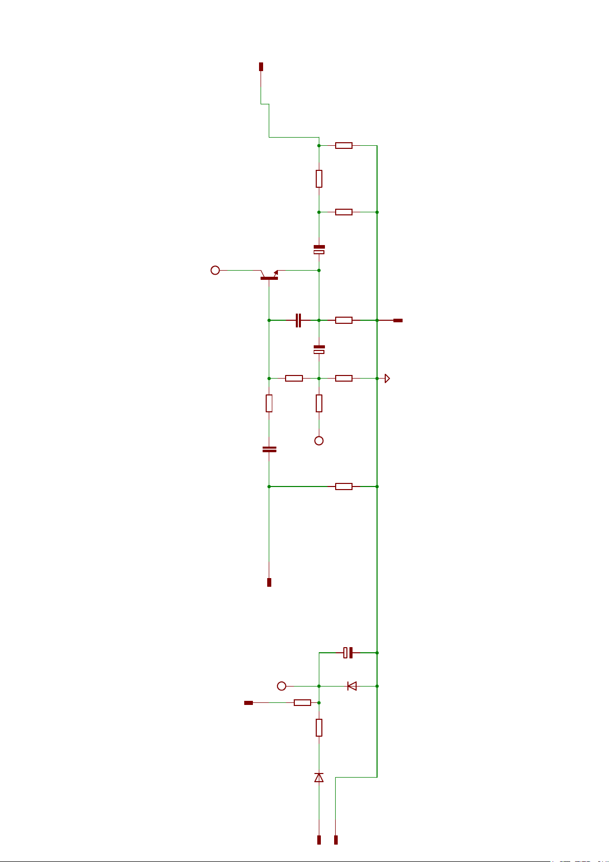
6 - SCHEMA ELETTRICO/SCHEMATIC
9. Test sonoro/Assembly test
Ottimo lavoro! Se tutti gli step descritti precedentemente sono
stati eseguiti correttamente, potete ora sigillare la parte poste-
riore della scatola, alimentare il pedale e fare un test sonoro. NB:
Utilizzare solamente alimentatori stabilizati e certicati.
Good job! If all previously described steps have been successful-
ly accomplished, you can now close the back plate of the enclo-
sure and you can make a sound test of your DIY pedal eect. NB:
Use only stabilyzed and certied power supply.
10. Risoluzione problemi/Trouble shooting
Nel caso di malfunzionamento del pedale assemblato far riferi-
mento alla sezione 9 per la risoluzione dei problemi.
In case of a malfunctioning pedal eect, you can follow our
tutorial on troubleshooting to solve the issues (see section 9).
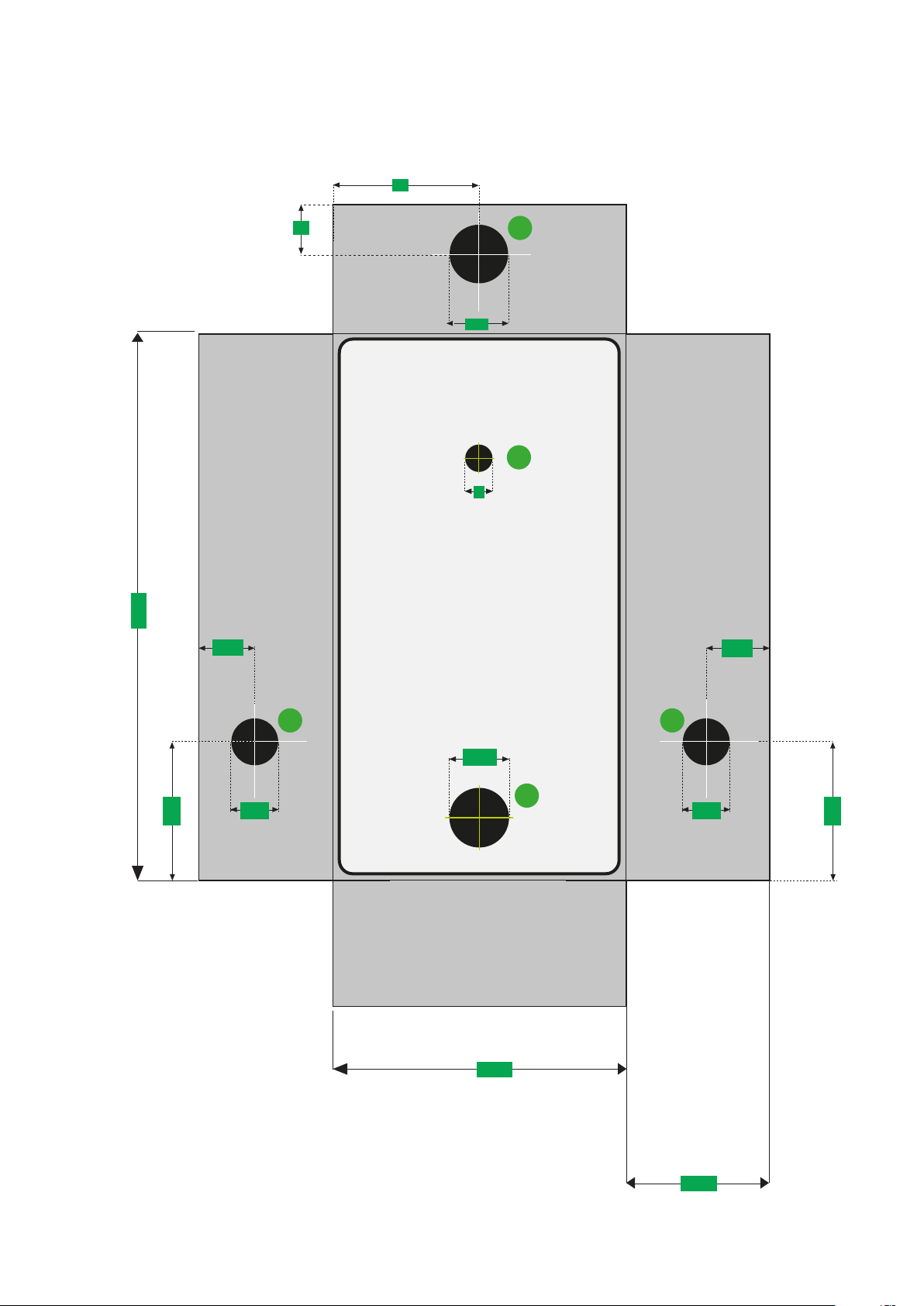
7 - MISURE DI RIFERIMENTO PER LA FORATURA /
REFERENCE MEASUREMENTS FOR DRILLING
59
27
110
9
29
29
10 10
13,3 13,3
3 5
1) DC1
2) L1+L2
3) J2
4) SW1
Misure espresse in millimetri / Measures in millimeters
5) J1
5
12,5
13
1
2
4
28
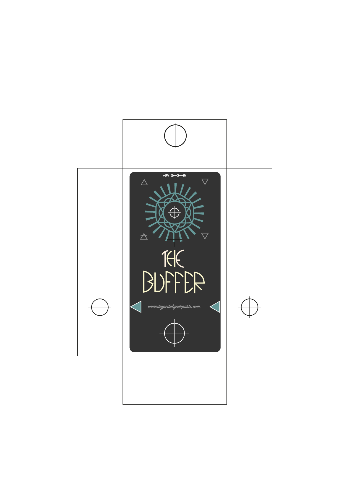
8 - TEMPLATE DI FORATURA / DRILLING TEMPLATE
Da stampare ed applicare sul box
To print and apply on the enclosure
DIMENSIONE REALE
LIFE SIZE
OUT IN
DIMENSIONI REALI
LIFE SIZE

?
Saldature fredde
Le saldature devono essere lucide (sinonimo di ottima connessione) e non opache (sinonimo di potenziale
saldatura fredda non buona). Qualora le saldature fossero opache, consigliamo di dissaldare e fare la salda-
tura di nuovo.
Posizione componenti, ponti ed interruzioni
Controllare che il circuito realizzato abbia tutti i componenti posizionati correttamente, vi siano i ponti
necessari e le interruzioni di traccia come indicato nel layout.
Orientamento dei componenti
Se ci sono problemi con un circuito caratterizzato da diodi, integrati e transistor, la prima cosa da fare è
controllare l’orientamento dei componenti stessi e quando necessario ricorrere alla scheda tecnica.
Misure elettriche
Se non si sono riscontrate problematiche con i controlli descritti in precedenza, il modo migliore per aron-
tare la situazione è misurare la tensione tra tutti i transistori, IC, regolatori e terra, controllando che vi sia
coerenza tra le misure fatte.
Qualora l’esecuzione delle attività descritte sopra non porti ad alcuna soluzione, si consiglia di costruire
un’audio probe (vedi sezione 10).
Importante: Internet ore diverse guide tecniche sull’utilizzo del multimetro per il controllo dei componen-
ti elettronici e della continuità elettrica.
Cold joints
The joints have to be glossy (good connection) and not opaque (bad connection). Are there any opaque
joins? If so, they should be removed and soldered again.
Components, jumpers and cuts
Check if all components have been laid down on the circuit correctly (double check having the circuit
layout or schematic at hand), check if the necessary jumpers have been correctly connected and the neces-
sary cuts also realized.
Orientation of the components
In case of a circuit characterized by diodes, ICs and transistor, it is recommended to check if the orientation
of those components is correct (refer to the component datasheet and electronic circuit layout).
Electric measurements
If no problems have been identied following the previously indicated steps, the best way to proceed is to
check if the voltage levels (use a multimeter) are correct involving the transistors, the IC, voltage regulators
and ground.
In case of no solution and all previous steps have been undertaken, it is suggested to build an audio probe
(see section 10).
Important: internet oers quite a lot of dierent tutorial concerning how to use a multimeter, how to mea-
sure electric continuity or how to measure the voltage levels in an electronic circuit.
Che cosa succede se dopo aver montato il nostro circuito non dovesse funzionare?
Di seguito alcuni step pratici che aiutano a capire come comportarsi per identicare il problema.
What happens if the assembled circuit does not work completely or properly?
The following steps are normally useful for an eective troubleshooting (in sequence).
9 - RISOLUZIONE DEI PROBLEMI/TROUBLE SHOOTING
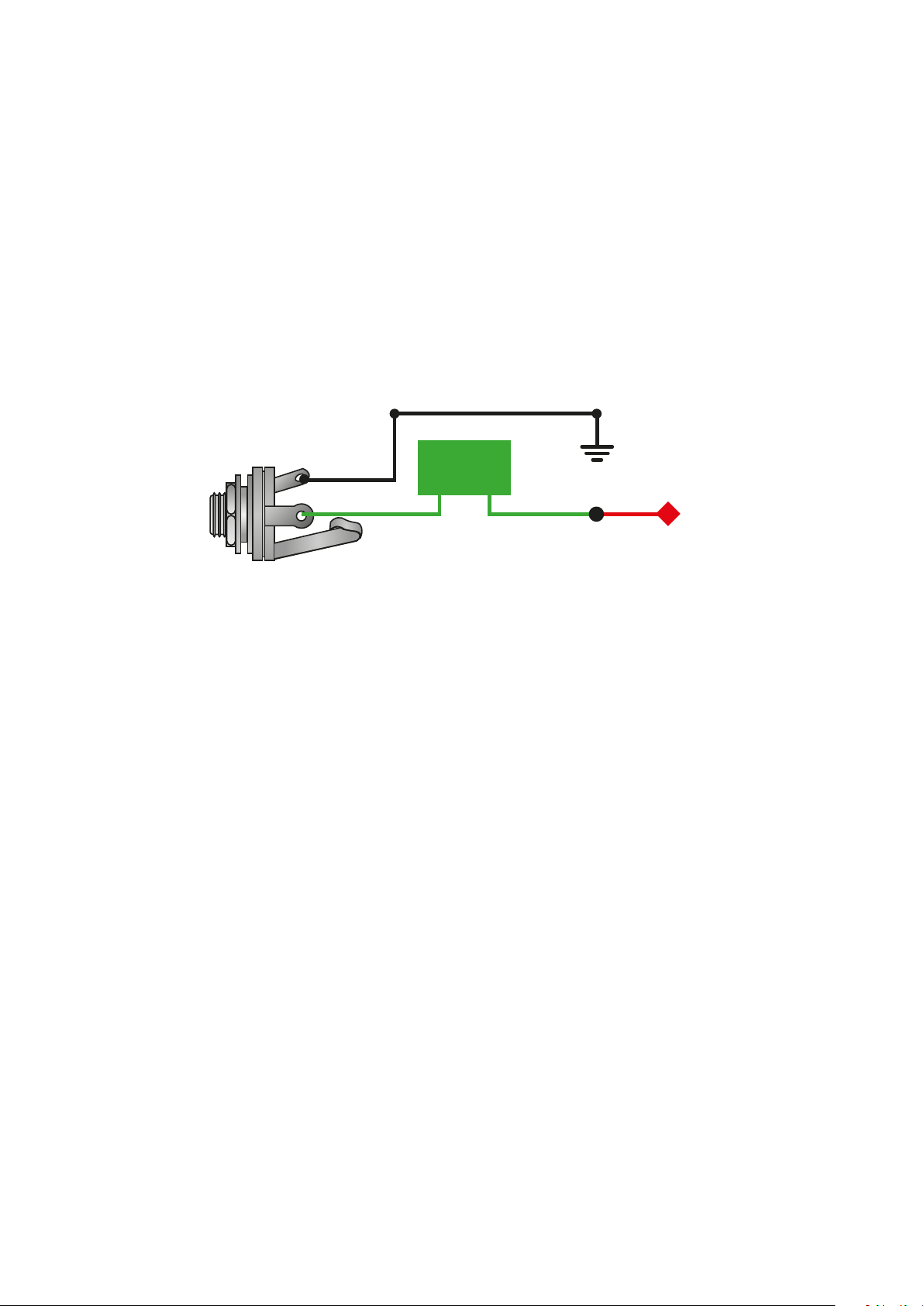
10 - AUDIO PROBE
L’audio probe è utilizzata come valido strumento
per il debugging dei circuiti e consente in buona
sostanza di seguire il segnale audio in input
lungo tutto il circuito, identicando dov’è che il
segnale si blocca ed aiutare nel risolvere even-
tuali problemi. La probe (3), che ciascuno può
costruirsi da sé, si compone come di seguente
(jack femmina da pannello mono, condensatore
da 100nF e puntale da tester o spezzone di lo
rigido per la probe):
The audio probe is used as a valid and eective
resource to debug electronic circuit for eect
pedals, allowing following the audio signal path
in the circuit from input to output and helping in
identifying where the problem in the circuit is
located.
The audio probe (3) can be assembled by anybo-
dy using the few described components: a
mono jack, a capacitor (100nF) and a multimeter
probe or a small piece of rigid electric wire for
the probe terminal itself:
First of all it is necessary to assemble the mono jack,
the capacitor and the multimeter probe or rigid
electric wire. After that the probe is connected to an
amplier or speaker (1) using an audio jack cable (2).
1) Connect an audio source in input at the electronic
circuit to debug and turn the amplier or the speaker
on: the audio source can be of dierent types (e.g.
mp3 player, an electric guitar);
2) Activate the electronic circuit (led on);
3) Follow the schematic of the electronic circuit from
the input to the output and position the probe on
dierent parts of the circuits to be tested. It is sugge-
sted to start from the input jack tip till the output jack
tip;
4) Once the probe is placed on a working trace/com-
ponent of the circuit, the amplier will reproduce the
audio signal given in input at the electronic circuit;
5) If the probe is placed on a faulty trace/component,
no audio signal will be reproduced by the amplier or
speaker: in this case it is necessary to intensify the
investigation around the faulty area;
6) What is the root cause of the issue? A faulty compo-
nent? A cold join?
7) In these cases it is necessary to replace the compo-
Una volta assemblati correttamente il jack mono
femmina, il condensatore da 100nF, il puntale o
lo rigido per la probe ed aver eettuato il colle-
gamento a massa, si procede collegando il tutto
ad un amplicatore per chitarra oppure ad cassa
acustica (1) tramite un cavo apposito (2).
1) Collegare una sorgente audio in input al circuito
elettronico (non alla probe): tale sorgente potreb-
be essere di qualsiasi tipo (per esempio un lettore
mp3);
2) Attivare il circuito elettronico che si sta control-
lando tramite 3PDT (led di stato acceso);
3)Seguendo lo schema del circuito elettronico,
seguire la traccia del segnale dall’input no
all’output, posizionando la probe sui diversi punti
del circuito/componenti che si intende testare. Si
consiglia
di iniziare dal tip del jack di input, attraversare il
circuito no al tip del jack di output;
4) Una volta sistemata la probe su una
traccia/componente funzionante, si sentirà
nell’amplicatore
o nella cassa acustica il segnale audio iniettato in
ingresso al circuito elettronico;
SHIELD
PROBE
GROUND
CAPACITOR
100nF
TIP
Componenti non inclusi nel kit/ Components not included in this kit
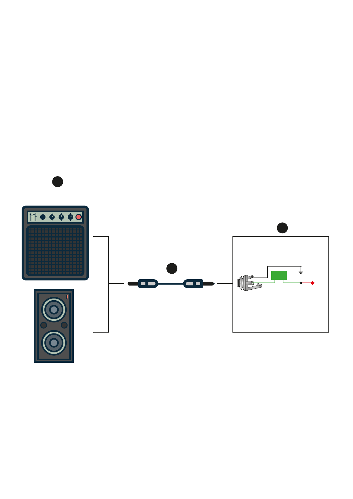
GUITAR AMPLI
O AUDIO SPEAKER
1
2
3
SHIELD
PROBE
GROUND
CAPACITOR
100nF
TIP
5) Qualora ponendo la probe sul circuito non
venisse emesso alcun segnale audio dall’ampli-
catore
o cassa acustica, è il caso di intensicare l’analisi
per capire dov’è che il segnale di blocca;
6) Che cosa causa il blocco del segnale? Un
elemento difettoso? Una saldatura fredda?
7) In questo caso si procede con la sostituzione del
componente o la modica della saldatura;
8) Tale procedimento può essere reiterato lungo
tutto il circuito elettronico nché sul TIP del jack
di output non si rileva il segnale proveniente dalla
sorgente audio in ingresso.
nent or to modify the cold joint;
8) The described procedure can be executed till the
electronic circuit works perfectly.
Componenti non inclusi nel kit/ Components not included in this kit

do it
yourself,
it’s better!

LEVEL
IN OUT
TONE
DRIVE
www.diypedalgearparts.com
ebay store: http://stores.ebay.it/diy-pedal-gear-parts
This manual suits for next models
1
Popular Music Pedal manuals by other brands


Marshall Amplification
Marshall Amplification EFFECT PEDAL ED1 COMPRESSOR owner's manual

Black Country Customs
Black Country Customs TI-BOOST manual

AXESS ELECTRONICS
AXESS ELECTRONICS AXSGTR OBViouS Boost/Overdrive user manual

Cusack-Music
Cusack-Music STEREO PEDAL TAMER quick start guide

Marshall Amplification
Marshall Amplification EFFECT PEDAL EH-1 ECHOHEAD owner's manual

aion
aion theseus manual


