DK-Technologies DK T7 User manual

1 | P a g e
DK T7
User Manual
DK T7 –Complete and Compliant

2 | P a g e
INTRODUCTION ...............................................................................................................................................4
BEFORE YOU BEGIN…............................................................................................................................................... 4
ABOUT THIS MANUAL............................................................................................................................................... 4
DK T7 VS.DK T7 STEREO –THE DIFFERENCE............................................................................................................... 4
OTHER IMPORTANT NOTES ....................................................................................................................................... 5
DK T7 –QUICK SHEET ............................................................................................................................................. 6
BASIC OPERATION ...........................................................................................................................................7
TOUCH ZONES &NAVIGATION................................................................................................................................... 7
AUTO STORING FEATURE IN THE DK T7....................................................................................................................... 7
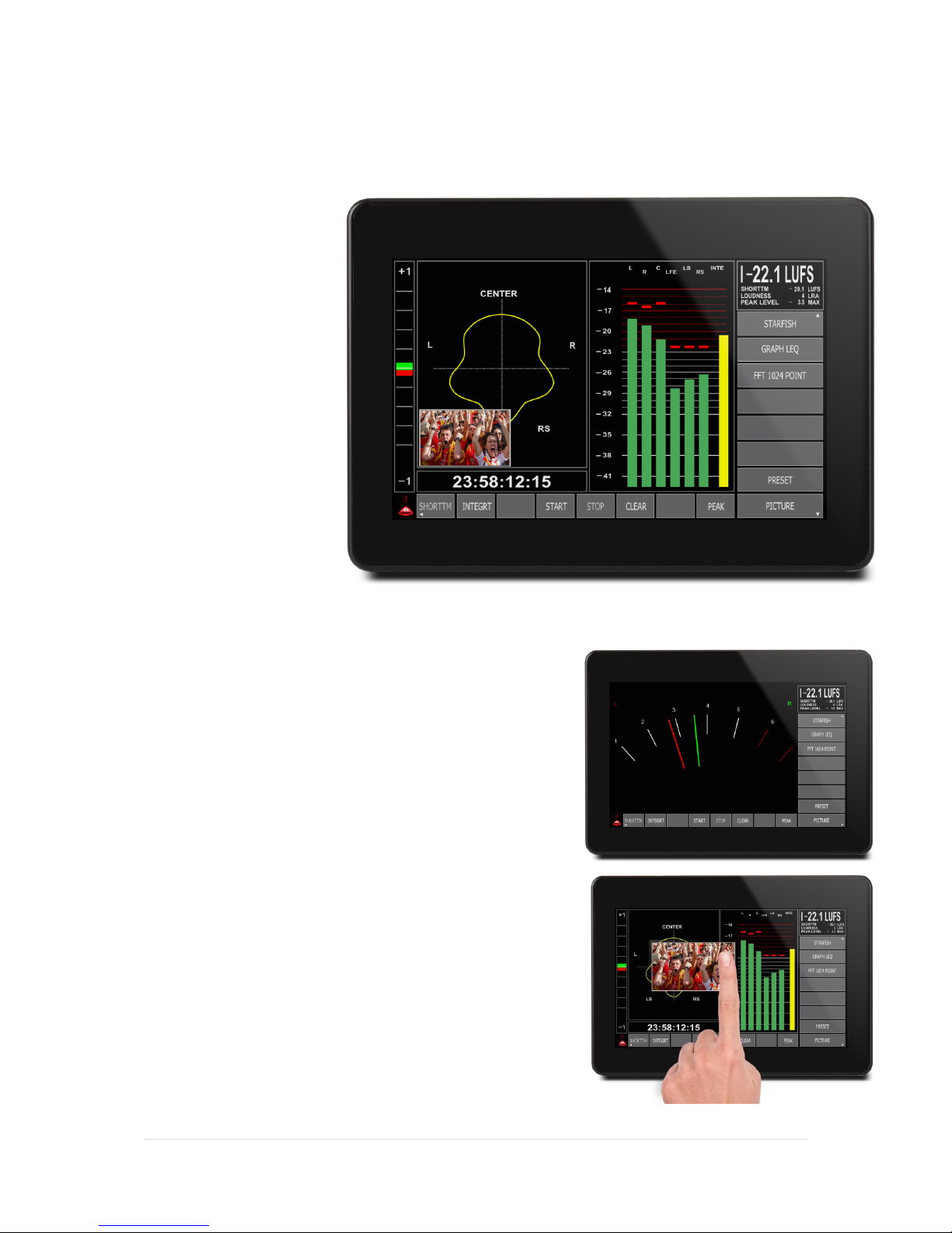
METER VIEWS –AN OVERVIEW .......................................................................................................................8
STARFISH VIEW ...................................................................................................................................................... 8
GRAPHICAL LEQ VIEW ............................................................................................................................................ 9
FFT 1024 VIEW ..................................................................................................................................................... 9
SOURCE & AUDIO ROUTING.............................................................................................................................9
UNDERSTANDING THE BASIC SIGNAL FLOW OF THE DK T7............................................................................................. 10
1-SOURCE SELECTION –CHOOSING YOUR INPUT........................................................................................................ 10
2-LABEL –NAMING YOUR INPUT SOURCE ................................................................................................................. 12
3-TYPE SELECTION –DEFINING THE ROLE OF YOUR SOURCE.......................................................................................... 13
SET UP BAR-GRAPH OPTIONS ........................................................................................................................15
COLOURS,COLOUR LEVEL &BAR-GRAPH WIDTH ........................................................................................................ 15
SET UP SCALE &LOUDNESS FORMAT ........................................................................................................................ 16
SET UP METER TEXT READ-OUT .....................................................................................................................21
SET UP STARFISH, TIME-CODE AND PHASE METER.........................................................................................22
TIME-CODE.......................................................................................................................................................... 23
‘ON-SCREEN’ BUTTON SETS HORIZONTAL & VERTICAL...................................................................................24
LOUDNESS AUTOMATION..............................................................................................................................27
LOUDNESS LOGGING......................................................................................................................................28
SETTING UP MOVING COILS ...........................................................................................................................28
USING DK-MATRIX SETUP EDITOR .................................................................................................................29
SET UP PICTURE PREVIEW..............................................................................................................................30
PRESET STORING ................................................................................................................................................... 31
NAMING A PRESET ................................................................................................................................................ 31
DEFAULT ‘POWER ON’PRESET ................................................................................................................................ 31
THE ADVANCED SETUP MENU........................................................................................................................32
THE SETUP MENU ................................................................................................................................................. 32
INSTRUMENTS & DISPLAY TOOLS ..................................................................................................................33
BAR-GRAPHS ........................................................................................................................................................ 33
EYE WIDTH .......................................................................................................................................................... 33
AES LOCK INDICATION ........................................................................................................................................... 33
GONIOMETER –VECTORSCOPE ................................................................................................................................ 34
PHASE CORRELATION.............................................................................................................................................. 34
STARFISH®........................................................................................................................................................... 34
JELLYFISH™.......................................................................................................................................................... 35
LOUDNESS BAR-GRAPH(S)....................................................................................................................................... 35
METER TEXT READ-OUTS ....................................................................................................................................... 35

3 | P a g e
RECLAIM FACTOR .................................................................................................................................................. 35
GRAPHICAL LOUDNESS ........................................................................................................................................... 35
FFT SPECTRUM ANALYZER ...................................................................................................................................... 36
MOVING COIL EMULATION ..................................................................................................................................... 36
LOUDNESS & TERMINOLOGY .........................................................................................................................37
ABOUT LOUDNESS................................................................................................................................................. 37
TERMINOLOGY...................................................................................................................................................... 37
TECHNICAL SPECIFICATION ............................................................................................................................39
DK T7 HARDWARE GPIO –EXTERNAL HARDWARE CONTROL ....................................................................................... 39
MECHANICAL DIMENSIONS AND MOUNTING .............................................................................................................. 40
DK T7 BACKPLANE CONNECTIONS............................................................................................................................ 41
DK T7 TOOLS OVERVIEW ....................................................................................................................................... 41
TECHNICAL SPECIFICATIONS..................................................................................................................................... 42

4 | P a g e
INTRODUCTION
Before you begin…
Thank you for purchasing one of the DK Meter family members.
With the DK T7 you are well equipped to meet the growing challenges within Audio and Loudness metering.
The DK T7 complies with all major Broadcast loudness standards and delivers outstanding
metering precision and clear read-outs, not merely on Loudness, but across the full range of audio metering
tools.
The DK T7 toolset makes it application-fit for any audio and loudness setup in broadcast, film & post production
as well as live transmission and recording.
With the clear DK T7 readout and compliance in your line of sight, you are always safe and sound.
About this manual
This manual will provide you with a quick overview of the DK T7 operation, tools and options, as well as an in-
depth look at the more advanced parameters and facilities of DK T7.
The manual covers the following product models:
DK T7
DK T7 Stereo
PT0T7
Software versions: 01052014
Happy reading!
Please note: DK-Technologies reserve the rights to change the content of this manual at any time. The latest
revision of this manual can be downloaded from: www.DK-Technologies.com
DK T7 vs. DK T7 Stereo –The Difference
The two models are very closely related and this manual covers both versions of DK T7 / Stereo.
The sheer difference is that while DK T7 includes SDI I/O and 8 ch. AES I/O, the DK T7 Stereo is limited to 2 ch.
of AES I/O and no SDI.
This means that any functionality and comment of this manual related to more than 2 inputs channels or SDI
signals is only relevant for the regular DK T7.
The product is referred to as DK T7 throughout this manual.

5 | P a g e
Other Important Notes
Disclaimer
No part of this document may be reproduced or transmitted in any form or by any means, electronic or
mechanical, including photocopying and scanning, for any purpose, without the prior written consent of DK-
Technologies A/S. The company aims to ensure that all details in this document are correct at the time of
publication, but reserves the right to alter specifications and equipment without notice. The latest version will be
available upon request. This publication is for international usage.
Despite considerable effort to produce up to date information, no literature published by the company nor any
other material that may be provided should be regarded as an infallible guide to the specifications available nor
does it constitute an offer for sale of any particular product.
StarFish and JellyFish are registered trademarks of DK-Technologies A/S. Dolby®E is a registered trade mark of
Dolby Laboratories, Inc. The ownership of any trademarks referenced is acknowledged.
© 2012 DK-Technologies A/S. E&OE. All Rights Reserved.
Purpose
Any fitness for purpose legislation or other determination that may be applied in the area where this equipment
is installed must take due cognizance that it is designed for use in professional broadcast, audio and video
systems by appropriately trained personnel. The equipment is not intended for use in a domestic environment
and regulations designed for such situations are not applicable.
After sales modifications
Any modifications to the equipment not specifically authorised and approved by DK-Technologies A/S may
invalidate the equipment warranty. This includes changes to cabling and variations to the recommended
installation as detailed in the documentation issued by DK-Technologies A/S. Modifications can invalidate EMC
and safety features designed into this equipment and the manufacturer cannot be liable for any legal
proceedings or problems that may arise relating to such modifications. No sales agent or other person involved in
the supply chain is permitted to authorise variations from the content of this documentation.
Important Safety Instructions
Read these instructions. Study carefully and understand all safety and operating instructions before you
install and operate the unit!
Keep these instructions. Keep all safety and operating instructions for future reference!
Heed all warnings on the unit and in the safety and operating instructions before you install and operate
the unit!
Follow all instructions to ensure against injury to yourself and damage to the unit or other objects
connected to the unit.
To prevent possible electrical shock, death, fire, injuries and malfunctions, use this product only as
specified.
Only use attachments and accessories specified by the manufacturer.
The units of the DK Meter range are designed for indoor use only

6 | P a g e
DK T7 –Quick Sheet
StarFish, Phase & TC Setup
Touch the Goniometer section to
setup change StarFish setup.
Choose your time-code source.
Change Scale & Loudness Setup
Touching the scale area allows access to Scale
setup, Loudness Setup and Display mode
(Moving Coil or Bar-graph)
Meter Source Select
Touch the legend of the meter sources, to
open and select from the list of input sources.
Sources may be named to your liking.
Text Read Outs
Touch the Text read outs to
setup specific parameters
viewed in the Text Field
Bar Graph Options
Change colours, Over/Normal/Under levels.
Assign ‘Type’ to specify what role the bar-
graph represents e.g. Left, Right or other.
Select / Customise
Press button for selecting
function.
Press & Hold for 3 secs to
change the function of the
button.
Slide between three button
sets.
Select / Customise
Press button for selecting function.
Press & Hold for 3 secs to change the function of the button.
Slide between three button sets: ‘Loudness’ – ‘Preset’ – ‘Main’
Naming Presets
Open Preset List.
Press & Hold ‘Preset name’
for 3 secs to name preset.
DK Logging Application
DK T7 includes complete
Loudness & True Peak Logging
Application that may be
downloaded free of charge
from:
www.dk-technologies.com
Exiting a Menu
Exit any menu by hitting the
Menu Headline box..

7 | P a g e
Basic Operation
Touch Zones & Navigation
The DK T7 is a multi-touch sensitive device allowing for both slides, tap and
Press & Hold functions.
The basic operation of the DK T7 is based on simply touch the area of the screen
that you would like to interact with.
Touching
Touching a specific area, will call up the relevant menu points and allow you to
alter settings in an instant.
Exiting a menu is always done by hitting the top menu bar on the left hand side.
Selecting a Parameter
When inside a menu, there are several ways of selecting a specific parameter.
1) Touching the desired parameter directly. This also used to open/close folders inside the menu structure
2) Sliding the menu until your parameter is in sight by simply sliding your finger up/down the screen on
the mid-left hand side of the menu
3) Moving the cursor to the desired position by sliding on the far right hand side of the menu.
Auto Storing Feature in the DK T7
The DK T7 features an ‘Instant Store’ facility that constantly stores any parameter change to the current preset.
This means that there is no need for manually storing presets, as your changes take effect at the moment of
performing them

8 | P a g e
Meter Views –an Overview
This section gives you a quick overview of the different views available in the DK T7.
StarFish View
The StarFish view, builds on
the heritage of the famous DK-
Technologies MSD meter range
and features a Vectorscope
alongside a bargraph section
allowing for both level and
loudness views. In addition, the
four text readouts are
displayed on the upper right
section of the screen.
In addition to the regular
meters and read-outs, the
StarFish view features a Time
code display below the
StarFish®, which allows you to
follow either the internal time-
code used during Loudness
automation or external SMPTE time code.
Moving Coil Mode
DK T7s StarFish view offers and alternative setup showing Moving coils
rather than bargraphs. There are two moving coil modes; ‘regular’ and
‘dual’ The ‘Moving Coil dual ’ mode allows you the ultra-wide Moving Coil
instrument displaying left and right channel in the same instrument,
while the regular mode will give you a separate moving coil instrument
for each input channel.
Picture Preview
The Picture preview confidence monitor, enables you to quickly monitor
the picture from the incoming SDI stream (3G/HD/SD) to ensure that you
are monitoring the correct stream. The Picture preview field may be
turned on/off or ‘dragged’ in position and resized to your liking.

9 | P a g e
Graphical LEQ
View
The Graphical LEQ view, allows
for several different
simultaneous views.
On top of the four standard text
readouts and phase meter, it
features level bar-graphs
adhering to the defined scale,
while the dual Loudness bars are
referring to the defined loudness
scale. In essence, this means
that two independent scales are
viewed at the same time.
Furthermore, the Loudness level
is plotted against time as a
graphical track on screen,
allowing for a historical view.
Loudness may also be logged via the DK Logging application against either internal time or external SMPTE time
code (free of charge).
Additionally, four extra text readouts may be defined on the top right section of the screen.
FFT 1024 View
The FFT view, simply features a
1024 band FFT spectrum
analyzer.
The FFT analyzer may be used
to check the spectral content of
individual channels in great
detail. This allows to check for
unwanted noise signals high and
low, as well as review the
spectral balance of your source
signal.
The FFT features detailed cursor
and Zoom functions allowing
ultra high precision spectral
review.
Source

10 | P a g e
& Audio Routing
Understanding the Basic Signal flow of the DK T7
As you are probably already aware, the DK T7 is a quite complex product with a lot of different signal routing
sources and destinations i.e. SDI, AES, Analogue as well as internal signal sources with destinations of
Bargraphs, Text Readout, StarFish, FFT, Loudness measurement and Downmix possibilities.
In order to simplify the overall routing, the DK T7 features a semi-automated routing scheme based on the
different signal source Types.
This allows you to simply select the appropriate source and type/role for your bargraph meter and DK T7 will
automatically define the rest of the routing.
For the same reason, it is very important for you to set up the bargraphs correctly, as this will define the rest of
the metering setup.
There are three important parameters to be aware of in setting up your Bargraph meter:
-Source Select –touching the top legend bar of the meter
-Source Label or Naming –touching the top legend bar of the meter
-Defining the Type of your source –touching the actual bargraph element
Reading through the below # 1, 2 and 3 sections will give you an understanding of the basic setup parameters.
1 - Source
Selection –
Choosing your input
Touch the Top bar to access the Source
Selection Menu

11 | P a g e
Touch the legend bar of the Bar-graph and the source selection list will open up
on the right hand side of the display.
Make sure to point to the specific bar-graph, that you want to alter the source
for.
The source selection allows you to choose between a number of Internal and
External sources (see below for details on the Source list)
Scroll the list to find the specific source that you are looking for.
The source chosen will be routed to the current bargraph –however, in order
to make sure that the source is routed correctly, you need to ensure that the
Label and Type set correct, please see section 2 and 3 for more details.
Source List
The Source list will display every available source on your meter including a
number of internal sources with special functions that we will get back to.
The sources are grouped in Internal, Analogue, Digital (AES) and De-embedded
(SDI) channels.
Each input source has a label as well as a unique ID number. While the label of
each source might be changed to your liking, the unique number ensures that it
is always possible to find out exactly what source you are working with.
Internal Sources
As mentioned, the Meter includes a number of internal sources that has specific functions like ‘Off’, Mix,
Difference, Loudness etc.
These come handy when setting up special functionality like a Loudness Bar-graph, adding MS indication to your
meter view or routing the internal Tone generator outputs.
Analogue Sources
The two balanced Analogue sources have their own group. In most presets the analogue sources are labelled
Left / Right respectively, assuming that they will be used for viewing an incoming signal.
The labelling of sources changes with the preset, so you might have different labels for the same source in
different presets. Please see ‘Label - Naming you input source’ section below for more information on renaming
your sources.
Digital –AES Sources
The 8 digital AES channels, like any other source has unique ID numbers.
Again, the specific labels of each of the sources will change with the preset.
De-embedded –SDI Sources
The 16 SDI de-embedded channels, like any other source has unique ID numbers.
Specific labels may be altered and is stored with the individual preset.

12 | P a g e
Source List
Group
Source –Label
# ID
Note
Internal
Off
1
No input
Internal
TonL
3
Left output of the internal Tone
Generator
Internal
TonR
4
Right output of the internal Tone
Generator
Internal
Mix
5
Mono/Mix signal from the internal
Downmix function
Internal
Diff
6
Difference signal from the internal
Downmix function
Internal
Loud
7
Output from the internal Loudness
measurement module
Analogue
e.g. L
33
Analogue input 1
Analogue
e.g. R
34
Analogue input 2
AES Digital
e.g. L, R, C, LFE, Ls, Rs
35-42
AES input channels 1-8
SDI De-embedded
1-16
129-144
SDI de-embedded channels 1-16
2 - Label –Naming your input source
Any input source label may be altered within each preset.
The DK T7 includes a default list of typical names for faster naming, but you might
also define your own.
The Default Label list contains the following labels:
L
CL
MR
R
CR
SMPT
C
CS
AUX1
LFE
DIFF
AUX2
LS
MIX
1-8
RS
ML
-
Here is how to change a label to one of the default labels:
-Open the ‘Source Selection’ menu by tapping the specific source label that
you want to change.
-In the ‘Source Select’ menu, Press and hold the label you want to change,
for approximately 3 seconds and watch the ‘Source Label Assign’ menu
pop up
-Now scroll to and tap the desired label e.g. ‘R’.
-Hit the left side of the Top Menu bar to Exit.
Creating your own Labels
Touch the Top bar to access the Source
Selection Menu

13 | P a g e
In addition to the default label list, you may design your own. The process to enter the Source Label Assign
menu is the same as above, but instead of selecting one of the default labels, scroll pass the default labels and
tap the header called ‘Edit Labels’. Below this header, you will see an additional 32 user labels that may be
customized to your liking.
-Hitting the ‘Edit Label’ header will bring up the keyboard and allow you to enter your desired label.
-Once satisfied, tap the label position that you want to carry the new name and hit ‘Done’ – this will save
the new label as well as attach it to the source that you started out with.
-Hit ‘Quit’ to leave the Keyboard
-Hit the left side of the Top Menu bar to Exit.
3 - Type selection –Defining the role of your
source
As mentioned earlier, the selection of the correct type or role of a specific source,
is essential to the automated routing of the source signal.
An example of why that is:
If your incoming source is defined as a ‘R’ right channel type, the DK T7
automatically knows that this source needs to be routed onto the Phase
correlation meter, the StarFish Right channel input as well as the Loudness
measurement block and the Downmix module.
In case the type was changed to ‘Ls’, the DK T7 would not only change inputs on
the various other metering, but also make sure to compensate gain when
calculating Loudness as per the BS1770 standard Loudness definition.
The Bargraph Options menu gives access to a lot of different bargraph parameters
that we will get to a bit later. For now, let’s make sure that the Type is set
correctly.
Hit the Header called ‘Labels Assign’ and you will see the different types.
Touch the Bargraph to access the Bargraph
Options Menu

14 | P a g e
INP
RS
L
CL
R
CR
C
CS
LFE
LOUD
LS
OFF
As might notice, a lot of these types are identical to some of the Default Source labels mentioned in the Label
section above. If you have chosen one of these default labels, you can simply select the Type to be ‘INP’ for
‘Input’. This means that that the DK T7 will look to the Input Source Label to learn what type of signal your
source is.
PLEASE NOTE: if the type is set to INP without having a relevant Source label selected, the Type will essentially
be ignored which could cause the source to not be routed to the appropriate instruments and measurements.
You can always manually select the specific Type that your source signal represents, in order to make sure that it
will routed correctly.
Hit the ‘Bar Options’ header on the left hand side to exit the menu.

15 | P a g e
Set Up Bar-graph Options
Colours, Colour level & Bar-graph Width
The Bar-graph options menu that we already talked about in the Source and
Audio Routing section, contains a number of other relevant parameters for
defining the look and behavior of your bar-graph elements i.e. Labels Assign,
Bargraph Width , Colour Normal, Colour Under, Under Level.
Touch the specific Bar-graph you want to alter, and the menu will open up on
the right hand side.
Labels Assign
This menu we already talked about earlier.
It allows you to assign one of the default labels
or make one of your own for each of the Bar-
graphs.
Bar-Graph Width
This section allows you to define the width of
each of the up-to 16 bar-graphs in the DK T7.
Please Note, that the DK T7 has an automated
scale function that will adapt both the StarFish and Bar-graph area to maximize the use of the display real
estate. This means that the more and the bigger the bargraphs are, the smaller the StarFish area becomes, until
it reaches its minimum size, in which case the bar-graph width is truncated.
Color Normal
Each scale includes a defined ‘Peak’ level where the
scale turns red. In addition to the Peak area, the DK T7
allows you to define colour of the ‘Normal’ area.
The ‘Colour Normal’ sets the color of each bar-graph
below the ‘Peak level’ in the ‘Normal’ area.
Colour Under
A threshold defines when the input signal is considered
‘under’ the ‘Normal’ level.
The ‘Colour Under’ sets the color of each bar-graph,
when below the defined threshold.
Touch the Bargraph to access the Bargraph
Options Menu

16 | P a g e
Under Level
Range: 0 to -25dB
The ‘Under Level’ determines when the signal is considered ‘Under’ the normal level.
Set Up Scale & Loudness Format
Touching the Scale area of the Bar-graphs will open up the Scale and
Loudness menu, allowing you to define what scale and Loudness format you
want your meter to adhere to.
The parameters in this menu counts: Scale, Under Level, Loudness Preset,
Loudness Setup, Loudness Option.
Scale
This section allows for a choice of numerous
different scales.
Here is the list of scales included in the DK T7:
Scale
Note
I
IEC 268 I –PPM Nordic
BBC
IEC 268 IIa
IIB
IEC 268 IIb –Transmission
DIN
DIN scale
VU
SMPTE V, +3/-20dB range
FBTV
DIN
NBC
Utra VU, 0/-60dB range
LEQM
RMS LEQ
ITU
RMS LEQ R128 scale
DMU1
DMU1630
DMU2
DMU1630 Zoomed 6dB range
40A
Dorrough 40A
40C
Dorrough 40C
EBU
IEC 268-18
WEBP
Web Peak –Digital scale
+3dBFS true peak
BBC
IEC268IIa + Shortterm
Loudness reading
Tap the desired scale for your meter.
Under Level
Range: 0 to -25dB
The ‘Under Level’ determines when the signal is considered ‘Under’ the normal level.
Loudness Preset
The Loudness setup parameter allows you to select between a number of standardized or recommended
Loudness settings including:
R128
ATSC A/85
LEQM
BCAP
TV2 DK
ABC-TV LA
HRTV-23FS
ARIB
AGCOM 219
If you select ‘User’, two additional folders opens up called Loudness Setup and Loudness Option.
These two folders enable you to completely customize the Loudness measurement to your exact specifications.
Touch the Scale area to access the Scale &
Loudness Menu

17 | P a g e
Loudness Setup
The Loudness Setup folder allows you to customize the loudness settings of your meter.
You may use one of the Loudness presets as a starting point.
Filter
Range: LEQM, K-Filter, Off
Sets weighting filter applied to the Loudness measurement.
ITU BS1770 loudness recommendation (R128, A/85) specifies K-filter weighting.
Scale Mode
Range: LU, LUFS, LKFS
The LU scale allows for a relative reference point in the loudness e.g. EBU R128 will mean 0LU=-
23LUFS, while SMPTE A/85 would mean 0LU = -24LKFS. The specific reference point may be
chosen via the ‘Reference’ parameter explained below.
LUFS and LKFS scales are identical scales, LUFS being used by EBU, while LKFS is used by
SMPTE.
Short-term Window
Range: Momentary, 3, 10 or 30 seconds.
The currently displayed loudness value is based on the averaged loudness values over the
defined time window. Setting the window to ‘Momentary’ essentially turns the Short-term
loudness reading into ‘Momentary’ loudness based on a sliding 300ms window. Please note that
the DK T7 already offers the Momentary reading alongside the Short-term loudness.
Reference
Range: -9 and -24 dBFS (1 dB steps).
A range of Reference levels can be chosen for the purpose of loudness measurement as part of
the loudness measurement standard which your organization (or client) has adopted.
EBU R128 specifies -23LUFS as the reference point.
SMPTE A/85 specifies -24LKFS as the reference point.
Peak Level
Range: -1 to -10 dBFS (1 dB steps).
The Peak level is a user defined reference point.
The peak level is dependent on the setting of ‘Peak Mode’; True Peak or Digital (Sample Peak).
When the signal passes above the peak level, the Peak level readout will turn Red.
Gate Level (-a)
Tip: Select the Loudness Preset that comes closest to your desired loudness setting, then select the ‘User’
Loudness Preset in order to customize the details.
Your changes will automatically be saved to the current preset.

18 | P a g e
Range: -8 to -20 dB (1 dB steps).
It is the high level parts of a program which are often of most interest for assessing compliance
with broadcast criteria. To prevent an extended length of low level program content reducing
the averaged loudness value to a degree that affects the measured value, the meter has an
optional gating function. Once the signal drops below the gate threshold, the meter will continue
to hold, display and use for averaging purposes, the previous value that was above the
threshold. Setting it to -20 causes the gate to remain open and the unit displays the actual
loudness for the vast majority of the time.
ITU BS1770 recommends a -10dB relative threshold for the loudness gate.
Gate Level (-b)
Range: Floating or Absolute.
The gate level can be an absolute value or a floating one. Absolute values offer a degree of
simplicity but at the risk of a high setting causing gating of quieter sections which might
sometime comprise a significant part of material such as a feature film soundtrack. Adopting a
low absolute value can cause background noise that is at a relatively high level (for example a
documentary by a waterfall) not to be gated out, even though it is not a significant contributor
to the perceived loudness. Making the gate level relative may then offer results that more closely
reflect perceived program loudness.
Most international loudness recommendations specifies a relative gating scheme.
Peak Mode
Range: Digital or True Peak.
Selecting Digital will base the reading on individual sample values.
True Peak uses oversampling to create the maximum intersample peak possible taken from the
maximum value of the interpolated waveshape.
ITU BS1770 specifies ‘True peak’ as the correct peak mode.
Reference
This is the frequency chosen for the calibration alignment and is either 400 or 1000 Hz.
Capture
The Loudness capture functionality may be changed between two different modes; Start-Pause
and Auto-Start.
Loudness measurement or Capture is essentially always done over a timespan - hence, it is
necessary to define when the Loudness capture starts and stops.
As explained in the Loudness & Terminology section, several different Loudness measures are
relevant i.e. Momentary Loudness, Short-term Loudness, Integrated Loudness and Loudness
Range –all time dependent.
The Start-Pause Mode
Is in effect a manual mode that allows you to decide when the Loudness capture starts, pauses,
restarts or is reset.
The button expresses the Loudness capture state the meter is in, e.g. ‘Start’ indicates that the
Loudness Captured has been started.
Loudness Capture is dependent on the incoming signal being higher than -70dBFS.

19 | P a g e
During the Loudness capture, you may now toggle the capture between ‘Start’ and ‘Pause’. The
overall resulting loudness readings will express the summarized capture of all audio above -
70dBFS from the last Reset.
Hitting ‘Reset’ will re-initiate the Loudness Capture and measures.
Overall, the Start-Pause mode allows you to manually start and stop the capture during breaks
or audio that you do not wish to consider in the overall loudness readings.
Auto-Start Mode
The Auto-Start mode, has controls and options similar to those of the Start-Pause Mode, with
the addition of an automatic start/reset facility triggered by the audio level.
More specifically, if the audio is higher than -70dBFS, the Loudness Capture is automatically
started, as well as being automatically stopped and Reset when the audio drops below -70dBFS
again for more than 2 seconds.
This mode is particularly handy when working with smaller bits of audio, and frees you from
having to manually reset the loudness capture every time you want a new reading.
Loudness Option
The Loudness option section allows you define what loudness parameter you wish displayed as the Loudness
bar-graph as well as setting up the Capture mode of your loudness measurements.
Capture
The Loudness capture functionality may be changed between three different modes; Start-
Pause, Auto-Start and Auto-LTC.
Loudness measurement or Capture is essentially always done over a timespan - hence, it is
necessary to define when the Loudness capture starts and stops.
As explained in the Loudness & Terminology section, several different Loudness measures are
relevant i.e. Momentary Loudness, Short-term Loudness, Integrated Loudness and Loudness
Range –all time dependent.
The Start-Pause Mode
Is in effect a manual mode that allows you to decide when the Loudness capture starts, pauses,
restarts or is reset.
The button expresses the Loudness capture state the meter is in, e.g. ‘Start’ indicates that the
Loudness Captured has been started.
Loudness Capture is dependent on the incoming signal level being higher than -70dBFS.
During the Loudness capture, you may now toggle the capture between ‘Start’ and ‘Pause’. The
overall resulting loudness readings will express the summarized capture of all audio above -
70dBFS from the last Reset.
Note: As per the BS1770 standards, audio below -70dBFS is not included in the overall
loudness capture. This is to avoid that breaks or silence in the audio undermines the
loudness readings.
Note: Enabling a Loudness Bar-graph requires audio to be routed to the relevant bar graph position.

20 | P a g e
Hitting ‘Reset’ will clear the loudness Capture and measurements.
Overall, the Start-Pause mode allows you to manually start and stop the capture during breaks
or audio that you do not wish to consider in the overall loudness readings.
Auto-Start Mode
The Auto-Start mode, has controls and options similar to those of the Start-Pause Mode, with
the addition of an automatic start/reset facility triggered by the audio level.
More specifically, if the audio is higher than -70dBFS, the Loudness Capture is automatically
started, as well as being automatically stopped and Reset when the audio drops below -70dBFS
again for more than 2 seconds.
This mode is particularly handy when working with smaller bits of audio, and frees you from
having to manually reset the loudness capture every time you want a new reading.
Auto-LTC –Loudness Automation
The Auto-LTC mode automates the Loudness capturing based on incoming LTC / SMPTE time
code.
This is an extremely efficient audio production mode, as it features instant recalculation of all
Loudness capture results when editing even tiny bits of the audio clip.
Imagine wanting to measure and adjust loudness for an audio clip of 5 minutes, but really only
altering the audio in a section of 30 seconds. This would normally mean that you would have to
allow the Loudness measurement to go over the entire 5 minutes after every edit.
With the Loudness Automation feature, the DK T7 automatically identifies what section of the
audio is being altered based on the incoming time code and instantly recalculates the complete
loudness result.
Please see the ‘Loudness Automation’ section for further details on how set this up.
Loudness Display
The Loudness parameters available for display are the following:
Momntry –‘Momentary Loudness’
Shorttrm–‘Short-term Loudness’
Integrt –‘Integrated Loudness’
None –Meaning no Loudness Bar graph displayed
Momentry+Shortterm –both readings alongside each other
Note: As per the BS1770 standards, audio below -70dBFS is not included in the overall
loudness capture. This is to avoid that breaks or silence in the audio undermines the
loudness readings.
Table of contents
Other DK-Technologies Measuring Instrument manuals
Popular Measuring Instrument manuals by other brands

Campbell
Campbell IRGASON product manual

Magnescale
Magnescale LY71 Quick reference manual

DVR365
DVR365 MPEG 4 manual

Zircon
Zircon StudSensor i60 OneStep quick start guide

Emerson
Emerson Daniel 3410 Series Instructions for use, maintenance and installation

Leviton
Leviton Verifeye 8000 Series Installation and user manual