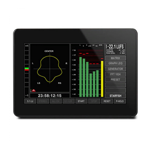
DK-Technologies RAP-B-138U User manual

1
DK METER –Audio & Loudness Metering Complete
DK METER
User Manual

2
INTRODUCTION ...............................................................................................................................................4
BEFORE YOU BEGIN…............................................................................................................................................... 4
ABOUT THIS MANUAL............................................................................................................................................... 4
OTHER IMPORTANT NOTES ....................................................................................................................................... 5
QUICK GUIDE ...................................................................................................................................................6
IF YOU JUST WANT TO GET GOING ............................................................................................................................... 6
BASIC OPERATION ...........................................................................................................................................7
MOUNTING YOUR DK METER.................................................................................................................................... 7
POWER SUPPLY....................................................................................................................................................... 7
NAVIGATION .......................................................................................................................................................... 7
SLIDING WINDOWS AND VIEWS ................................................................................................................................. 8
MENU NAVIGATION ................................................................................................................................................ 8
THE PRESET AND QUICK SETUP ........................................................................................................................9
STEP 1- PRESET LIST ................................................................................................................................................ 9
STEP 2-INPUT AND CHANNEL ORDER ....................................................................................................................... 10
STEP 3-SCALE AND LOUDNESS SETUP....................................................................................................................... 10
STEP 4-METER TEXT READ OUT ............................................................................................................................. 11
UPGRADE OPTION TRIAL ........................................................................................................................................ 12
HOW TO ….......................................................................................................................................................... 12
BACKLIGHT AND STANDBY....................................................................................................................................... 12
METER VIEWS –AN OVERVIEW .....................................................................................................................12
PORTRAIT BARGRAPH (VIEW 1) ............................................................................................................................... 12
GRAPHICAL LOUDNESS PORTRAIT (VIEW 2)................................................................................................................ 13
HORIZONTAL GRAPHICAL LOUDNESS (VIEW 3)............................................................................................................ 13
MSD VIEW MODE (VIEW 4) ................................................................................................................................... 13
FFT MODE (VIEW 5).............................................................................................................................................. 13
HORIZONTAL BARGRAPH (VIEW 6) ........................................................................................................................... 14
METER SETUP & AUDIO ROUTING .................................................................................................................15
AUTOMATED METER SETUP .................................................................................................................................... 15
CLOCK SETUP AND HIERARCHY................................................................................................................................. 15
AUDIO ROUTING SETUP.......................................................................................................................................... 15
THE ADVANCED SETUP MENU........................................................................................................................18
THE SETUP MENU ................................................................................................................................................. 18
ABOUT –USER MODE &USER RESTRICTIONS ............................................................................................................ 18
PRESET –FOLDER.................................................................................................................................................. 19
MATRIX OUTPUT ASSIGN –SELECTING YOUR METER SOURCE........................................................................................ 19
METER SETUP ...................................................................................................................................................... 19
STARFISH™SETUP ................................................................................................................................................ 20
LOUDNESS PRESET................................................................................................................................................. 21
LOUDNESS SETUP .................................................................................................................................................. 21
LOUDNESS OPTION................................................................................................................................................ 23
LABELS ASSIGN ..................................................................................................................................................... 24
AUDIO GLOBAL..................................................................................................................................................... 24
INSTRUMENTS & DISPLAY TOOLS ..................................................................................................................25
PORTRAIT BAR-GRAPHS .......................................................................................................................................... 25
EYE WIDTH .......................................................................................................................................................... 25
AES LOCK INDICATION ........................................................................................................................................... 26
GONIOMETER –VECTORSCOPE ................................................................................................................................ 26
PHASE CORRELATION.............................................................................................................................................. 26

3
STARFISH™.......................................................................................................................................................... 26
JELLYFISH™.......................................................................................................................................................... 27
LOUDNESS BAR-GRAPH(S)....................................................................................................................................... 27
METER TEXT READ-OUTS ....................................................................................................................................... 27
RECLAIM FACTOR .................................................................................................................................................. 28
GRAPHICAL LOUDNESS ........................................................................................................................................... 28
FFT SPECTRUM ANALYZER ...................................................................................................................................... 28
MOVING COIL EMULATION ..................................................................................................................................... 29
DK LOGGING PC APPLICATION ................................................................................................................................ 29
HOW TO….. ....................................................................................................................................................30
HOW TO GET LANDSCAPE AND MSD VIEW ................................................................................................................. 30
HOW TO ENABLE FFT SPECTRUM ANALYZER................................................................................................................ 30
HOW TO SET ANALOG INPUT SENSITIVITY ................................................................................................................... 30
HOW TO SWITCH TO MOVING COIL EMULATION ......................................................................................................... 30
HOW TO CHANGE THE BAR-GRAPH WIDTH.................................................................................................................. 30
HOW TO CUSTOMIZE WINDOW TEXT READ OUT.......................................................................................................... 30
HOW TO SOFTWARE UPDATE ................................................................................................................................... 31
HOW TO UPGRADE YOUR METER.............................................................................................................................. 31
HOW TO CLONE THE SETTINGS FROM ONE UNIT TO ANOTHER......................................................................................... 31
HOW TO VIEW TWO STEREO PAIRS WHILE WATCHING LOUDNESS BASED ON PAIR #1........................................................... 32
LOUDNESS & TERMINOLOGY .........................................................................................................................33
ABOUT LOUDNESS................................................................................................................................................. 33
TERMINOLOGY...................................................................................................................................................... 33
OTHER RELEVANT INFO..................................................................................................................................35
THE DK METER FAMILY.......................................................................................................................................... 35
DK METER ONLINE APPLICATION (PC SOFTWARE) ...................................................................................................... 35
SIGNAL CONNECTIONS ............................................................................................................................................ 36
SPECIFICATIONS .................................................................................................................................................... 38

4
Introduction
Before you begin…
Thank you for purchasing one of the DK Meter family members.
With the DK Meter you are well equipped to meet the growing challenges within Audio and Loudness metering.
The DK Meter complies with all major Broadcast loudness standards and delivers outstanding
metering precision and clear read-outs, not merely on Loudness, but across the full range of audio metering
tools.
The DK Meter toolset makes it application-fit for any audio and loudness setup in broadcast, film & post
production as well as live transmission and recording.
With the clear DK Meter readout and compliance in your line of sight, you are always safe and sound.
Flexible & User definable
The DK Meter range holds a wide selection of audio measuring tools, including Loudness measurements
compliant with all major broadcast standards.
With an open and flexible approach, DK Meter leaves it up to you to decide exactly what tools, read-outs, scales
and labels you would like to use.
Your setups can be stored and recalled as user defined presets, allowing you to adapt your desired meter views
on the fly.
About this manual
This manual will provide you with a quick overview of the DK Meter operation, tools and options, as well as an
in-depth look at the more advanced parameters and facilities of DK Meter.
Happy reading!
Please note: DK-Technologies reserve the rights to change the content of this manual at any time. The latest
revision of this manual can be downloaded from:
www.DK-Technologies.com

5
Other Important Notes
Disclaimer
No part of this document may be reproduced or transmitted in any form or by any means, electronic or
mechanical, including photocopying and scanning, for any purpose, without the prior written consent of DK-
Technologies A/S. The company aims to ensure that all details in this document are correct at the time of
publication, but reserves the right to alter specifications and equipment without notice. The latest version will be
available upon request. This publication is for international usage.
Despite considerable effort to produce up to date information, no literature published by the company nor any
other material that may be provided should be regarded as an infallible guide to the specifications available nor
does it constitute an offer for sale of any particular product.
StarFish and JellyFish are registered trademarks of DK-Technologies A/S. Dolby®E is a registered trade mark of
Dolby Laboratories, Inc. The ownership of any trademarks referenced is acknowledged.
© 2012 DK-Technologies A/S. E&OE. All Rights Reserved.
Purpose
Any fitness for purpose legislation or other determination that may be applied in the area where this equipment
is installed must take due cognisance that it is designed for use in professional broadcast, audio and video
systems by appropriately trained personnel. The equipment is not intended for use in a domestic environment
and regulations designed for such situations are not applicable.
After sales modifications
Any modifications to the equipment not specifically authorised and approved by DK-Technologies A/S may
invalidate the equipment warranty. This includes changes to cabling and variations to the recommended
installation as detailed in the documentation issued by DK-Technologies A/S. Modifications can invalidate EMC
and safety features designed into this equipment and the manufacturer cannot be liable for any legal
proceedings or problems that may arise relating to such modifications. No sales agent or other person involved in
the supply chain is permitted to authorise variations from the content of this documentation.
Important Safety Instructions
Read these instructions. Study carefully and understand all safety and operating instructions before you
install and operate the unit!
Keep these instructions. Keep all safety and operating instructions for future reference!
Heed all warnings on the unit and in the safety and operating instructions before you install and operate
the unit!
Follow all instructions to ensure against injury to yourself and damage to the unit or other objects
connected to the unit.
To prevent possible electrical shock, death, fire, injuries and malfunctions, use this product only as
specified.
Only use attachments and accessories specified by the manufacturer.
The units of the DK Meter range are designed for indoor use only

6
Quick guide
If you just want to get going
If you just want to get going with your new DK Meter right away, here are a few simple steps to get it up and
running.
1. Connect the included power supply or power your meter directly from your computer USB port.
2. Powering up your meter, you will see the on-board quick setup guide –if you want to disregard that,
slide across the three touch buttons from left-to-right (you can always return to the guide later).
3. Connect the DK Meter AES 1 to the appropriate audio output and play audio.
4. You will now see the default meter view in stereo or surround sound depending on your model and
options (fig xx). This view includes four main sections:
Meter Text Readouts –Integrated Loudness, Reclaim factor, Loudness Range and Peak Level
(true peak)
Digital PPM –Showing True Peak
Vectorscope/GonioMeter –Showing sum/difference content
Phase Correlation –showing phase information
For more information on the individual tools, please refer to the ‘display tools and options’ section of this manual.
Meter Text Readouts
PPM –True Peak
Phase Correlation
Vectorscope

7
Basic Operation
Mounting your DK Meter
The DK Meter is supplied with an adjustable mounting bracket. The top piece is
mounted onto the DK Meter with the two included screws, while the desktop
piece is mounted with four screws.
Additional fixing options and mounts are available from DK-Technolgies.com or
from RAM on http://www.rammount.com .
The included model number is: RAP-B-138U
Power Supply
The DK Meter comes with a plug-top power supply with a USB outlet. If being
used in conjunction with a computer or USB hub, any conventional USB-A outlet
with the standard USB 5 volt supply may be used instead of the included power
supply unit.
This elegant feature not only makes the DK Meter easier to bring along, but also
conveniently allows the DK Meter to power up with the relevant computer of your
setup.
Navigation
The general navigation on the DK Meter is achieved through the three capacitive touch sensitive buttons below
the screen.
Each touch button corresponds to the on-screen button and dynamically changes name as relevant.
In addition, swiping across the three buttons from left-to-right or vice versa, allows you to change the overall
meter view or selected menu.
Note: When fixing the mounting plate to the rear of the meter, use only
the screws supplied –damage may be caused by using longer screws, or
different mounting back plate.

8
View2
PPM
+Loudness
History
View1
PPM +
Vector-
scope
Advanced
Setup
Menu
Sliding Windows and Views
The sliding function described above allows you to easily move from one meter setup to another, as well as
entering the background Quick setup, preset and Setup menus. Here is a quick overview of the immediate
windows that you can slide between:
In every DK Meter there are four basic meter views in addition to ‘Preset and Quick Setup’ Menu and the
‘Advanced Setup Menu’. The three meter views are; PPM+Vectorscope, PPM Loudness history and Horizontal
Loudness history and Horizontal Bargraph. Additionally, the DK4 meter features another two landscape views
which may be obtained for DK1, DK2 and DK3 as software upgrades i.e. the ‘MSD Landscape Views’ and the FFT
analyzer.
See more details about the individual meter views in the Meter View Section of this manual.
Menu Navigation
When inside a menu (Quick setup or Advanced setup), the three touch buttons become your navigation. The left
most button moves the cursor up, the center button moves the cursor down and the right most button becomes
a ‘select’ function.
At any point is it possible to ‘slide’ across the buttons to exit the current menu.
In several of the menus, a folder structure has been designed to hold the many parameters and functions of the
DK Meter.
To open or close a folder, move the cursor on top of the folder and press ‘select’. You are now exposed to the
folders inside, including potential sub-folders.
Tip: Selecting an empty line and hitting ‘Select’ will close the current folder.
View5
FFT
(Optional)
View4
MSD View
(Optional)
View3
PPM +
Loudness
Quick
Setup
Menu
View6
Horizontal
Bargraph

9
The Preset and Quick Setup
When powering up your meter for the first time, the ‘Preset and Quick Setup’ menu will be shown as the first
display.
The Preset and Quick Setup menu, allows for a simplified and fast way of setting up you DK Meter. More
advanced settings and functions are edited in the ‘Setup’ menu reached by sliding from right to left.
The Quick Start Guide will give you a few basic tips on operation and setting up your meter.
Let’s walk through the different folders:
Here are the four simple steps to follow to set your
meter up in a few minutes:
Step 1 Preset List –Select the preset you
want to work with
Step 2 Input and Channel Order –Select
your preferred input and choose your
desired Loudness bar-graph
Step 3 Scale and Loudness Setup –Select
your Scale and Loudness setup of choice
Step 4 Meter Text Read Out –Define what
four parameters you want to see on the Meter
Text Read Out.
Step 1- Preset List
The DK Meter holds a list of presets that allows you a fast starting point,
as well as showcasing some of the different tools included in the Meter.
Any of the presets can be edited to become a custom user preset.
Selecting a preset is as easy as moving the cursor to the desired preset on the list and hitting the ‘Select’ button.
DK Meter always has a preset selected and changes are instantly stored upon exiting to the Meter view, be it;
meter setup, background parameters and display appearance.
Dynamic preset naming
When advancing in the Quick Setup, the selected preset name will dynamically reflect your choices.
The dynamic preset name includes the following information:
Input Source –channel count and Order –Loudness Setup - Scale
Note: The power-up showing of the Quick Start Guide may be disabled by unchecking the ‘Show this panel
on power up’ parameter (the change is stored upon exiting to the meter viewings).

10
Dynamic Preset Example
The naming of a preset may be customized in the ‘Advanced Setup Menu’ under the Audio Global/Preset Folder
(see more in the ‘Setup Menu’ section).
Step 2 - Input and Channel Order
The Input and Channel Order section allows you to easily select both your
preferred input source and the order of the incoming channels.
The list of input and channel order only displays inputs and channel setups
allowed by the current meters specific hardware and software configuration.
More advanced input and channel routings may be accessed in the Advanced Setup Menu.
The following inputs may appear depending on your specific Meters ability and interfaces:
Analogue
Digital
De-embed
All interfaces may be selected as 2.0, while only Digital and De-Embedded allows for 5.1 setups.
5.1 setups allow for two different channel orders:
LRC –corresponding to the EBU channel order: Left, Right, Center, LFE, Ls, Rs
LCR –corresponding to the SMTPE channel order: Left, Center, Right, Ls, Rs, LFE
Choosing ‘User Def’ will make the meter fall back on the settings of the more advanced ‘Setup’ menu, allowing
you to tailor input source and channel order in more advanced ways than those offered in the Quick Setup.
Step 3 - Scale and Loudness Setup
This menu allows you to define exactly what scale and specs your bar graphs
should perform to.
Select the desired scale by moving the cursor in place and hit ‘Select’.
The scale list includes:
IEC 268 I
BBC –IEC 268 II
IIB –IEC 268 II
DIN
SMPTE VU
FBTV –DIN
NBC –Ultra VU
LEQM –RMS LEQ
ITU –RMS LEQ
DMU1 –DMU1630
DMU2 –DMU1630
40A –Dorrough
40C –Dorrough
EBU –IEC 268-18
Web Peak
PPM4 –Loud 10
Any scale will be applied to the chosen Meter view.
However, one scale stands out and
Digital Input
5.1 Surround
LCR channel
order
Integrated
Loudness
Bar-graph
R128 Loudness
Setup
LEQM Meter scale

11
Graphical Bar-graph Width
The graphical width of the bar-graphs may be altered. If set to ‘Auto’, the Meter will dynamically adapt the
width. Selecting ‘Normal’ will allow you to manually define the width in the ‘Setup’ Menu.
Please see the ‘Setup Menu’ section for further details on the ‘Normal’ or manual width definition.
Loudness Setup
The Loudness setup parameter allows you to select between a number standardized or recommended Loudness
settings including:
R128
ATSC A/85
LEQM
BCAP
TV2 DK
ABC-TV LA
HRTV-23FS
ARIB
AGCOM 219
If you select ‘User’ the loudness setup may be completely customized to exactly your specifications in the ‘Setup
Menu’.
Please see the ‘Setup Menu’ section for further details on the ‘Normal’ or manual width definition.
Loudness Bar Type
Allows you to define if you want to see a Loudness bar next to your other Bar graphs and if so, what Loudness
parameter will be indicated:
Momntry –‘Momentary Loudness’
Shorttrm–‘Short-term Loudness’
Integrt –‘Integrated Loudness’
None –Meaning no Loudness Bar graph displayed.
Momentary+Shorttrm –Dual Loudness bars of both ‘Momentary’ and ‘Short-term’ Loudness
Step 4 - Meter Text Read Out
The Meter Text Read Out allows you to customize what parameter each of
the four Text read outs in the top the DK Meter screen displays.
Each of the four parameters has its own folder with the parameters that
are possible to display as a Text Read out.
NOTE: The Loudness Capture mode may be set to automatic or manual. The Default setting is ‘Auto’ and
initiates the Loudness measurement when incoming audio passes the above a -70dBFS threshold.
Please refer to Advanced Setup Menu/Loudness Setup/Capture for more information
Line 1
Line 2
Line 3
Line 4

12
Upgrade Option Trial
Every DK Meter comes with all Upgradable options running on a 180 hour trial
time. This effectively means that you have the chance of checking out various
functions and features before making up your mind on potential upgrades.
The Upgrade Option Trial folder shows you how many trial hours you have left
before the Upgrade functions will be shut off.
For further information on Software Upgrades, please refer to the ‘How to
Upgrade Your Meter’ section of this manual.
The DK Meter family overview of upgrade and included options can be view in ‘The
‘DK Family’ section.
How to …
The Quick Setup features a few ’How to...’ descriptions.
Please refer to the complementary ‘How to…’ section of this manual for a detailed description and tips on how to
perform specific tasks using the DK Meter.
Backlight and Standby
The backlight parameter allows you to set the brightness of your meter. Hit the ‘Select’ button and use arrow
up/down to set the desired backlight level. De-select the backlight parameter by hitting ‘Select’ again.
The Standby parameter enables the meter to be put into standby mode. Hit any of the three touch sensitive
buttons to wake up your meter.
Meter Views –an Overview
This section gives you a quick overview of the different views available in the
Portrait Bargraph (View 1)
The Portrait bargraph view features a number simultaneous
viewings and readouts.
The default functions of this view includes 4 text readouts at the
top, level bargraphs and the option of adding phase and
vectorscope at the bottom of the view.
The Loudness indication may be a single or dual bargraph,
allowing for two different loudness parameters to be viewed at
the same time.
In addition to the traditional bargraphs, this view also has the
ability to show level and loudness as moving coil emualations.
The moving coil emulation may be changed here:
Adv. Setup/Preset/Meter Setup/Display mode

13
Graphical Loudness Portrait (View 2)
The graphical loudness view, allows for several different
simultaneous views.
On top of the four standard text readouts and phase meter, it
features level bargraphs adhering to the defined scale, while the
dual Loudness bars are referring to the defined loudness scale. In
essence, this means that two independent scales are viewed at the
same time.
Furthermore, the Loudness level is plottet against time as a
graphical track on screen, allowing for a historical view.
Horizontal Graphical Loudness (View 3)
The horizontal graphical loudness view features a similar set of option as
the portrait version of this view. Additionally, four more text readouts
may be defined on the top right section of the screen. The specific
parameters view may be changed here:
Adv. Setup/Preset/Loudness Option/Window Text
MSD View mode (View 4)
The MSD View, builds on the heritage of the famous DK-Technologies
MSD meter range and features a Vectorscope alongside a bargraph
section allowing for both level and loudness views. In addition, the four
text readouts are displayed on the upper right section of the screen.
As an extra option, the MSD View may be changed to display moving
coil emulations instead of bargraphs.
The moving coil emulation may be changed here:
Adv. Setup/Preset/Meter Setup/Display mode
The ‘Moving Coil Dual’ mode allows you the ultrawide Moving Coil
instrument displaying left and right channel in the same instrument
FFT mode (View 5)
The FFT view, simply features a 1024 band FFT spectrum analyzer.
Please check out the Instrument & Display tools section of this manual
for further information specifically on this tool.

14
Horizontal Bargraph (View 6)
The Horizontal bargraph view, in addition to the regular Text readouts,
vectorscope and phase meter, features a horizontal bargraph view.

15
Meter Setup & Audio Routing
Automated Meter Setup
As you are probably aware by now, the DK Meter is quite a complex piece of equipment.
In order to simplify setup, the DK Meter has an integrated auto setup function that ensures that bar-graphs,
loudness, vectorscope and other instruments has pre-wired inputs. For example; the bar-graphs will
automatically position Left and Right channel as the first two bar-graphs and then route them onto the phase
correlation meter.
Essentially this means that outside the initial input to the bar-graphs, the routing in between the different
instruments inside the DK Meter is fixed and cannot be altered.
Clock Setup and Hierarchy
DK Meter always attempts to lock to the relevant input source, but also has an internal lock hierarchy initially
looking for a valid clock on SDI, AES and finally internal clock. This means that if you are using SDI inputs, DK
Meter will look for clock on the respective inputs, similarly with AES inputs (clock will be derived from AES1).
If no valid lock is found, DK Meter will fall back on its internal 48kHz clock.
Hierarchy –DK Meter attempts to lock onto clocks in the following order:
1. SDI
2. AES1
3. Internal
Audio Routing Setup
The audio routing of the DK Meter is highly flexible and allows for a high degree of customization.
All of the following is automatically handled by the Quick Setup, allowing you to focus on what is important - the
Audio.
However, if you need to customize routing or labeling of input channels or something else, here is what you
need to know (fig xx):
Source Selection (Advanced Setup; Matrix Output Assign, Meter)
The basic routing and connection between inputs and instruments is handled in
the Matrix Output Assign folder in the Advanced Setup menu.
Sources are selected from an instrument or Role point of view e.g. selecting the
first role (fig xx: 17:L), you are enabled to select the appropriate source on the
left hand side of the menu (L DIG).
Hitting the ‘Select’ button twice will bring up the Source list that you can choose
from.
Source List
The Source list will display every available source of your meter including a number of internal sources with
special functions that we will get back to.

16
This means that if your meter has de-embedded SDI channels, you will see these, just like
digital and analogue sources will show if enable on your meter.
Internal Sources
As mentioned, the Meter includes a number of internal sources that has specific functions
like ‘Off’, Sum, Difference, Loudness etc.
These come handy for setting up special functionality like a Loudness Bar-graph, or adding
MS viewing to the Moving Coil emulation. Here is a list of the internal sources function:
Internal Source
Function
Off
Off
Off
Off
TonL
For internal use
TonR
For internal use
Mix
Used for Sum (M) signal in MS
viewings, or as Left ch. when in
Downmix mode
Diff
Used for Diff (S) signal in MS
viewings, or as Right ch. when in
Downmix mode
Loud
For Loudness Bar
Source Labels –(Input) (Advanced Setup; Labels Assign, Input)
The Meter includes a list of default names/labels for all the available sources. However,
these may be changed completely to your liking.
This comes in handy when you want to label your sources with more relevant names
e.g. L OB Van or TV1 or what-ever is relevant for you.
The Source Labels menu allows you to do exactly that.
In the Advanced Setup menu, select the Labels Assign folder, go to Input and select the
source you want to re-label.
Now choose the label you prefer from the Global Label Master.
Channel Role Label (Output) (Advanced Setup; Labels Assign, Output)
Similar to the ‘Source Labeling’ the channel Role may be re-labeled as well.
This is the label that is indicated on display above the relevant Bar-graph.
In the Advanced Setup menu, select the Labels Assign folder, go to Output and select
the role you want to re-label.
Now choose the label you prefer from the Global Label Master.
Please note that the Automated Meter Setup function relies on certain roles to avails be
labeled correct e.g. Left, Right, Center, LFE, Ls, Rs are all used to setup the StarFish™
correctly.
Global Label Master (Advanced Setup; Audio Global, Labels, Signal)
The Global Label Master is a default list of all the labels available for Source and Channel Role labeling.
Each of the Master labels may be altered to your liking, meaning that you can completely customize the labeling
of both incoming sources and roles.

17
Audio Routing parameters included in preset
All of the above outlined Audio routing and re-label functions are stored instantly in the current preset, with the
Global Label Master as the only exception.
This means that your routing and labeling may be completely altered by the flick of a preset change, while the
Global Label Master stays fixed independent of preset changes.

18
The Advanced Setup Menu
The Setup Menu
The Setup Menu holds the access to all of the background parameters of your DK Meter. In order to understand
the functionality, it is important for you to read through the different sections.
Many of the parameters will alter preset parameters and hence are instantly stored. Therefor it might be relevant
to select the desire preset to be edited before proceed with customizing your meter setting in the Setup Menu.
About –User Mode & User Restrictions
DK Meter has four levels of user access, allowing for the meter to be protected against unintended use and
changes to the setup.
The four levels are:
-Restricted
-Basic
-Full
-Administrator (default)
Changing the User mode
Changing the user mode takes effect at the first store after exiting the Advanced Setup menu (approx. 10
seconds after exit).
In order to enable change of the User mode in the restricted modes, the DK Meter allows for a 10 second
Administrator mode window after power up, before the current User mode takes effect. In other words; to
change the user mode; reboot the meter, scroll to the User mode parameter and select the desired User mode.
The change will take effect approximately 10 seconds after exiting to the meter views.
Administrator Mode (default)
The Administrator mode gives full access to all meter views, setup parameters and automatically stores all
changes. Administrator mode is the default setting of the DK Meter.
Full Mode
Full Mode allows full access to all views and setup parameters, while the storing facility is disabled. This
means that rebooting the DK Meter will return all parameters back to where they were at the last storing
(done in Administrator mode).
Basic Mode
The Basic mode allows for all meter views to be utilized, while access to the Quick setup and Advanced
setup menu are blocked, as well as storing being disabled.
Restricted Mode
Restricted mode, locks the DK Meter in a single view position and does not allow scrolling between meter
views, access to setup parameters or storing of parameters.
NOTE: If you are looking to change a specific feature or function it might be relevant to look at some of the
examples in the ’How to’ section of this manual.

19
Preset –Folder
The Preset folder contains detailed parameters for setting both audio routing, meter displays and Loudness
settings. The follow paragraphs explain each sub menu and its functionality.
Matrix Output Assign –Selecting your Meter Source
The Matrix Output Assign/Meter folder lets you choose what source is routed to your Bar-graph display.
Please refer to the Meter Setup and Audio Routing section for further information.
Meter Setup
The Meter Setup folder holds a number of parameters that allows you to customize the behavior and appearance
of your Meter.
Scale
This menu allows you to define exactly what scale and specs your bar graphs should perform to.
Select the desired scale by moving the cursor in place and hit ‘Select’.
The scale list includes:
IEC 268 I
BBC –IEC 268 II
IIB –IEC 268 II
DIN
SMPTE VU
FBTV –DIN
NBC –Ultra VU
LEQM –RMS LEQ
ITU –RMS LEQ
DMU1 –DMU1630
DMU2 –DMU1630
40A –Dorrough
40C –Dorrough
EBU –IEC 268-18
Web Peak
Display mode
Allows you to select whether the Bar-graph width is auto scaled or if you want to manually (‘Normal’) define the
individual Bar-graph appearances.
Additionally, switch from Bar-graph to ‘Moving Coil’ or ‘Moving Coil Dual’ mode.
Please refer to the ‘Moving Coil Emulation’ section in the Instruments chapter for more info.
Bar-graph Width –Manual
The Bar-graph Width allows you to alter the width of each bar-graph being displayed.
In order for the Bar-graph Width to work, please ensure that you have selected ‘Normal’ under the Display Mode
folder.
Colour Normal
Each scale includes a defined ‘Peak’ level where the scale turns red.
The ‘Peak’ threshold may be altered under the ‘Loudness Setup’ by
the parameter named ‘Peak level’.
In addition to the Peak area, the DK Meter allows you to define
colour of the ‘Normal’ area.
Peak
Red
Colour
Normal
Green
Colour
Under -
Blue

20
The ‘Colour Normal’ sets the color of each bar-graph below the ‘Peak level’ in the ‘Normal’ area.
Colour Under
A threshold defines when the input signal is considered ‘under’ the ‘Normal’ level.
The ‘Colour Under’ sets the color of each bar-graph when below the defined threshold.
Under Level
Range: 0 to -25dB
The ‘Under Level’ determines when the signal is considered ‘Under’ the normal level.
Window Text
The Window Text Read Out allows you to
customize what parameter each of the
four Text read outs in the top the DK
Meter screen displays.
The same parameters may be edited via
the Quick Setup menu; Windows Text Read out.
StarFish™Setup
The StarFish™ setup gives you access to setting up and defining your StartFish™ and JellyFish™ appearance.
Colour
Select the basic display colour of the StarFish™/JellyFish™.
Blue, Green, Light Blue, Red, Violet, Yellow.
Compressor
The compressor section allows for different performance parameters to be set up.
Fast / Slow parameters controls the Phase correlation responds time. In particular when reviewing phase relation
of low frequency content, the ‘slow’ position might come in handy.
The Gain On/Off parameter allows the Goniometer and StarFish™/JellyFish™ to always in a relevant size, but
adding gain to increase the visual appearance of each of the instruments.
The gain is evenly distributed meaning that the channel relationship is kept complete and can always be trusted
to give a correct representation.
OP-Mode
The operating mode allows you to choose between running the StarFish™ or JellyFish™.
Please refer to the instrument section for further information on each of the two.
Window Height
Line 1
Line 2
Line 3
Line 4
Table of contents
Other DK-Technologies Measuring Instrument manuals